HEAT GLO PRIMO48 User manual
1
Heat & Glo • HEAT-ZONE-PRIMO Instructions • 2310-936 Rev. J • 9/20
HEAT-ZONE-PRIMO
MODELS: PRIMO48, PRIMO48ST, PRIMO60, PRIMO60ST, PRIMO72, PRIMO72ST
Installation Instructions
Leave this manual with party responsible for use
and operation.
CAUTION! Risk of Cuts, Abrasions or Flying Debris.
Wear protective gloves and safety glasses during instal-
lation. Sheet metal edges are sharp.
CAUTION! Do not install damaged components.
WARNING! Risk of Fire! Combustible materials MUST
NOT overlap or be placed behind a decorative front.
WARNING! Risk of Fire! DO NOT apply combustible
materials beyond the minimum clearances. Comply with
all minimum clearances to combustibles as specied in
appliance installation manual.
HOT GLASS WILL
CAUSE BURNS.
DO NOT TOUCH GLASS
UNTIL COOLED.
NEVER ALLOW CHILDREN
TO TOUCH GLASS.
A barrier designed to reduce the risk of
burns from the hot viewing glass is provided
with this appliance and must be installed for
the protection of children and other at-risk
individuals.
DANGER
HEAT-ZONE-PRIMO
Operation
The HEAT-ZONE-PRIMO PowerFlow™ Heat Management
System is powered by a thermo switch. The system will
turn on approximately 10 minutes after the appliance is
turned on. The HEAT-ZONE-PRIMO accessory is tested
and safe when installed in accordance with this installa-
tion manual. It is your responsibility to read all instructions
before starting installation and to follow these instructions
carefully during installation.
Installation of this kit MUST be performed by a qualied
service technician.
The HEAT-ZONE-PRIMO is carefully engineered and must
be installed only as specied. If you modify it or any of its
components you will void the warranty, and you may possibly
cause a re hazard. Installation must be done according to
applicable local, state, provincial, and/or national codes.
WARNING! Risk of Fire! Either the HEAT-ZONE-PRIMO
or the HEAT-OUT-PRIMO PowerFlow™ Heat Manage-
ment System must remain ON during operation of the ap-
pliance. Overheating will occur. Appliance will shut down.
Introduction
The HEAT-ZONE-PRIMO PowerFlow™ Heat Management
System conveys warm air from the replace through air
ducts to remote locations in the same room or other rooms
in the building. Two HEAT-ZONE-PRIMO’s must be installed
with the PRIMO appliance or the appliance will overheat.
Two HEAT-ZONE-PRIMO’s are included in the kit.
This appliance comes standard with patented
SafeSurfaceTM Glass which keeps the surface temperature
of the barrier glass at a safe level and will still be hot to
the touch when operated for long periods of time.
If the barrier glass is removed, the inner glass temperature
will be very hot and cause burns.
Note: A minimum clearance of 18 inches to any com-
bustible materials or combustible surfaces such as room
furnishings, furniture, curtains, etc., is required from the fan
housing air outlet. Plan for this clearance prior to installation
of the Heat-Zone-Primo kit. See Figure 6 and Figure 7.
Approvals
The exible duct used with the HEAT-ZONE-PRIMO is
manufactured and marked to the requirements of UL-181,
Class I air duct.

2Heat & Glo • HEAT-ZONE-PRIMO Instructions • 2310-936 Rev. J • 9/20
Figure 1. HEAT-ZONE-PRIMO Locations
Possible Air Duct Runs/Locations
STRAP
STRAPS*
STRAPS*
WALL REGISTER
CEILING REGISTER
CEILING REGISTER
WALL REGISTER WALL REGISTER
**
** *
WARNING! Risk of Fire! DO NOT block vents.
Overheating will occur. Appliance will shut down.
WARNING! Risk of Overheating! Both HEAT-ZONE-
PRIMO’s must be installed and operational. Overheating
will occur. Appliance will shut down.
*Note: Install sufcient
strapping to support ex duct.
Maximum Duct Run Total Length: 25 FT. Each
Minimum Duct Run Total Length: 36 IN. Each
Clearance to exible duct = 0
*MUST maintain a minimum clearance of 18 inches
from the fan air outlet housing to any combustible
surfaces or combustible materials, such as room
furnishings, furniture, curtains, etc.
3
Heat & Glo • HEAT-ZONE-PRIMO Instructions • 2310-936 Rev. J • 9/20
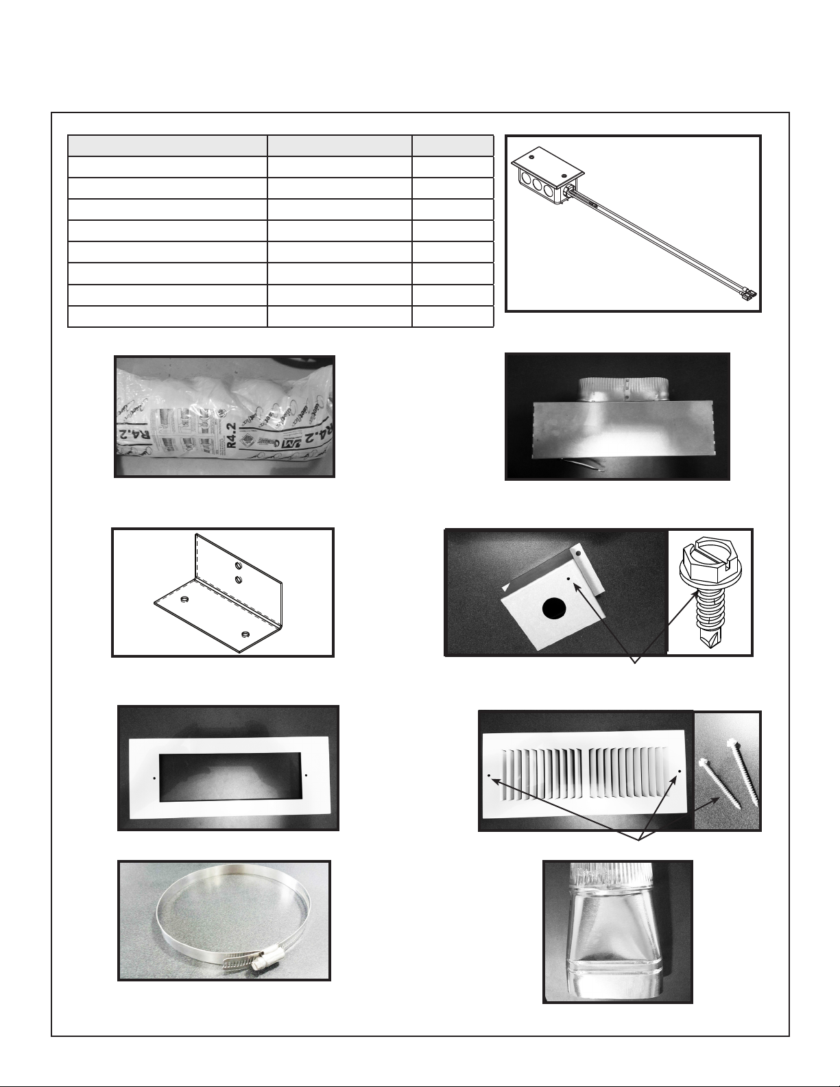
Figure 2. HEAT-ZONE-PRIMO Components
If any parts are missing or damaged, contact your dealer before
starting installation. DO NOT install a damaged kit.
CAUTION! Do not install damaged components.
DESCRIPTION SERVICE PART NO. QTY
6 in. Round Duct 659-200 2
Fan Housing Assembly 659-001A 2
Junction Box 659-122 2
Air Register 659-150 2
Register Adaptor Frame 695-125 2
Duct Adaptor (Round to Oval) 659-129 2
Gear Clamp: Large 662-803 4
Rheostat Assembly, 105 VAC 2326-216 1
Preliminary Preparation
Contents of HEAT-ZONE-PRIMO
659-200 6 INCH ROUND DUCT 659-001A
659-122
659-150
695-125 REGISTER ADAPTER FRAME
659-129 DUCT ADAPTER: ROUND TO OVAL
662-803 GEAR CLAMP: LARGE
SILVER GROUND SCREW
WHITE REGISTER SCREWS
MOUNTING BRACKET
(Not a service Part)
2326-216 RHEOSTAT ASSEMBLY, 105 VAC
4Heat & Glo • HEAT-ZONE-PRIMO Instructions • 2310-936 Rev. J • 9/20
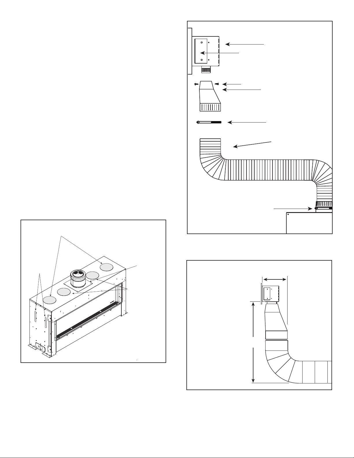
Figure 5.
Figure 4.
• Remove the HEAT-ZONE-PRIMO knockouts on the
top left and right sides of the appliance as shown in
Figure 3.
• Install the HEAT-ZONE-PRIMO collars on the left and
right sides of the appliance with screws. See Figure 3.
• Attach included air duct to the HEAT-ZONE-PRIMO
collars with gear clamps. See Figure 4.
• Attach both mounting brackets to the fan housing.
See Figure 4.
• Mount fan housing in desired location. See Figures 1,
6 and 7.
• Attach round to oval adapter to fan housing with two
screws. See Figure 4.
• Attach included exible ducts to round to oval adapter
with gear clamps.
Note: 6 Inch metal duct can be used in place of the in-
cluded exible ducts.
Figure 3. HEAT-ZONE-PRIMO
18 in.
6-3/4 in.
MINIMUM SPACE
REQUIRED FOR
90 DEGREE BEND
WARNING! Risk of Fire! HEAT-OUT-PRIMO knockouts
MUST remain installed. Appliance could overheat.
WARNING! Risk of Fire! DO NOT fold/kink/pinch/ob-
struct 6 inch exible ducts. Appliance could overheat.
Fan Housing
Round to Oval Adapter
6in. Round Air Duct
Gear Clamp
Screws
Gear Clamp
Mounting Bracket
(Both Sides)
DO NOT
REMOVE
KNOCKOUTS
HEAT ZONE®COLLAR LOCATION
KNOCKOUTS ON TOP
LEFT AND RIGHT SIDES
SQUARE
VENT
PIPE GASKET
HEAT-OUT-PRIMO
KNOCKOUTS

5
Heat & Glo • HEAT-ZONE-PRIMO Instructions • 2310-936 Rev. J • 9/20
Fan Housing Assembly Installation
Note: The fan and electrical connections must be
accessible for servicing per local code requirements.
2 X 6 Wall Mounting
Mount and secure the fan housing assembly to framing
members so the front surface is 1/4 -in. (6 mm) below the
nished wall. Use the adjustable mounting brackets and
screws provided in the kit. See Figure 6 and Figure 7.
Figure 7. Wall Mounting (2 X 4)
Figure 6. Wall Mounting (2 X 6)
Note: The brackets can be rotated 180º and mounted to
the back side of the 2 x 4 if necessary. See Figure 7.
If the fan housing is installed in a 2 x 4 wall, the front of the
housing will protrude approximately 1/2 in. (13 mm) out of
the wall. See Figure 7.
2 X 4 Wall MountingWARNING! Risk of Fire! The PowerFlow™ Heat
Management system must remain ON during operation
of the appliance. Overheating will occur. The appliance
will shut down if the heat management systems are not
operational.
The HEAT-ZONE-PRIMO PowerFlow™ Heat Management
System conveys warm air from the replace through air
ducts to remote locations in the same room or other rooms
in the building. Two Heat-Zones must be installed with
the Primo appliance or the appliance will overheat. Two
HEAT-ZONE-PRIMO’s are included in the kit.
ADJUSTABLE MOUNTING
BRACKETS
FINISHED SURFACE
FRONT OF FAN HOUSING
1/4 IN.
(6 MM)
2 IN. X 6 IN. WALL
FAN HOUSING
14 IN.
4-1/2 IN.
18 IN. MIN.
(457 MM) CLEARANCE TO COMBUSTIBLE ROOM
FURNISHINGS SUCH AS CURTAINS OR FURNITURE
1/2 IN.
(13 MM)
FAN HOUSING
2 IN. X 4 IN. WALL
FINISHED SURFACE
14 IN.
4-1/2 IN.
18 IN. MIN.
(457 MM) CLEARANCE TO COMBUSTIBLE ROOM
FURNISHINGS SUCH AS CURTAINS OR FURNITURE
6Heat & Glo • HEAT-ZONE-PRIMO Instructions • 2310-936 Rev. J • 9/20
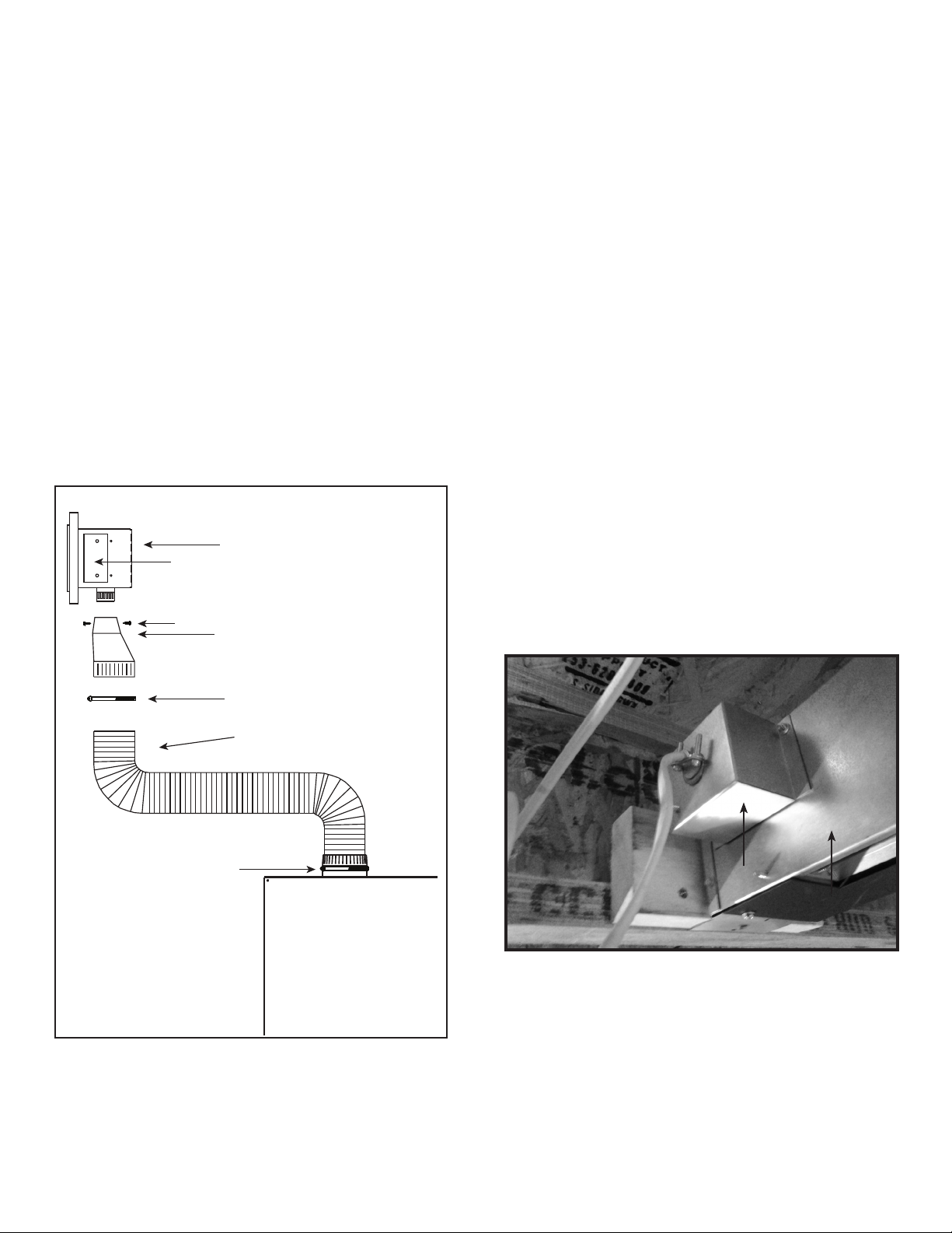
Electrical Connections
Wire 110-120 VAC service from the appliance to the junction
box. See Figure 9. Use wire nuts to secure the 110-120 VAC
service wires to the hot and neutral fan wires and screw the
110-120 VAC ground wire to the fan box. See wiring diagram
in section 8 of the appliance manual.
Place rheostat assembly into appliance to the right of the
valve component tray as shown in Figure 10. Use included
one inch square hook and loop fastener included in kit to
retain the rheostat.
Unplug one of the wires that is currently supplying power to
the thermodisc from the electrical junction box. Plug one
wire from the rheostat assembly into the same location on the
junction box and the other wire from the rheostat assembly
to the wire still attached to the thermodisc. See Figure 12.
Ground the rheostat to the chassis of the appliance with the
included sheet metal screw.
Screw the duct cover to the fan box.
Screw the register adapter frame and the air register to
the fan housing.
Complete the replace installation per instructions.
Other Duct Options
Metal Oval Air Duct: Attach the round-to-oval adapter to
the HEAT-ZONE-PRIMO collar with screws. Attach the 6"
oval duct to the adapter with screws. Complete the duct
run and attach the oval duct to the fan housing. Note: 6
in. metal oval duct is NOT provided with the HEAT-ZONE-
PRIMO kit, but can be purchased from an HVAC supplier.
Metal Round And Oval Duct: A combination of 6 in.
round and 6 in. oval air duct can be used in the duct run.
Metal duct components may be purchased from an HVAC
supplier.
Note: Support duct at intervals of no greater than four
feet, with no more than 1/2 in. sag between supports as
required by local code. Tape all seams with aluminum tape
(1-1/4 in. minimum width, or as specied by local codes).
Figure 8.
CAUTION! Risk of Overheating! Tape seams to prevent
overheating and shut down of appliance.
Figure 9.
Plan the location of the replace and the warm air duct run(s).
JUNCTION BOXJUNCTION BOX
FAN HOUSINGFAN HOUSING
NOTICE: This appliance must be electrically wired
and grounded in accordance with local codes or, in the
absence of local codes, with National Electric Code ANSI/
NFPA 70-latest edition or the Canadian Electric Code
CSA C22.1.
Fan Housing
Round to Oval Adapter
6in. Round Air Duct
Gear Clamp
Screws
Gear Clamp
Mounting Bracket
(Both Sides)

7
Heat & Glo • HEAT-ZONE-PRIMO Instructions • 2310-936 Rev. J • 9/20
Figure 11. HEAT-ZONE-PRIMO Configuration
HEAT-ZONE-PRIMO HEAT-ZONE-PRIMO
HEAT-ZONE-PRIMO Collar HEAT-ZONE-PRIMO Collar
LED Color Switch
HEAT-ZONE-PRIMO Feature - Configuration
WARNING! Risk of Fire! Either the HEAT-ZONE-PRIMO
or the HEAT-OUT-PRIMO PowerFlow™ Heat Manage-
ment system must remain ON during operation of the ap-
pliance. Overheating will occur. Appliance will shut down.
HEAT-ZONE-PRIMO
Maintenance
Service and maintain the gas replace per instructions.
Keep the air register(s) clean and free of any blockage.
Figure 10. Location of Rheostat in Control Cavity
RHEOSTATRHEOSTAT
VALVE COMPONENT TRAYVALVE COMPONENT TRAY

8Heat & Glo • HEAT-ZONE-PRIMO Instructions • 2310-936 Rev. J • 9/20
Please contact your Heat & Glo dealer with any
questions or concerns.
For the location of your nearest Heat & Glo dealer,
please visit www.heatnglo.com.
Heat & Glo, a brand of Hearth & Home Technologies
7571 215th Street West, Lakeville, MN 55044
www.heatnglo.com
Figure 12. HEAT-ZONE-PRIMO Wiring Diagram
RC300 4.5V DC
(AAA X 3)
2273-308
2310-211
6V TRANSFORMER
BLK BLK
2206-299 LOCK OUT
RESET SWITCH
2196-150
PVI MODULE
2196-200 PVI-WIRE HARNESS
HEAT-ZONE-PRIMO
LED’S
2310-062
2155-204
LED SWITCH
2155-752
JUNCTION BOX
2310-211
2166-335 AUX
2155-755
(PRIMO72ST ONLY)
107-558A MALE/FEMALE
WIRE HARNESS
PVI-SLP
2155-033
JUMPER
WIRE
PVLP-SLP
2005-021
WIRE PLUG
ASSEMBLY
2310-202
THERMODISC
2310-204
THERMODISC
PVI-SLP OR PVLP-SLP REQUIRED
2300-753
JUMPER WIRE
PVI-WHXX
Thick line denotes wiring
supplied by electrician.
RED
BROWN
2179-900
2159-310
2273-308
SEE THROUGH ONLY
2310-200
2326-216
RHEOSTAT ASSEMBLY
Other manuals for PRIMO48
1
This manual suits for next models
6
Table of contents
Other HEAT GLO Heater manuals


