Heat Siphon Z Series User manual
i
Copyright 2019 United States ThermoAmp Inc. ALL RIGHTS RESERVED
Publisher: United States ThermoAmp Inc.
1223 Heat Siphon Lane , Latrobe, Pa. 15650
724-537-3500
Owner’s Manual
with Installation & Troubleshooting Instructions
For Heat Siphon® Swimming Pool Heat Pumps
All Z & C Series Heat Siphon Models including
220Volt -1 Ph-60 Hz ONLY: C200HP, C250HP, C375HP, C575HP, Z250HP, Z375HP , Z575HP, Z700HP
220Volt -1 Ph-50 Hz ONLY: C200HP50, C250HP50, C375HP50, C575HP50, Z250HP50, Z375HP50 , Z575HP50
220Volt -3 Ph-50/60 Hz: C250HP3, C375HP3, C575HP3, Z250HP3, Z375HP3 , Z575HP3, Z700HP3
380/460 Volt - 3 Phase - 50/60 Hz - C200HPX, C250HPX, C375HPX, C575HPX, Z250HPX, Z375HPX, Z575HPX, Z700HPX
440 Volt - 3 Phase - 60Hz - C575HP4, Z575HP4, Z575HP4, Z700HP4
200,375,575 Series Heat Only Models 575HC and 700HP Series Models

ii
Thank you for purchasing your Heat Siphon® Swimming Pool Heat Pump.
Since 1983, Heat Siphon® has stood alone as the most innovative, most efficient and most reliable pool or spa
heater made. Over the years our success and innovation has bred a few assemblers and manufacturers who have
made look alike pool heaters and who have adopter many of our features.
But MAKE NO MISTAKE - We have invented, designed and pioneered most of what has become the swimming pool
heat pump of today. Heat Siphon® was the first pool heater to use a titanium heat exchanger, the Copeland Scroll
compressor and vacuum formed PVC cabinets. We are the only pool heater manufacturer using a patent pending
electrically isolated heat exchanger backed by an unconditional lifetime full replacement corrosion warranty. We
have consistently had the highest efficiency ratings in the industry.
Heat Siphon has been made in Latrobe, Pennsylvania since 1983. We are a true MADE IN AMERICA MANUFAC-
TURER. We started here and never left. Today, we believe Manufacturing is coming back to the USA.
We process raw material into finished product to maximize in house manufacturing so we can control the quality
and reliability of our product. We completely fabricate our water side heat exchanger including all brass, teflon,
stainless and titanium fittings and seals inhouse. We vacuum form UV stabilized PVC cabinets from raw material.
We use in-house computer controlled (CNC) equipment including lathe, mill, 5 axis router, tube cutoff and
3 axis tube bender, TIG orbital welding and vacuum forming machines, automated production testing as well as
custom made manufacturing equipment and tooling all to help our production personnel build what we believe
is the best pool heater made.
And if something does go wrong, we spend more per unit than any pool heater manufacturer to ensure your
problems are quickly resolved.
We are constantly looking for ways to improve. You can rest assured that if there is a better way to build it, we
will find it and if there is a better way to serve you we will do it.
And please remember our company motto . . . "WE PERFORM TO KEEP YOU WARM"!!
So, If you have any questions, concerns or suggestions - We would LOVE to hear from you!!
Sincerely,
____________________________________
William P. Bernardi, President, United States ThermoAmp Inc.
Greetings from the President
of United States ThermoAmp Inc.
Weperformtokeepyouwarm
MadeinLatrobePasince1983

iii
Table of Contents
Owners Section ..........................5
1 How Heat Siphon® Works ....................5
2 Heat Siphon® Exterior Parts ...................6
3 Use a Qualified Installer ......................7
4 Plan Your Installation .......................7
4.1 Picking The Proper Size Heat Siphon®...........7
4.2 Locating Your Heat Siphon®.................7
4.3 Provide Full Flow - No Bypass ...............8
4.4 Provide Proper Clearance & Fresh Air ...........8
5 Pool Heating Considerations ...................9
5.1 Sizing Your Heat Siphon....................9
5.2 Pool Pump Run Time.....................10
5.3 Filtration Considerations ..................10
6 Owner Troubleshooting .....................11
6.1 Unit Does Nothing ......................11
6.2 Unit Tries to Start then Does Nothing..........12
6.3 Unit Runs But Doesn’t Heat ................12
6.4 Unit Runs & Heats But Leaks Water...........13
7 Maintenance & Winterizing ..................13
7.1 Lubrication............................13
7.2 Cleaning .............................14
7.3 Winterizing ...........................14
Installer Section.........................16
1 Receiving Shipment........................16
1.1 Moving & Handling Precautions .............17
2 Planning Installation .......................17
2.1 Physical Location .......................18
2.2 Prohibited Locations .....................18
2.3 Distance From The Pool ...................19
2.4 Distance from The Spa....................19
2.5 Pool Piping Required. ....................19
2.6 Electrical Power Required. .................20
3 Wiring Heat Siphon®.......................20
3.1 Electrical Hookup on Unit..................21
3.2 Code Requirements......................21
3.3 Supply Circuit Wire Size ...................21
3.4 GFCI Breaker Protection ...................22
3.5 Electrical Disconnect Switch................23
3.6 Electrical Bonding Requirements.............23
4 Special Installations........................24
4.1 Indoor Pools...........................24
4.2 Multiple Units .........................24
4.3 SPA Heating Issues - See APPENDIX D...........25
4.4 Tools / Materials Required .................26
4.5 Optional Recommended Materials ...........26
4.6 Helpful Hints ..........................26
5 Final Power Line Wiring.....................27
6 Final Plumbing into Pool or Spa ...............27
6.1 In Floor Cleaning Systems..................28
6.2 Pool Spa Combo Plumbing.................28
1 Pump- Heating Pool or Spa.................30
1 Pump- Spillover Mode ....................31
2 Pump- Heating Pool or Spa Only .............32
2 Pump- Spillover Mode ....................33
Initial Start-up..........................34
1 Initial Performance Checks ...................34
1.1 First Startup of Analog Models ..............34
1.2 First Startup of Digital Models ..............35
1.3 Adjusting the Water Pressure Switch ..........35
1.4 Water Pressure Switch Location: .............36
Digital Player Section.....................37
1 Reading The Player Display...................37
1.1 The Player Display Info ...................38
1.2 LED STATUS Lights.......................38
2 Changing Pool Temperature ..................39
2.1 Changing Units (°F / °C) ..................39
3 Player Operating Modes.....................39
3.1 POOL Mode ...........................40
3.2 SPA Mode ............................40
3.3 OFF Mode ............................40
3.4 AUTO-PIC Mode ........................40
3.4.1 How AUTO PIC Works .................40
3.4.2 AUTO PIC LED lights and display ..........40
3.5 EC Mode (External Control) ................42
3.6 TEST Mode............................42
4 Switching Modes .........................42
4.1 Pool/Spa/Auto/Off ......................42
4.2 Entering EC Mode .......................43
4.2.1 Changing MAX EC set point .............43
4.2.2 Manual OFF in EC Mode ...............43
4.2.3 Exiting EC Mode .....................44
4.3 Switching Modes - For Heat/Cool Units Only ....44
4.4 Locking the Player.......................44
5 Special Settings in TEST mode.................44
6 Commercial Player Spa Modes ................45
6.1 STOP SPA Option........................45

iv
HEAT SIPHON® Owner/Service Guide
6.2 T-SPA - Timed SPA Mode ..................45
7 Error and Warning Codes ....................46
7.1 Low Refrigerant Pressure (Lo P) .............47
7.2 Low Air Temp. Warning (Lo A) ..............47
7.3 High Refrigerant Pressure (Hi P) .............48
7.4 Low Water Flow (Lo / FLO).................48
7.5 Water Sensor Open (SH o) .................49
7.6 Water Sensor Short (SH S) .................49
7.7 High Volts (H i / UoLt) ....................49
7.8 Low Volts (Lo / UoLt).....................49
7.9 Main Contactor Short (HS S)................50
7.10 Main Contactor Open Circuit (HS o) ..........50
7.11 Can’t Heat (CAnt / HEAt)..................50
7.12 Air Temp Sensor Open (SA o) ..............50
7.13 Air Temp Sensor Short (SA S)...............50
7.14 No POD (no / Pod) ......................51
7.15 PumpJump Coil Short (PJ S) ...............51
7.16 No Flow w/ Pump Jump(Lo F / Pod) .........51
7.17 Flow w/ Pump Jump (FLO / Pod) ............51
7.18 Pod Coil Open (no / Pod) .................51
7.19 High Air Temperature (Air / Hi) .............52
7.20 Low Air Temperature (COLD / xxF) ..........52
7.21 Reversing Valve Coil Open (CH o) ...........52
7.22 Reversing Valve Coil Short (CH S) ...........52
7.23 Easy Pic/Clock No Board (no / EASy) .........52
7.24 Circuit Board Errors .....................52
Analog TimerStat Pro Section ..............53
1.1 Still Keeping it Simple ....................53
1.2 Easy to Upgrade to Digital .................53
1.3 Timerstat Pro Error Codes - Status LED .........53
Appendix A .......................... A-55
Analog Model Wiring Diagrams ...............A-55
TimerStat Pro 220 volt-1 ph-50/60Hz (2 Pole) ...A-55
TimerStat Pro 220 volt-1 ph-50/60Hz (3 Pole) ...A-56
TimerStat Pro 220 volt-3 ph-60Hz ...........A-57
TimerStat Pro 380 volt-3 ph-50Hz ...........A-58
TimerStat Pro 440 volt-3 ph-60Hz ...........A-59
Digital Model Wiring Diagrams................A-60
Digital 220 volt-1 ph-50/60Hz (2 Pole) ........A-60
Digital 220 volt-1 ph-50/60Hz-(3 Pole)........A-61
Digital 220 volt-3 ph-60Hz ................A-62
Digital 380 volt-3 ph-50Hz ................A-63
Digital 440 volt-3 ph-60Hz ................A-64
Appendix B ...........................B-65
Specifications by Model .....................B-65
Classic "C" Series (TimerStat Pro Equipped) .....B-65
Digital "Z" Series (Player Equipped)...........B-65
Classic "CF" Flow Sensing Series .............B-66
Digital "ZF" Flow Sensing Series .............B-67
Appendix C ...........................C-68
Accessories Available....................... C- 68
1.1 Hardwired Add-Ons ................... C- 68
1.2 Wireless Add-Ons..................... C- 69
1.3 Other Accessories ..................... C- 69
Appendix D .......................... D-70
SPA / HOT TUB Heating Issues .................D-70
WARNING! Water Temperature Safety ...........D-70
Thermostat Set Point Depression . . . . . . . . . . . . . . . D-71
Spa Temperature Sensor Calibration.............D-73
Spa Thermostat Set Points above 102°F ..........D-74
USA Warranty Certicate ..................76
HEAT SIPHON® Owner Section
Owner - 5
Owners Section
The Owner Section is written specifically for you, the pool owner. It explains proper operation and maintenance
of your Heat Siphon.
Heat Siphon® Overview
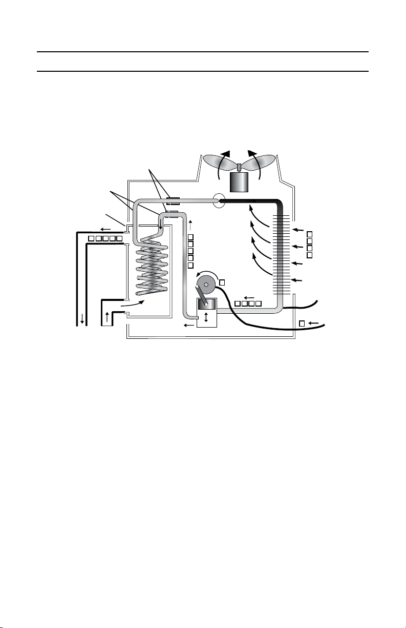
1 How Heat Siphon® Works
Heat Siphon® is a heat pump designed specifically for recreational water heating (pools and spas).
If you have an air conditioner, dehumidifier, water cooler or a refrigerator, you already own a heat pump. All
these appliances use the same dependable technology to move heat from one place to another using electric power
and a sealed refrigerant compression system. Just like a room air conditioner moves 2 to 3 units of heat from your
home for every unit of electricity it consumes, Heat Siphon® uses 1 unit of electric energy to move 4 units of heat
from the air and thus it provides 5 units of heat to your pool.
Referring to the diagram above - A unit of electrical energy (you pay for) goes into the compressor motor (1) .
The compressor turns this into mechanical energy and sucks cool gas from a gas-liquid refrigerant mixture in the
evaporator tubes. As the refrigerant evaporates it absorbs four units of "free" heat from the warmer air that the fan
pulls over the outside of the evaporator tubes.
The compressor squeezes this gas causing its temperature to climb above 200° F and adds the electrical/me-
chanical energy as another unit of heat. This hot high pressure gas then enters the condenser coil (2) and heats
the colder (80° F) pool water being circulated over the outside of the coils.
As it cools, the refrigerant gas condenses back to a liquid at high pressure then rapidly expands thru a valve (3)
back to the lower evaporating pressure.
This rapid pressure drop super cools the liquid refrigerant as it enters the evaporator (4) where it repeats the
Evaporator
Fan
Expansion
Valve
Compressor
Heat Siphon
Condenser
1
2
3
4
Electricity
Pool Water
Electrically Isolated
Titanium Fittings
Pure
Titanium Tubing
(Freon Inside)
PVC Shell
ELECTRICAL
GROUND

HEAT SIPHON® Owner Section
Owner - 6
cycle. SO YOU PAY FOR ONE UNIT OF HEAT AND GET FOUR FREE!! . . . And with the NEW models you get FIVE
to SIX units FREE!!
2 Heat Siphon® Exterior Parts
The following Illustration identifies the basic exterior components and parts of your Heat Siphon.
Heat Siphon® Exterior Parts
FAN GUARD
STAINLESS STEEL
FASTENERS
WARM AIR
IN
EVAPORATOR
VENTURI TOP
JUNCTION BOX
Power In (Wire Nuts)
ELECTRICAL
CONDUIT ¾” NPT
COOL AIR
OUT
WATER OUTLET to Pool
1½” SCH 40 Slip Inside and
2” SCH 40 MPT Outside
DIGITAL MODELS
Player Controller
ANALOG MODELS
TimerStat Knob
ELECTRICAL
CONTROL BOX
HAND HOLE
GRIPS
BONDING LUG
NAMEPLATE
BACK PANEL
BASE PAN
CONDENSATION DRAIN
Barb Fitting for ¾”Vinyl Tubing
SVC PORT DOOR
Hi/Lo Pressure Refrigerant
Std. ¼” MFL Fittings
WATER INLET from Pump
1½” SCH 40 Slip Inside and
2” SCH 40 MPT Outside
Don’t Void Your Warranty!
This section contains all the information you will need to ensure that your Heat Siphon® has been properly
installed. Read this section before allowing a new dealer to install your unit. If your installer is not an Authorized
Heat Siphon® Dealer make sure they are licensed by your county, trained and have experience installing pool
plumbing, wiring and pool heating equipment.

HEAT SIPHON® Owner Section
Owner - 7
3 Use a Qualied Installer
Although your Heat Siphon® Swimming Pool Heat Pump has the strongest manufacturer’s warranty of any
pool heater made, there are things your installer could do incorrectly to cause you problems and expenses which
will not be covered by the factory under this warranty. (See the Appendix for your Heat Siphon® Factory Warranty.)
As the owner you should be aware that your Heat Siphon installer is totally responsible for performing the following
key installation steps.
4 Plan Your Installation
You and your Dealer / Installer must be responsible for the following
• Picking the Proper Size Heat Siphon® for Your Pool
• Selecting the Proper Location
• Providing Proper Air / Service Clearance Around the Unit
• Correctly Plumbing for FULL PUMP FLOW - NO BYPASS
NOTE: FAILURE TO DO SO MAY VOID YOUR WARRANTY!!
4.1 Picking The Proper Size Heat Siphon®
Your dealer should provide you with a Heat Siphon® that is large enough to heat your pool under normal
conditions within 8-12 hours of run time each day. Under-sizing will result in long run times and possibly a pool
which isn’t always as warm as you want it to be.
Normally a Z375HP Heat Siphon® will be more than adequate to heat most in ground residential pools to
over 82° F. Most established Heat Siphon® dealers, can tell from experience what size will work on your pool. If
there is a doubt about sizing, or if you have a larger pool , abnormal wind or shade or you wish to keep your pool
uncovered 24 hours a day, then make sure your dealer has taken this into account.
TIP: Anyone can request our free factory computer pool heating analysis. It very accurately determines the
proper size (and number) of Heat Siphon(s) for your pool as well as the expected heating cost. You specify your
location (for climate data), the pool temperature you desire, the months it will be open, the hours per day covered,
the wind condition, the pool pump hours and your local fuel costs. It will be emailed or FAXED back SAME DAY.
This four page printout also provides graphics showing pay back period, monthly operating cost and much
more and it’s FREE. (See the sampleon our website www.HEATSIPHON.com)
4.2 Locating Your Heat Siphon®
As long as you provide plenty of fresh air and give it adequate clearance space all around, Heat Siphon can be
installed virtually anywhere outdoors. Unlike gas heaters whose pilot lights can be blown out, Wind has no effect on
Heat Siphon® other than possibly helping the fan and increasing the heat output. Do not place your Heat Siphon®
under a deck, in a pump house or under a roof overhang. These locations do not provide "fresh air", instead they
cause air recirculation, reduce efficiency and compressor life and void your warranty.
It’s solid PVC cabinet , stainless steel hardware , vinyl coated fan guard and evaporator screen will remain un-
affected by the elements. The plastic basepan has a drain fitting to carry rain water as well as condensation away

HEAT SIPHON® Owner Section
Owner - 8
from the unit. A 3/4” diameter clear vinyl tube will slip right over this barb type fitting to plumb the water away.
As far as direct sunlight is concerned, Heat Siphon’s UV stabilized, flame retardant PVC plastic cabinet material
is far superior to any type of galvanized or painted sheet metal cabinet. It won’t rust, fade, chip or peel.
If the air temperature drops below about 42°F while the Heat Siphon® is running then any water in the air
will begin to freeze and form frost or ice on Heat Siphon’s large horseshoe shaped evaporator fins. This is because
Heat Siphon®’s refrigerant must be colder than the air to remove heat from it and dips below freezing at about
this air temperature.
Although this will cause no structural damage, it may take as much as 24 hours to melt and it will drastically
reduce efficiency. Over a long period this can reduce the life of your compressor.
To prevent this icing your Heat Siphon® is equipped with a freeze protection switch that automatically turns
the Heat Siphon® off if the refrigerant temperatures goes below freezing. It will automatically restart and continue
heating the pool as soon as there is no icing danger at about 48°F.
4.3 Provide Full Flow - No Bypass
WARNING
Any damage due to incorrectly plumbing your Heat Siphon installation is
not covered by the warranty.
DO NOT INSTALL A BYPASS
Heat Siphon® requires FULL PUMP FLOW with at least 25 to 30 GPM.
Heat Siphon®’s full flow heat exchanger will accept up to 80 GPM with
very minimal pressure drop. Installing a bypass can reduce flow below the
minimum required and overheat the condenser causing the unit to cycle
on and off every 5 minutes. If allowed to continue, cycling can shorten the
unit’s life and damage the compressor which is not covered by the warranty.
DO NOT INSTALL SHUTOFF VALVES DOWNSTREAM
Plumbing shut off valves downstream of the Heat Siphon® in a way that
results in the pool pump pressurizing the Heat Siphon® with no water flow
can also cause short cycling damage.
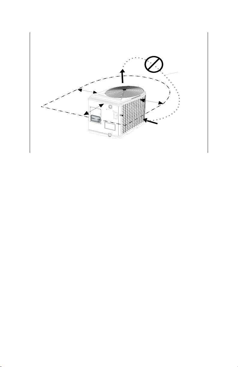
4.4 Provide Proper Clearance & Fresh Air
Heat Siphon® can not be installed where the cooler exhaust air (flowing straight up out of the unit) is recirculated
back into the intake (sides) of the unit. This will reduce efficiency as well as heat output.
HEAT SIPHON® Owner Section
Owner - 9
HEAT
SIPHON
Heat Siphon Installation Space Required
for Air Flow & Service Access ALLOW 12 to 24 inches AROUND ALL SIDES
12”Min 12”Min
24-36" Service Access
Colder Air Out Top
Warmer Air In Sides
PREVENT
Air
Recirculation
At least two feet of clearance must be provided around the unit as well as unrestricted air flow overhead.
Installing a Heat Siphon® under a deck or in a pool equipment shed or enclosed area or too close to shrubs
will result in air recirculation, poor performance and short cycling which can shorten the unit’s life and damage
the compressor AND WILL VOID THE WARRANTY.
5 Pool Heating Considerations
5.1 Sizing Your Heat Siphon
Heat Siphon® is equipped with a flow sensing switch which turns it on and off automatically when the pool
pump is turned on or off. However, you must still run the pool pump long enough each day to allow Heat Siphon®
to maintain the pool water temperature.
Make sure that your dealer provides you with a Heat Siphon® that is large
enough to heat your pool under normal conditions with 8-12 hours of
pump operation each day
If the pool pump is off during the night and the pool loses heat then it may take several hours or more in the
morning to restore the pool to temperature. If your pool pump is sized to run 8 hours per day for filtration, during
a cold spell or other high heat loss period such as when the pool is uncovered for an extended windy period, the
Heat Siphon® may require longer pump operation to maintain temperature. This will not require excessive pool
pump operation and will ensure a reserve heat output capacity to cover any temporary high heat loss conditions.
A properly sized Heat Siphon® and a smaller pool pump are the most cost effective combination to ensure proper
pool heating and filtration. If in doubt call the factory and we will be glad to furnish a free computerized pool
or spa heat loss analysis that will show recommended pump operating times and operating costs for each month

HEAT SIPHON® Owner Section
Owner - 10
Including extra pool pump electric costs if you do choose to oversize.
Tip: Visit our website WWW.HEATSIPHON.COM for a sample print out or DOWNLOAD our iPhone/iPad Pool
Designer app MYPOOL at the App Store.
5.2 Pool Pump Run Time
Just like other pool heaters, Heat Siphon® can add heat to the pool only when the filter pump is running. So
the question is how many hours a day do you run your pool pump- 24, 16, 12 or 8 hours per day?
NOTE: In ANY given pool or spa piping system, if you DOUBLE the flow
rate, you QUADRUPLE the WATTS needed to pump water thru it. Put
another way - PUMPING 1000 GALLONS IN ONE HOUR through your
pool filter TAKES 4 TIME THE WATTS as pumping 1000 GALLONS IN
TWO HOURS!!
How long to run your pool pump each day?
1. You must run the pool pump long enough to FILTER OUT ANY DIRT AND DEBRIS.
2. You must run the pool pump long enough to allow the HEATER to REPLACE THE DAILY HEAT LOSS.
3. If you use a feeder, chlorinator, ionizer etc., the manufacturer’s recommendations must be followed.
Picking a pump too small OR running a variable speed pump on low speed will result in inadequate filtration
time. Using a pump that is too large OR running a variable speed pump on high speed will increase both system
back pressure and electric cost.
The most efficient and lowest cost pool pump system is one where the pool pump has a flow rate just large
enough to pump (turn over) your entire pool volume through your filter in 8 to 12 hours. This means running the
pump continuously to get the recommended 2 to 3 turnovers per day for proper filtration while pumping against
the lowest back pressure possible.
5.3 Filtration Considerations
The number of bathers, amount of chemicals added as well as the temperature and weather all vary the actual
filtration required to maintain a clear clean pool.
In most commercial pools, state laws usually require 3 turnovers per day with the pump running 24 hours per
day (one turnover every 8 hours). Thus a 80,000 gallon pool would need a pump flow rate of 10,000 gallons per
hour or 167 gallons per minute (GPM) to pump the entire volume through the filter in 8 hours. 60 GPM equals
1 Gallon per Hour (GPH).
Pool Turnover Time in Hours = Pool Gallons/ Pump GPH
On residential pools 1.5 to 2 turnovers per day is usually considered the minimum. The size (horsepower) of
your pool pump will determine the flow rate in your pool filter system and thus how many turnovers per day can
be achieved.
Bigger pumps are not necessarily better. Some dealers put in a smaller pool pump sized to run 24 hours a day
because the operating cost is much less per day than running a larger pump for 8-10 hours to get the same number

HEAT SIPHON® Owner Section
Owner - 11
of turnovers. Back pressure increases as the square of the flow rate. Thus, if you cut the flow rate in half in a given
pool piping system, you decrease the back pressure that must be overcome to pump the pool water by 75%. In addition
they claim 24 hour run time saves chemical costs by eliminating shock treatments and by keeping turbidity and
suspended solids to an absolute minimum.
On the other hand are dealers who advocate using large 1. 5 or 2 horsepower filter pumps which turn over
the entire pool volume in 4 to 6 hours and thus they claim need only be run 8-12 hours daily to achieve effective
filtration. If you have different electric rates for day versus night usage, running your pool pump for a shorter time
during “off peak” rates may actually save pump costs overall even though you use more electricity. Ask your dealer
if in doubt or call your electric utility.
The pump flow rate requirements are also affected by the size and type of filter you use. Cartridge filters usually
require 1 GPM (gallons per minute) per square foot while diatomaceous earth may require 2 GPM per square foot
and sand 3 GPM / sq ft. or more. Thus a lower flow rate pump which runs longer can use a smaller but not under-
sized filter as long as it will not load up too quickly. If a large filter is used with the smaller pump, back pressure
will also be reduced significantly thus further reducing pump electric costs.
In conclusion, in most cases using a longer run time with a smaller pump and a properly sized or even oversized
filter clearly provides the best results from an economic as well as a filtration standpoint.
6 Owner Troubleshooting
The purpose of this section of the manual is to provide some GUIDANCE FOR HEAT SIPHON® OWNERS with
little or no technical background who have a problem with their Heat Siphon®.
If our guidance here doesn’t solve the problem CALL YOUR INSTALLER and refer him to the Installer Section of
this manual. He will contact the factory service center for additional service if required.
When you apply power to your Heat Siphon® through the disconnect and circuit breaker, usually one of four
things will happen
• IT DOES NOTHING
• IT TRIES TO START THEN SHUTS OFF
• IT STARTS & RUNS but doesn’t heat
• IT RUNS & HEATS & sometimes leaks water
In any case you are probably reading this because your pool is not
heating to the desired temperature, so follow the appropriate steps
below BEFORE CALLING YOUR DEALER:
6.1 Unit Does Nothing
Here is a step by step troubleshooting procedure if your
unit does not start
1. Is power on?
2. Thermostat set too low? ( turn fully clockwise-unit should come on)
3. Pool pump on and valves properly set?
4. Water flow confirmed from pool through heater and back to pool?
42°F
Heat Siphon Shuts Down Below 42°F
to Prevent Evaporator Icing and
Automatically Restarts at 48°F

HEAT SIPHON® Owner Section
Owner - 12
5. Air too cold? - Air temperature below approx. 42°F will shut unit off automatically to prevent icing. (Wait for
air temperature to reach 45° F to 48° F - unit should automatically reset and turn itself on)
6. Time delay activated by brief power interruption? (Wait 5 minutes - unit should restart)
7. Is breaker tripped? You may have a bad breaker or faulty wiring, loose wires or poor connection in the junction
box . Have your installer check the wiring and breaker.
NOTE: Some brands of GFI type breakers are extremely sensitive and
are susceptible to false tripping. Have your installer check all wiring
between the unit and the breaker and make sure the breaker is wired
right . (see installer section)
8. Call your dealer. - His first step should be to check & adjust the water flow switch
6.2 Unit Tries to Start then Does Nothing
1. Has the Time delay been activated by brief power on/off? (Wait 5 minutes - unit should restart)
NOTE. The combination of a cold pool (below about 50°F) and a low air temperature (below
about 45°F) MAY cause temporary on off cycling of the Heat Siphon. A pool cover and /or 50°F air
temperature will eliminate this cycling and allow normal heating operation to resume.
2. Is the air below 45°F to 48°F and the pool water cold? (Wait for air temperature and/or pool to reach 50°F
- unit should restart automatically and resume normal heating)
3. Is the pool filter clean and pool water flow stable? A clogged filter or air leak in the pool pump return line
can cause erratic water flow and air in the lines which in turn can cause Heat Siphon® to cycle- restore
the correct water flow.
4. Is the fan running when the unit is running? - (if not call dealer)
6.3 Unit Runs But Doesn’t Heat
Check these before calling your dealer:
1. Air leaving colder? If not call dealer
NOTE: If Heat Siphon®’s air outlet is noticeably (5 to 10°F) cooler than the inlet air, then the
unit is providing heat to pool. The unit may not have been running long enough to heat the pool
(see next step), or the unit may be undersized. (See proper sizing section above)
2. Pool pump running long enough each day? Normally 12-14 hours/day is sufficient if Heat Siphon ® is
sized properly (let pool pump run continuously for 24 hours to find time required-if not heating call dealer)
3. Is there abnormally high heat loss? No cover on extremely windy day? (Cover pool and run pool pump 24
hours. If still not heating call dealer)
6.4 Unit Runs & Heats But Leaks Water
Water leaking from INSIDE your Heat Siphon is due to one of two conditions
• NORMAL CONDENSATION as it cools off warm humid air

HEAT SIPHON® Owner Section
Owner - 13
• WATER LEAK in the Heat Exchanger Housing or Internal Hose or Piping.
The most common cause of a water leak is CONDENSATION. The second is a CRACKED HEAT EXCHANGER
CAP DUE TO FREEZING. If you have not properly winterized (See next section) this will not be covered under your
warranty. Before calling your dealer, here are some tests you should perform:
1. TURN OFF YOUR HEAT SIPHON, KEEP YOUR POOL PUMP ON and wait until basepan empties. If the Water
Leak Stops IT IS NORMAL CONDENSATION
2. If the Basepan does not empty BUT THE leaking stops it's still condensation but your drain is blocked so
unclog the barb drain fitting and/or replace the vinyl drain tubing.
3. TEST THE LEAKING WATER for Chlorine - If it tests NEGATIVE it's Condensation.
4. If the water has chlorine and the leak continues, call your dealer
7 Maintenance & Winterizing
As well as being virtually corrosion-free, your Heat Siphon® has been designed and built using strictly high
quality, proven reliable components. As a result, you can expect your Heat Siphon® to outlive other heaters and
to require only minimal maintenance over its lifetime. No regular scheduled maintenance is required and only
minimal cleaning and minor lubrication as noted below
7.1 Lubrication
Your Heat Siphon® has only two rotating parts subject to wear and thus requiring lubrication: the compressor
and the fan motor.
Since the refrigeration system compressor is hermetically sealed which eliminates all air and water vapor
contamination, it requires no lubrication or maintenance. The refrigerant inside is extremely stable, has a special
lubricating oil added which lubricates the compressor bearing. The oil and refrigerant are so stable that under
normal conditions they will easily last more than 30 years without breaking down.
The fan motor which is totally enclosed type motor (sealed from rain and dirt) is equipped with a rain slinger
on its shaft to prevent rain water from washing the lubrication out of its sleeve bearings. This should also require
no lubrication for years, however, after several years of service in a hotter climate or if the motor has set idle in a
hot dry environment for many months, the lubrication may begin to dry out and may cause the fan motor bearing
to make noise. If left uncorrected this will eventually slow down and freeze up the fan motor causing short cycling
and may burn it out.
WARNING: Before removing the fan guard , TURN OFF ALL POWER
TO THE UNIT. ACCIDENTAL STARTING OF THE FAN MOTOR WHILE THE
GUARD IS OFF CAN RESULT IN SEVERE INJURY.
You can re-lubricate the bearings using the oil fittings on the side of the fan motor. Remove the two plastic seal
plugs (one at the top and bottom of the motor housing) and squirt in light machine oil.

HEAT SIPHON® Owner Section
Owner - 14
7.2 Cleaning
WARNING: Before cleaning TURN OFF ALL POWER TO THE UNIT. Al-
though each unit is production tested for any ground faults and the
electrical supply hookup is in a gasketed rain tight housing, a faulty
eld electrical hookup or hidden damage to the unit CAN PRODUCE
A FATAL SHOCK HAZARD. Don’t take a chance- DISCONNECT AND
LOCKOUT THE BREAKER BEFORE CLEANING
CAUTION - DO NOT SPRAY WATER DIRECTLY INTO THE HEAT SIPHON
WITH A HOSE OR OTHER HIGH PRESSURE WATER. Although the Heat
Siphon® Is Rain tight it is NOT WATERPROOF and high pressure water
can be directed in a manner that could cause shorting and even
ELECTRIC SHOCK HAZARD.
Heat Siphon’s solid PVC cabinet may be cleaned using any of the automotive vinyl cleaners, or soap and water.
An abrasive cleaner or bathtub porcelain cleanser will remove most stubborn stains. Dirt and leaves should be swept
from the finned horse shoe shaped evaporator if build up occurs. Spraying water is not necessary to clean Heat
Siphon® and normal dirt accumulation will not have any effect on the unit’s performance.
7.3 Winterizing
Warning: If pool or spa water is allowed to freeze in the heat ex-
changer, it will expand and may crack the heat exchanger housing
requiring heat exchanger replacement which is not covered by the
warranty.
Your Heat Siphon can stand the coldest of winter weather with no problems. The only precaution necessary is to
make sure that the heat exchanger is drained of all pool water. If in doubt add antifreeze to the outlet (top) until
it comes out of the inlet (bottom) of the unit.
In freezing weather the plastic cabinet material does become brittle and should be protected from any impact
but can withstand normal moving and handling.
NOTE: It is totally unnecessary that your Heat Siphon be moved from its
installed location for the winter, and in fact it is recommended that you
leave it intact to avoid damage during moving.

HEAT SIPHON® Installer Section
Installer - 15
Installer Section
This Section of the manual applies to the installer.
1 Receiving Shipment
NOTICE: ALL Shipments by the factory are made F.O.B.. Latrobe, PA. As
such, the buyer (dealer) takes possession of the Heat Siphon® the minute
it leaves the factory loading dock.
United States ThermoAmp, Inc. is NOT responsible for any shipping
damage occurring in transit. THE FREIGHT HAULER IS RESPONSI-
BLE FOR ALL FREIGHT DAMAGE AND ALL DAMAGE CLAIMS MUST
BE SETTLED DIRECTLY WITH THE FREIGHT HAULER. The factory will
assist you in settling claims wherever possible but YOU MUST DEAL
DIRECTLY WITH THE SHIPPER TO RESOLVE ALL FREIGHT DAMAGE.
IMPORTANT.- IF YOU RECEIVE A DAMAGED HEAT SIPHON® NOTIFY
THE CARRIER IMMEDIATELY (THAT MEANS THE CARRIER’S OFFICE,
NOT THE DRIVER)
CAUTION: A unit which has been dropped will have internal damage
which is not apparent from the outside of the carton. If in doubt
unpack the unit in presence of the shipper at the time of delivery.
Puncture marks and oil stains on the box are indicative of a ruptured
and leaking sealed refrigeration system. AND SHIPMENT SHOULD BE
REFUSED.
Heat Siphon® is designed and packaged to ensure safe arrival even with individual shipments, however, if Heat
Siphon® is tailgated or dropped, the damage may not be visible from outside the box and if you accept shipment
from the trucking company, any subsequent claims of concealed damage will be refused by the freight hauler.
Although unattractive, minor dents in the aluminum evaporator fins won’t adversely affect Heat Siphon®
performance, we suggest that you make note of ANY damages on the Bill of Lading BEFORE signing for receipt.
Damaged fins can be “combed” straight, if not severely smashed, with a “fin comb” commonly carried by most
refrigeration repairmen. Black acrylic enamel spray paint can also be used to repair any cosmetic damage.
1.1 Moving & Handling Precautions
If only a few simple handling rules are followed, Heat Siphon® can be moved virtually anywhere with no problems:
1. DO NOT DROP OR TAILGATE THE HEAT SIPHON .
2. DO NOT LAY THE UNIT ON ITS SIDE OR UPSIDE DOWN.

HEAT SIPHON® Installer Section
Installer - 16
3. DO NO LIFT THE HEAT SIPHON® BY ITS TOP / VENTURI - USE HAND HOLES IN BASE.
Use a fork truck, roller conveyor or an inclined plane to unload the Heat Siphon® carton. Although the special
PVC plastic used in the HEAT SIPHON® cabinet is extremely tough and more than adequate for shipment even in
cold weather, it will probably break or crack if dropped from a truck tailgate.
Usually damage will be in one of three places:
1. Where the 25 pound control panel attaches to the base pan;
2. Where the 20 pound fan motor attaches to the top;
3. Where the 75 to 120 pound compressor fastens to the base pan.
Cracked plastic cabinet parts may or may not need to be replaced but can be expensive to replace if all the
components need to be removed and remounted on a new cabinet part.
Other freight damage - bending of the fan motor mounting bracket that causes the fan blade to rub or rupturing
of a copper refrigerant tube. Usually this can be repaired by a local refrigeration service center with minimal difficulty.
If tilted too far from the vertical position, the weight of the compressor can bend or break tubing or even break
or crack the plastic base pan at the compressor mount.
The top venturi/fan assembly is fastened to the unit using three stainless steel screws which are anchored to sheet
metal flanges. This is more than adequate for ensuring a firm vibration-free assembly to the Heat Siphon® body,
but these mounting screws are not designed to support the entire weight of the unit. Once out of the box, the Heat
Siphon® should be lifted by the base pan only. Hand holes have been molded into the basepan for easier handling.
2 Planning Installation
IMPORTANT - READ THIS ENTIRE SECTION COMPLETELY THRU BEFORE
YOU BEGIN TO INSTALL HEAT SIPHON®
The efficiency of your Heat Siphon® is dependent on its location. Picking the wrong place will not only reduce
the efficiency by causing the cooler air coming out of the top to recirculate back into the air inlet, it may void your
warranty. Please read through this section before you decide where to place your Heat Siphon®
HEAT SIPHON® Installer Section
Installer - 17
2.1 Physical Location
HEAT
SIPHON
Heat Siphon Installation Space Required
for Air Flow & Service Access ALLOW 12 to 24 inches AROUND ALL SIDES
12”Min 12”Min
24-36" Service Access
Colder Air Out Top
Warmer Air In Sides
PREVENT
Air
Recirculation
Normally, the pool piping layout and the electrical supply will dictate the general location of the Heat Siphon®.
In addition, the following guideline should be adhered to when picking the location:
1. Allow 24 to 36 inches of open area all around the Heat Siphon® for good air circulation and service access.
Avoid any overhangs or structures which could cause exhaust air to recirculate from the top of the unit back
into the sides.
2. Ensure the Heat Siphon® will be level when in place to aid in condensation and rain water drainage. Sand
or a cement slab will provide and inexpensive attractive easy to level mounting base with good drainage.
3. Heat Siphon’s noise dampened plastic base pan ensures extremely quiet operation. To further minimize
noise, point the flat side of the unit with Heat Siphon® trademark toward areas people will frequent. The
plastic front panel reduces the already low operating sound level even further in that direction by absorbing
compressor noise which the evaporator side does less effectively.
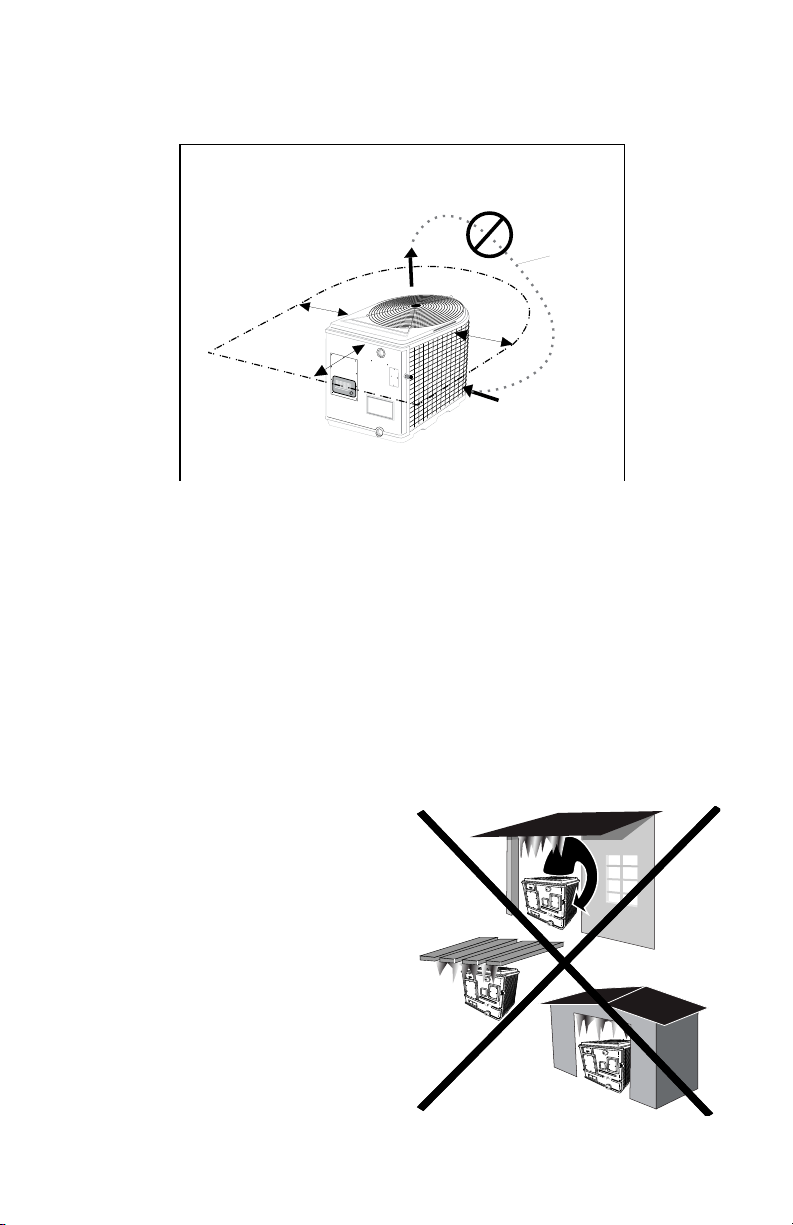
2.2 Prohibited Locations
DO NOT locate your Heat Siphon in any of the following
places, as the air will be recirculated back to the inlet
and cooled down cycling repeatedly until the efficiency is
degraded and the compressor is overworked. Location in
any of these places will void your warranty:
1. Under a roof overhang
2. Under a deck
3. In a Pool Pump house
2.3 Distance From The Pool
Normally, the pool pump and Heat Siphon® are in-
stalled close together and within 25 feet of the pool. The
HEAT SIPHON® Installer Section
Installer - 18
longer the distance from the pool, the more heat loss from the piping. Since most of the time the piping is buried,
the heat loss is minimal for runs of up to 50 feet (50 feet to and from the pump = 100 feet total) unless the ground
is wet or the water table is high. A very rough estimate of heat loss per 100 feet of piping is 2500 BTU/Hr. for every
10°F difference in temperature between the pool water and the ground surrounding the pipe, which translates to
about a 3% to 5% increase in run time.
2.4 Distance from The Spa
CAUTION: Special consideration required using any heater with a spa or
hot tub. SEE APPENDIX D
2.5 Pool Piping Required.
IMPORTANT: Allow At Least 12 Inches Of Straight Pipe Between The
Heat Exchanger And Any Coupling Unions Or Elbows To Allow Backpanel
Removal For Servicing .
CAUTION: DO NOT USE ANY BYPASS PIPING. Heat Siphon® Requires
Full Flow From 25 T0 80 GPM. Installing A Bypass May Cause Short Cy-
cling Damage and Will Void Your Warranty.
The Dual-Fitting water ports allow you to glue either 1.5 inch or 2 inch (with a standard 2” PVC coupling)
schedule 40 PVC pipe directly into the heat exchanger. No metal heat sink piping is required. The following graphic
applies to all C & Z 200, 250,375 & 575 series heating only and cooling only models:
Heat Siphon’s exclusive FULL FLOW Titanium heat exchanger has a minimal pressure drop and requires NO
SPECIAL PLUMBING arrangement. It should be considered as just another length of PVC pipe in your pool filtration
system.
Heat Siphon® Plumbing Installation
Plumb Schedule 40 PVC Pipe 1½”or 2” Diameter Directly into and out of Unit
FULL FLOW - NO BYPASS!!
Pipe Couplers
for Winterization
& Service Bypass
Condensate Drain
in Basepan Hand Hole
Barb Fitting accepts
¾” Vinyl Tubing
FROM PUMP
TO POOL
MINIMUM of 12” of Straight Pipe
between unit to couplers
for panel removal / service
For C & Z Series
200HP / 250HP,
375HP / 575HP Models

HEAT SIPHON® Installer Section
Installer - 19
LOCATION: Connect Heat Siphon® in the pool pump discharge (return) line DOWNSTREAM of all lters and pool pumps,
and UPSTREAM of any electronic chlorinators or chemical pumps.
SIZE: All Heat Siphon®’s have 1.5 “ x 2” ttings for connection to the pool or spa ltration piping which will accept 1.5”
schedule 40 PVC pipe directly or 2” SCH 40 PVC pipe with a 2” PVC coupling. The in-line water pressure drop produced
by Heat Siphon is less than 1.5 psi at 30 GPM.
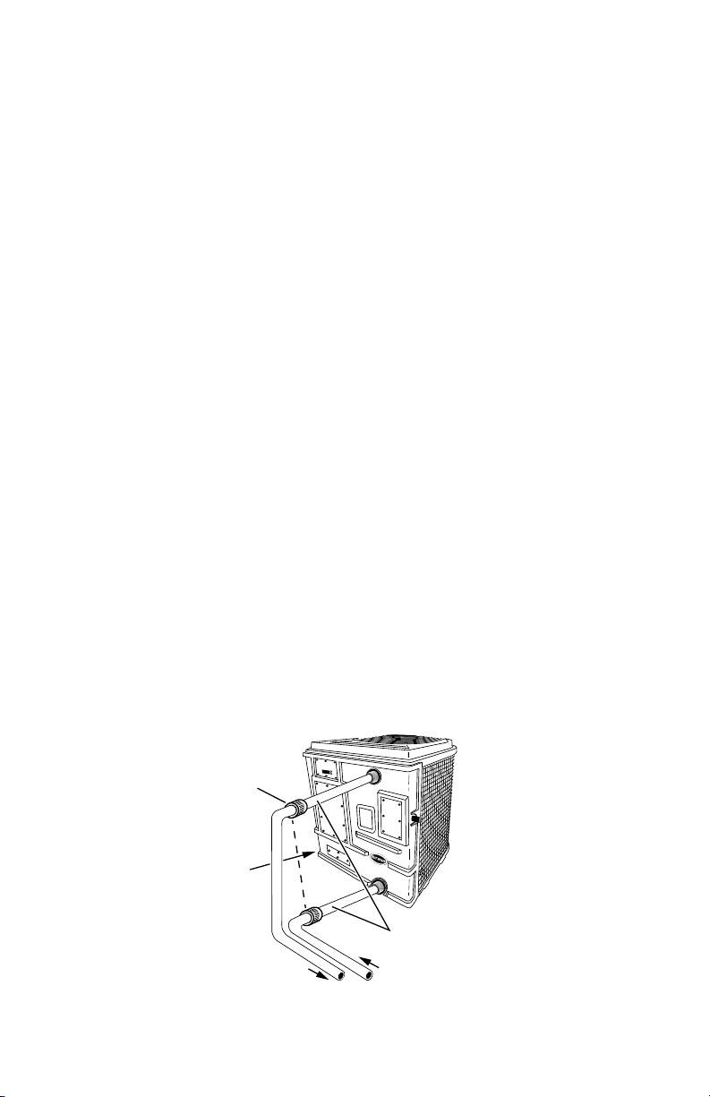
The following graphic applies to all 575 series Heat/Cool models and all 700 series Models
2.6 Electrical Power Required.
WARNING: DO NOT ATTEMPT TO COMPLETE ANY ELECTRICAL IN-
STALLATION OR SUPPLY CIRCUIT WIRING UNLESS YOU ARE QUALI-
FIED AND EXPERIENCED IN THE FIELD. Heat Siphon® Requires High
Voltage Power Wiring Which Should Be Installed In Accordance With
All Electrical Codes By A Licensed Electrician With Proper Training.
3 Wiring Heat Siphon®
Connect the proper size wire (including grounding) by electrical conduit,
UF cable or other suitable means (as permitted by local electrical codes) to
a dedicated AC power supply branch circuit equipped with the proper circuit
breaker, disconnect or time delay fuse protection.
3.1 Electrical Hookup on Unit
Heat Siphon® has a separate molded-in junction box on the right side of
the back panel with a standard electrical conduit nipple already in place. Just
For Models
Z700HP/Z575HC
Only
Both Water Fittings:
1½” SCH 40 Slip Inside and
2” SCH 40 MPT Outside
Heat Siphon® Plumbing Installation
Plumb Schedule 40 PVC Pipe 1½”or 2” Diameter Directly into and out of Unit
FULL FLOW - NO BYPASS!!
Pipe Couplers
for Winterization
& Service Bypass
Condensate Drain
in Basepan Hand Hole
Barb Fitting accepts
¾” Vinyl Tubing
FROM PUMP
TO POOL

HEAT SIPHON® Installer Section
Installer - 20
remove four screws and the small cover, feed your supply lines in through the conduit nipple and wire-nut the electric
supply wires to the three pigtails already in the junction box. (Four or five wires if three phase).
No other pool heater is as easy to wire.
3.2 Code Requirements
The following are National Electrical Code (Article 339-3 and 680-10) requirements regarding burial of the
electric supply wires, and are provided here FOR GUIDANCE ONLY
NOTE: LOCAL CODES SUPERCEDE AND MAY VARY FROM THESE REQUIREMENTS
1. All supply cable should be at least 5 feet horizontally from the pool wall unless it is in a corrosion resistant
metallic, or nonmetallic raceway system and must be buried at least the following minimum depth:
Wiring System ...........................Min. Burial Depth
Direct Burial Cable ............................24 inches
Rigid Nonmetallic Conduit18 inches (approved for direct burial w/o concrete encasement)
Rigid Metal Conduit........................... 6 inches
Other Approved Raceways .....................18 inches
2. UF cable (approved for direct burial ) is permitted for supply runs from the circuit breaker to the Heat Siphon®.
3. UF cable must be protected from damage where it is exposed (not buried) between the ground and the breaker
box or Heat Siphon® junction box using suitable means.
4. Use copper conductors (wire) only. Aluminum is unsuitable for pool equipment service.
5. Circuit Breaker Size
Warning: Heat Siphon® Requires a DEDICATED BREAKER with NO
other load on the same breaker (such as a pool pump)
The supply circuit breaker or fuse should be AT LEAST the AMPERAGE rating of the HEAT SIPHON® MCA
(minimum circuit ampacity) BUT NOT EXCEED the Maximum Circuit Breaker Size on the NAMEPLATE.
3.3 Supply Circuit Wire Size
Caution - A LICENSED ELECTRICIAN must size and
install your wiring BASED ON THE NAMEPLATE
MCA and in accordance with the NEC.
The following table suggests supply circuit wire size for type UF or
TW conductors assuming a maximum 3 volt line loss is desired for
the basic Heat Siphon® models noted.
The wire sizes are SUGGESTED ONLY based on the National Electri-
cal Code Standards UNDER NORMAL CONDITIONS ONLY and are NOT
intended to supersede local codes or other restrictions that may apply.
All local electrical and building codes as well as the National Electrical
Code (Articles 300 & 310) should be consulted for additional guidance.
®
L
I
S
T
E
D
2000364
C
US
CONFORMS TO UL STD 1995
CERTIFIED TO CAN/CSA
STDC22.2 NO. 236
HEAT SIPHON
OUTDOOR USE
MADE IN USA
®
SERIAL NO.
MODEL: C250HP
POWER REQ'D: 208-230 1Ø 60Hz
MAX. CIRCUIT BREAKER: 30 AMPS
MCA: 25.4 AMPS
COMPRESSOR: 16.7 RLA 79 LRA
FAN MOTOR: 2.1 RLA .39 HP
FACTORY CHARGED: 3.35 lbs R410A
DESIGN PRESS : 475 PSIG (HIGH AND LOW SIDE)
BTU OUTPUT: 52,400 BTUH @ 80°F H2O/ 80°F AIR
NOT INTENDED FOR 50 Hz Operation
SAMPLE NAMEPLATE
RECOMMENDED/ MAXIMUM
CIRCUIT BREAKER SIZE
SIZE WIRE USING MCA:
MIN. CIRCUIT AMPACITY
This manual suits for next models
34
Table of contents
Other Heat Siphon Heat Pump manuals

Popular Heat Pump manuals by other brands


Action Clima
Action Clima FCS Series Installation use and service manual

Dimplex
Dimplex SI 75TU Installation and operating instructions

Swim & Fun
Swim & Fun 1401 user manual

Carrier
Carrier 38VTA040 Installation, Start-Up and Service Instructions

Daikin
Daikin 2MXM68N2V1B installation manual

York
York E4TS030 Technical guide

HTW
HTW VAW Series Owners and installation manual

Carrier
Carrier 25VNA8 infinity 18VS owner's manual

DeDietrich
DeDietrich AWHP-2 MIT-IN-2 iSystem manual

Johnson Controls
Johnson Controls JRE Series Installation operation & maintenance

Bryant
Bryant 541A Installation, Start-Up and Service Instructions

Nibe
Nibe AXC 40 Installer manual