Shunt controlled
additional heat
GENERAL
This function enables an external additional heater, e.g.
an electric boiler, wood boiler, pellet boiler, oil boiler,
gas boiler or district heating, to assist with the heating.
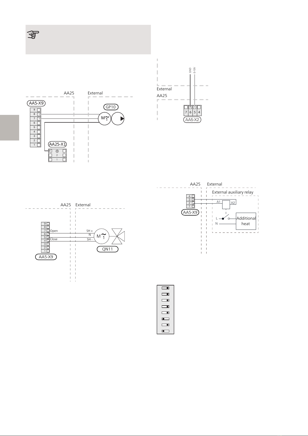
The heat pump/indoor module controls a shunt valve
(EM1-QN11) and a circulation pump (EM1-GP10) via
AXC 40. If the heat pump/indoor module cannot manage
to maintain the correct supply temperature (EB100-
BT25), the additional heat starts. When the temperature
on the boiler sensor (EM1-BT52) exceeds the set value,
the heat pump transmits a signal to the shunt (EM1-
QN11) to open from the additional heat. The shunt (EM1-
QN11) is regulated so that the true supply temperature
agrees with the heat pump’s theoretically calculated set
point value. When the heating demand drops sufficiently
so that additional heat is no longer required, the shunt
(EM1-QN11) closes completely.
Factory-set minimum operating time for the boiler is 12
hours.
The function smart energy source can be selected if you
want to prioritise automatically between heat pump
operation and additional heat versus the best price or
environmental impact.
COMPATIBLE PRODUCTS
• S1155
• S1255
• VVM S320
• VVM S325
PIPE CONNECTIONS
The external circulation pump (EM1-GP10) is placed on
the supply line to the climate system after the temper-
ature sensor (AA35-BT25).
SHUNT VALVE
The shunt valve (EM1-QN11) must be placed on the
supply line to the climate system after the heat pump
according to the outline diagram.
• Connect the supply line from the
heat pump to the external heat
source via the T-pipe to port B on
the shunt valve (closes on reduce
signal).
• Connect the supply line to the climate system from
the shunt valve to the common port AB (always open)
• Connect the supply line from the external additional
heat to the shunt valve to port A (opens on increase
signal).
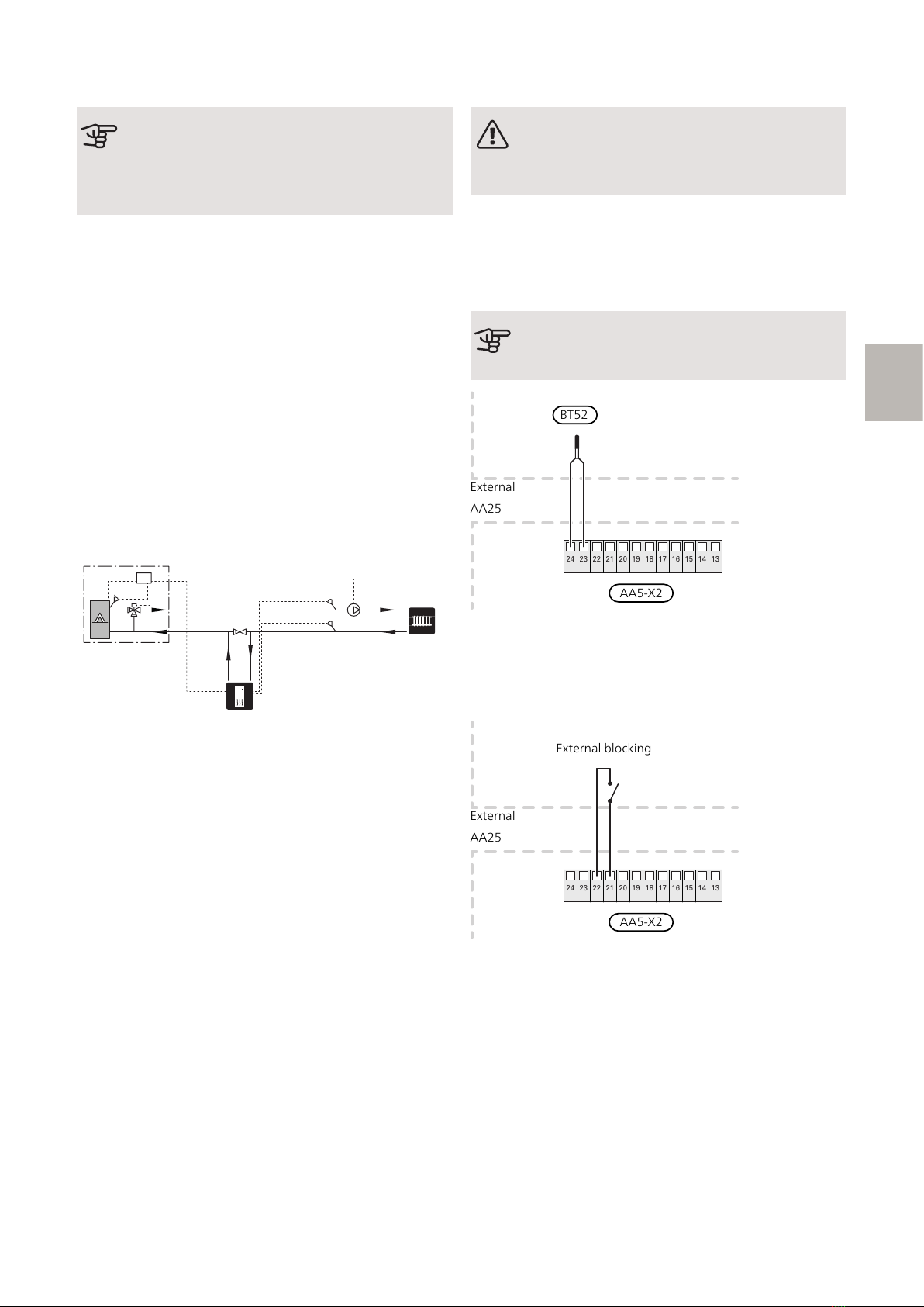
TEMPERATURE SENSOR
• Install the boiler sensor (EM1-BT52) in a suitable loca-
tion in the external additional heat.
• External supply temperature sensor (EB100-BT25,
connected in the heat pump/indoor module) must be
installed on the supply line to the climate system, after
the shunt valve (EM1-QN11).
Install the temperature sensors using cable ties, together
with the heat conducting paste and aluminium tape.
Then insulate with the enclosed insulation tape.
NOTE
To prevent interference, sensor cables to ex-
ternal connections must not be laid close to
high voltage cables.
AXC 40 S-series | GB8
S