manuals.online logo
Brands
  1. Home
  2. •
  3. Brands
  4. •
  5. LG
  6. •
  7. Heat Pump
  8. •
  9. LG 0CVW0-01O User manual

LG 0CVW0-01O User manual

Heat Pump 380-415V + 380V
R410A(50Hz/60Hz)
0CVW0-01O(Replaces 0CVT0-01N)
P/No. : MFL61741615
MULTI V Water IV
Heat Pump
General information
Outside Units
Installation of Outside Units
Special Guide
General information
MULTI V Water IV
Heat Pump
1.Model Names
2.External Appearance
3.Combination of Outside Units
4.Nomenclature
5.Indoor Unit and Outdside Unit Capacity Index
6.Outside Unit Function
2
MULTI V Water IV Heat Pump General information
1. Model Names
Note
1) These Models apply to Europe only.
Power Supply 8HP 10HP 14HP 20HP 16HP1) 18HP1)
3Ø, 380-415, 50Hz
3Ø, 380V, 60Hz 080LAS4 100LAS4 140LAS4 200LAS4 160LAS4 180LAS4
Power Supply 22HP 24HP 28HP 30HP 34HP 40HP
3Ø, 380-415, 50Hz
3Ø, 380V, 60Hz 220LAS4 240LAS4 280LAS4 300LAS4 340LAS4 400LAS4
Power Supply 42HP 44HP 48HP 50HP 54HP 60HP
3Ø, 380-415, 50Hz
3Ø, 380V, 60Hz 420LAS4 440LAS4 480LAS4 500LAS4 540LAS4 600LAS4
Power Supply 62HP 64HP 68HP 70HP 74HP 80HP
3Ø, 380-415, 50Hz
3Ø, 380V, 60Hz 620LAS4 640LAS4 680LAS4 700LAS4 740LAS4 800LAS4
Heat Pump ARWN
3
MULTI V Water IV Heat Pump General information
2. External Appearance
Note
1) These Models apply to Europe only.
Chassis Model Name Model
UWC
ARWN080LAS4
ARWN100LAS4
ARWN140LAS4
ARWN200LAS4
UWC
UWC
ARWN160LAS41)
ARWN180LAS41)
ARWN220LAS4
ARWN240LAS4
ARWN280LAS4
ARWN300LAS4
ARWN340LAS4
ARWN400LAS4
UWC
UWC
UWC
ARWN420LAS4
ARWN440LAS4
ARWN480LAS4
ARWN500LAS4
ARWN540LAS4
ARWN600LAS4
UWC
UWC
UWC
UWC
ARWN620LAS4
ARWN640LAS4
ARWN660LAS4
ARWN700LAS4
ARWN740LAS4
ARWN800LAS4
4
MULTI V Water IV Heat Pump General information
3. Combination of Outside Units
Note
1) These Models apply to Europe only.
Model Number of Units Module(HP)
8101420
ARWN080LAS4 1 1
ARWN100LAS4 1 1
ARWN140LAS4 1 1
ARWN200LAS4 1 1
ARWN160LAS41) 22
ARWN180LAS41) 211
ARWN220LAS4 2 1 1
ARWN240LAS4 2 1 1
ARWN280LAS4 2 2
ARWN300LAS4 2 1 1
ARWN340LAS4 2 1 1
ARWN400LAS4 2 2
ARWN420LAS4 3 1 1 1
ARWN440LAS4 3 1 1 1
ARWN480LAS4 3 2 1
ARWN500LAS4 3 1 2
ARWN540LAS4 3 1 2
ARWN600LAS4 3 3
ARWN620LAS4 4 1 1 2
ARWN640LAS4 4 1 1 2
ARWN680LAS4 4 2 2
ARWN700LAS4 4 1 3
ARWN740LAS4 4 1 3
ARWN800LAS4 4 4
5
MULTI V Water IV Heat Pump General information
4. Nomenclature
Model
Name ARW N 100 L A S 4
No.1234567
No. Signification
1MULTI V Water System with Outside Unit using R410A
2Combination of Inverter Type and Cooling Only or Heat Pump
N: Inverter and H/P
3
Total Cooling Capacity in Horse Power(HP) unit
E X) 10HP ˧'100'
4Electrical Ratings
L: 3Ø, 380 - 415V, 50Hz / 3Ø, 380V, 60Hz
5A : Basic Function
6S : Standard
7Serial number
6
MULTI V Water IV Heat Pump General information
5. Indoor Unit and Outside Unit Capacity Index
5.1 Outside Unit Selection
See the indoor unit capacity tables for given Indoor and outside(outdoor) temperature. Select the unit whose
capacity is the nearest to or greater than given load.
Note
Individual Indoor Unit capacity is subject to change by combination. Actual capacity has to be calculated according
to the combination by using outside unit capacity table.
5.2 Outside Unit Selection
Allowable combinations are indicated below. In general, outside unit can be selected depending on the location of
the unit, zoning and usage of the rooms.
The indoor and outside unit combination is determined by comparing the sum of indoor unit capacity index with
each Outside Unit. It is recommended to be the nearest to 100% combination ratio or to be smaller than that. Refer
the table below. To manage cooling/heating load properly, it's better to be selected the bigger capacity outside unit
rather than the nearest, if the installation space is large enough.
Allowable Total Capacity Index Table of Combined Indoor Units
* Capacity Index is same as the capacity(kW).
Indoor unit capacity index
* Capacity Index is same as the capacity(kW).
Outside Unit
Capacity(HP)
Indoor Unit Combination Ratio
50% 60% 70% 80% 90% 100% 110% 120% 130% 160% 200%
8 11.2 13.4 15.7 17.9 20.2 22.4 24.6 26.9 29.1 35.8 44.8
10 14.0 16.8 19.6 22.4 25.2 28.0 30.8 33.6 36.4 44.8 56.0
14 19.6 23.5 27.4 31.4 35.3 39.2 43.1 47.0 51.0 62.7 78.4
20 28.0 33.6 39.2 44.8 50.4 56.0 61.6 67.2 72.8 89.6 112.0
16 22.4 26.9 31.4 35.8 40.3 44.8 49.3 53.8 58.2 71.7 -
18 25.2 30.2 35.3 40.3 45.4 50.4 55.4 60.5 65.5 80.6 -
22 30.8 37.0 43.1 49.3 55.4 61.6 67.8 73.9 80.1 98.6 -
24 33.6 40.3 47.0 53.8 60.5 67.2 73.9 80.6 87.4 107.5 -
28 39.2 47.0 54.9 62.7 70.6 78.4 86.2 94.1 101.9 125.4 -
30 42.0 50.4 58.8 67.2 75.6 84.0 92.4 100.8 109.2 134.4 -
34 47.6 57.1 66.6 76.2 85.7 95.2 104.7 114.2 123.8 152.3 -
40 56.0 67.2 78.4 89.6 100.8 112.0 123.2 134.4 145.6 179.2 -
42 58.8 70.6 82.3 94.1 105.8 117.6 129.4 141.1 152.9 - -
44 61.6 73.9 86.2 98.6 110.9 123.2 135.5 147.8 160.2 - -
48 67.2 80.6 94.1 107.5 121.0 134.4 147.8 161.3 174.7 - -
50 70.0 84.0 98.0 112.0 126.0 140.0 154.0 168.0 182.0 - -
54 75.6 90.7 105.8 121.0 136.1 151.2 166.3 181.4 196.6 - -
60 84.0 100.8 117.6 134.4 151.2 168.0 184.8 201.6 218.4 - -
62 86.8 104.2 121.5 138.9 156.2 173.6 191.0 208.3 225.7 - -
64 89.6 107.5 125.4 143.4 161.3 179.2 197.1 215.0 233.0 - -
68 95.2 114.2 133.3 152.3 171.4 190.4 209.4 228.5 247.5 - -
70 98.0 117.6 137.2 156.8 176.4 196.0 215.6 235.2 254.8 - -
74 103.6 124.3 145.0 165.8 186.5 207.2 227.9 248.6 269.4 - -
80 112.0 134.4 156.8 179.2 201.6 224.0 246.4 268.8 291.2 - -
Unit Capacity
(Btu/h) 5k 7k 9k 12k 15k 18k 21k 24k 28k 36k 42k 48k 54k 76k 96k
Capacity
Index 1.6 2.2 2.8 3.6 4.5 5.6 6.2 7.1 8.2 10.6 12.3 14.1 15.8 22.4 28.0
5. Indoor Unit and Outside Unit Capacity Index
7
MULTI V Water IV Heat Pump General information
CAUTION
•Ratio of the running Indoor Units to the Outside: Within 10 ~ 100%
•A combination operation over 100% cause to reduce each indoor unit capacity.
Combination ratio (50~200%)
Notes :
1. We can guarantee the operation only within 130% Combination Ratio.
If you want to connect more than 130% combination Ratio, please contact us and discuss the
requirement.
2. In case that operating indoor units ratio to rated capacity of Outside unit is more than 130%, the airflow
should be operated as low step in the all indoor units.
Number of Outside units Combination Ratio
Single Unit 200 %
Two Units combination 160 %
Three or more Units combination 130 %
8
MULTI V Water IV Heat Pump General information
6. Outside Unit Function
Note
1. O : Applied, X : Not applied
Accessory : Ordered and purchased separately the accessory package referring to the model name provided and install at field.
Accessory line-ups varies by region, so check your local catalogue or local sales material.
Note
1. O : Applied, X : Not applied
Accessory : Ordered and purchased separately the accessory package referring to the model name provided and install at field.
Accessory line-ups varies by region, so check your local catalogue or local sales material.
Category Functions Multi V Water IV
Reliability
Defrost / Deicing X
High pressure switch O
Phase protection O
Restart delay (3-minutes) O
Self diagnosis O
Soft start O
Test Run function O
CAC network function Network soluation(LGAP) O
Category Product Etc Multi V Water IV
Central
Controller
AC EZ PQCSZ250S0 - O
AC Ez Touch PACEZA000 - O
AC Smart PACS4B000 AC Smart IV O
PACS5A000 AC Smart 5 O
ACP PACP4B000 ACP IV O
PACP5A000 ACP 5 O
AC Manager PACM4B000 AC Manager IV O
PACM5A000 AC Manager 5 O
Gateway
Cool/Heat Selector PRDSBM Dry Contact For ODU O
Low Ambient Kit PRVC2 From MULTI V 4 series X
AHU Comm. Kit PAHCMR000 Return / Room Air Control O
PAHCMS000 Supply Air Control by DDC O
BACnet PQNFB17C0 ACP BACnet(DC 12V Adapter) O
PQNFB17C1 ACP BACnet(AC 24V) O
Lonworks PLNWKB000 ACP Lonworks(DC 12V Adapter) O
PLNWKB100 ACP Lonworks(AC 24V) O
Lon Translator PLNTRN000 Lon Translator(For Chiller) X
Modbus RTU PMBUSB00A For Multi V 5, ERV X
ETC
PDI PPWRDB000 PDI Standard O
PQNUD1S40 PDI Premium O
ACS IO Module PEXPMB000 - O
Variable Water Flow Valve
Control KIT PWFCKN000 - O
ODU Dry Contact PVDSMN000 - O
Outside Units
MULTI V Water IV
Heat Pump
1.Specifications
2.Dimensions
3.Piping Diagrams
4.Wiring Diagrams
5.Field Wiring
6.Electrical Characteristics
7.Capacity Tables
8.Operation Limits
9.Sound Levels
10.Head loss by Water flow
11.Accessories
2
MULTI V Water IV Heat Pump Outside Units
1. Specifications
System Capacity HP 8 10
Model Name
Combination Unit ARWN080LAS4 ARWN100LAS4
Independent Unit
ARWN080LAS4 ARWN100LAS4
Capacity
Cooling
kW 22.4 28.0
kcal/h 19,300 24,100
Btu/h 76,400 95,900
Heating
kW 25.2 31.5
kcal/h 21,700 27,100
Btu/h 86,000 107,500
Input Cooling kW 3.86 5.09
Heating kW 4.20 5.34
Casing Color Warm Gray , Mornig Gray Warm Gray , Mornig Gray
Compressor
Type Hermetically Sealed Scroll Hermetically Sealed Scroll
Combination (Inverter) x 1 (Inverter) x 1
Piston Displacement cm3/rev 43.8 43.8
Number of revolution rev/min Inverter 3,600 at 60Hz Inverter 3,600 at 60Hz
Motor Output kW 4.2 4.2
Starting Method Direct On Line Direct On Line
Oil Type FVC68D(PVE) FVC68D(PVE)
Heat Exchanger
Type Stainless Steel Plate Stainless Steel Plate
Maximum Pressure
Resistance kgf/cm245 45
Rated Water Flow LPM 77 96
Head Loss kPa 10.7 15.8
Temp. range of
Circulation water
Cooling 10°C ~ 45°C(50°F ~ 113°F) 10°C ~ 45°C(50°F ~ 113°F)
Heating -5°C ~ 45°C(23°F ~ 113°F) -5°C ~ 45°C(23°F ~ 113°F)
Refrigerant
Connecting Pipes
Liquid Pipes mm(inch) 9.52(3/8) 9.52(3/8)
Gas Pipes mm(inch) 22.2(7/8) 22.2(7/8)
Water
Connecting Pipes
Inlet mm PT 40 (Internal Thread) PT 40 (Internal Thread)
Outlet mm PT 40 (Internal Thread) PT 40 (Internal Thread)
Drain Outlet mm PT 20 (External Thread) PT 20 (External Thread)
Dimensions(WxHxD) mm (755 × 997 × 500) x 1 (755 × 997 × 500) x 1
inch (29-23/32 x 39-1/4 x 19-11/16) x 1 (29-23/32 x 39-1/4 x 19-11/16) x 1
Net Weight kg 127 x 1 127 x 1
lbs 280 x 1 280 x 1
Sound Pressure
Level 3)
Cooling dB(A) 47 50
Heating dB(A) 51 53
Sound Power
Level 4)
Cooling dB(A) 59 62
Heating dB(A) 63 65
Transmission Cable(VCTF-SB) No.xmm22C × 1.0 ~ 1.5 2C × 1.0 ~ 1.5
Refrigerant
Name R410A R410A
Charge Amount kg 5.8 5.8
lbs 12.8 12.8
t-CO2 eq 12.108 12.108
Control Device Electronic expansion valve Electronic expansion valve
Power Supply V, Ø, Hz 380 - 400 - 415, 3, 50/60 380 - 400 - 415, 3, 50/60
Running Current Cooling A 6.31 - 5.99 - 5.77 8.32 - 7.90 - 7.61
Heating A 6.86 - 6.52 - 6.28 8.72 - 8.29 - 7.99
Maximum Connectable Number of Indoor Units*** 13(20) 16(25)
Note
1. Due to our policy of innovation some specifications may be changed without notification.
2. Wiring cable size must comply with the applicable local and national codes. And “Electric characteristics” chapter should be considered for electrical
work and design. Especially the power cable and circuit breaker should be selected in accordance with that.
3. Power factor could vary less than ±1% according to the operating conditions.
4. Sound pressure level is measured on the rated condition in the anechoic rooms by ISO 3745 standard.
Sound power level is measured on the rated condition in the reverberation rooms by ISO 3741 standard.
Therefore, these values can be increased owing to ambient conditions during operation.
5. Sound values of combination model are calculated values based on sound results of independent models.
Sound values can be increased owing to ambient or installation conditions during operation.
Sound values of system [dB(A)] = 10*log [10^(A1/10)+ ... +10^(An/10)] , A1~An means sound values of independent models.
6. Performances are based on the following conditions :
• Cooling : Indoor Ambient Temp. 27°CDB / 19°CWB, Water inlet temp. 30°C
• Heating : Indoor Ambient Temp. 20°CDB / 15°CWB, Water Inlet temp. 20°C
• Interconnected Pipe Length is 7.5m and difference of Elevation (Outdoor ~ Indoor Unit) is 0m.
7. *** : The number in parentheses means maximum connectable indoor units in accordance with outdoor units combination (160~200%).
The recommended ratio is 130%.
8. This product contains Fluorinated greenhouse gases.(R410A, GWP(Global warming potential) = 2,087.5)
1. Specifications
3
MULTI V Water IV Heat Pump Outside Units
System Capacity HP 14 20
Model Name
Combination Unit ARWN140LAS4 ARWN200LAS4
Independent Unit
ARWN140LAS4 ARWN200LAS4
Capacity
Cooling
kW 39.2 56.0
kcal/h 33,700 48,200
Btu/h 133,800 191,100
Heating
kW 44.1 63.0
kcal/h 37,900 54,200
Btu/h 150,500 215,000
Input Cooling kW 7.84 11.20
Heating kW 8.17 11.67
Casing Color Warm Gray , Mornig Gray Warm Gray , Mornig Gray
Compressor
Type Hermetically Sealed Scroll Hermetically Sealed Scroll
Combination (Inverter) x 1 (Inverter) x 1
Piston Displacement cm3/rev 43.8 62.1
Number of revolution rev/min Inverter 3,600 at 60Hz Inverter 3,600 at 60Hz
Motor Output kW 4.2 5.3
Starting Method Direct On Line Direct On Line
Oil Type FVC68D(PVE) FVC68D(PVE)
Heat Exchanger
Type Stainless Steel Plate Stainless Steel Plate
Maximum Pressure
Resistance kgf/cm245 45
Rated Water Flow LPM 135 192
Head Loss kPa 28.6 30.1
Temp. range of
Circulation water
Cooling 10°C ~ 45°C(50°F ~ 113°F) 10°C ~ 45°C(50°F ~ 113°F)
Heating -5°C ~ 45°C(23°F ~ 113°F) -5°C ~ 45°C(23°F ~ 113°F)
Refrigerant
Connecting Pipes
Liquid Pipes mm(inch) 12.7(1/2) 12.7(1/2)
Gas Pipes mm(inch) 25.4(1) 28.58(1-1/8)
Water
Connecting Pipes
Inlet mm PT 40 (Internal Thread) PT 40 (Internal Thread)
Outlet mm PT 40 (Internal Thread) PT 40 (Internal Thread)
Drain Outlet mm PT 20 (External Thread) PT 20 (External Thread)
Dimensions(WxHxD) mm (755 × 997 × 500) x 1 (755 × 997 × 500) x 1
inch (29-23/32 x 39-1/4 x 19-11/16) x 1 (29-23/32 x 39-1/4 x 19-11/16) x 1
Net Weight kg 127 x 1 140 x 1
lbs 280 x 1 309 x 1
Sound Pressure
Level 3)
Cooling dB(A) 58 54
Heating dB(A) 57 60
Sound Power
Level 4)
Cooling dB(A) 70 66
Heating dB(A) 69 72
Transmission Cable(VCTF-SB) No.xmm22C × 1.0 ~ 1.5 2C × 1.0 ~ 1.5
Refrigerant
Name R410A R410A
Charge Amount kg 5.8 3.0
lbs 12.8 6.6
t-CO2 eq 12.108 6.263
Control Device Electronic expansion valve Electronic expansion valve
Power Supply V, Ø, Hz 380 - 400 - 415, 3, 50/60 380 - 400 - 415, 3, 50/60
Running Current Cooling A 12.81 - 12.17 - 11.73 18.30 - 17.38 - 16.75
Heating A 13.35 - 12.68 - 12.22 19.07 - 18.11 - 17.46
Maximum Connectable Number of Indoor Units*** 23(35) 32(50)
Note
1. Due to our policy of innovation some specifications may be changed without notification.
2. Wiring cable size must comply with the applicable local and national codes. And “Electric characteristics” chapter should be considered for electrical
work and design. Especially the power cable and circuit breaker should be selected in accordance with that.
3. Power factor could vary less than ±1% according to the operating conditions.
4. Sound pressure level is measured on the rated condition in the anechoic rooms by ISO 3745 standard.
Sound power level is measured on the rated condition in the reverberation rooms by ISO 3741 standard.
Therefore, these values can be increased owing to ambient conditions during operation.
5. Sound values of combination model are calculated values based on sound results of independent models.
Sound values can be increased owing to ambient or installation conditions during operation.
Sound values of system [dB(A)] = 10*log [10^(A1/10)+ ... +10^(An/10)] , A1~An means sound values of independent models.
6. Performances are based on the following conditions :
• Cooling : Indoor Ambient Temp. 27°CDB / 19°CWB, Water inlet temp. 30°C
• Heating : Indoor Ambient Temp. 20°CDB / 15°CWB, Water Inlet temp. 20°C
• Interconnected Pipe Length is 7.5m and difference of Elevation (Outdoor ~ Indoor Unit) is 0m.
7. *** : The number in parentheses means maximum connectable indoor units in accordance with outdoor units combination (160~200%).
The recommended ratio is 130%.
8. This product contains Fluorinated greenhouse gases.(R410A, GWP(Global warming potential) = 2,087.5)
MULTI V Water IV Heat Pump
1. Specifications
4
Outside Units
System Capacity HP 16 18
Model Name
Combination Unit ARWN160LAS4 ARWN180LAS4
Independent Unit
ARWN080LAS4 ARWN100LAS4
ARWN080LAS4 ARWN080LAS4
Capacity
Cooling
kW 44.8 50.4
kcal/h 38,600 43,400
Btu/h 152,800 172,300
Heating
kW 50.4 56.7
kcal/h 43,400 48,800
Btu/h 172,000 193,500
Input Cooling kW 7.72 8.95
Heating kW 8.40 9.54
Casing Color Warm Gray , Mornig Gray Warm Gray , Mornig Gray
Compressor
Type Hermetically Sealed Scroll Hermetically Sealed Scroll
Combination (Inverter) x 2 (Inverter) x 2
Piston Displacement cm3/rev 43.8 + 43.8 43.8 + 43.8
Number of revolution rev/min Inverter 3,600 at 60Hz Inverter 3,600 at 60Hz
Motor Output kW 4.2 + 4.2 4.2 + 4.2
Starting Method Direct On Line Direct On Line
Oil Type FVC68D(PVE) FVC68D(PVE)
Heat Exchanger
Type Stainless Steel Plate Stainless Steel Plate
Maximum Pressure
Resistance kgf/cm245 45
Rated Water Flow LPM 77 + 77 96 + 77
Head Loss kPa 10.7 + 10.7 15.8 + 10.7
Temp. range of
Circulation water
Cooling 10°C ~ 45°C(50°F ~ 113°F) 10°C ~ 45°C(50°F ~ 113°F)
Heating -5°C ~ 45°C(23°F ~ 113°F) -5°C ~ 45°C(23°F ~ 113°F)
Refrigerant
Connecting Pipes
Liquid Pipes mm(inch) 12.7(1/2) 12.7(1/2)
Gas Pipes mm(inch) 28.58(1-1/8) 28.58(1-1/8)
Water
Connecting Pipes
Inlet mm PT 40 + PT 40 (Internal Thread) PT 40 + PT 40 (Internal Thread)
Outlet mm PT 40 + PT 40 (Internal Thread) PT 40 + PT 40 (Internal Thread)
Drain Outlet mm PT 20 (External Thread) PT 20 (External Thread)
Dimensions(WxHxD) mm (755 × 997 × 500) x 2 (755 × 997 × 500) x 2
inch (29-23/32 x 39-1/4 x 19-11/16) x 2 (29-23/32 x 39-1/4 x 19-11/16) x 2
Net Weight kg 127 x 2 127 x 2
lbs 280 x 2 280 x 2
Sound Pressure
Level 3)
Cooling dB(A) 50 52
Heating dB(A) 54 55
Sound Power
Level 4)
Cooling dB(A) 62 64
Heating dB(A) 66 67
Transmission Cable(VCTF-SB) No.xmm22C × 1.0 ~ 1.5 2C × 1.0 ~ 1.5
Refrigerant
Name R410A R410A
Charge Amount kg 5.8 + 5.8 5.8 + 5.8
lbs 12.8 + 12.8 12.8 + 12.8
t-CO2 eq 24.215 24.215
Control Device Electronic expansion valve Electronic expansion valve
Power Supply V, Ø, Hz 380 - 400 - 415, 3, 50/60 380 - 400 - 415, 3, 50/60
Running Current Cooling A 12.61 - 11.98 - 11.55 14.62 - 13.89 - 13.39
Heating A 13.72 - 13.04 - 12.57 15.59 - 14.81 - 14.27
Maximum Connectable Number of Indoor Units*** 26(40) 29(45)
Note
1. Due to our policy of innovation some specifications may be changed without notification.
2. Wiring cable size must comply with the applicable local and national codes. And “Electric characteristics” chapter should be considered for electrical
work and design. Especially the power cable and circuit breaker should be selected in accordance with that.
3. Power factor could vary less than ±1% according to the operating conditions.
4. Sound pressure level is measured on the rated condition in the anechoic rooms by ISO 3745 standard.
Sound power level is measured on the rated condition in the reverberation rooms by ISO 3741 standard.
Therefore, these values can be increased owing to ambient conditions during operation.
5. Sound values of combination model are calculated values based on sound results of independent models.
Sound values can be increased owing to ambient or installation conditions during operation.
Sound values of system [dB(A)] = 10*log [10^(A1/10)+ ... +10^(An/10)] , A1~An means sound values of independent models.
6. Performances are based on the following conditions :
• Cooling : Indoor Ambient Temp. 27°CDB / 19°CWB, Water inlet temp. 30°C
• Heating : Indoor Ambient Temp. 20°CDB / 15°CWB, Water Inlet temp. 20°C
• Interconnected Pipe Length is 7.5m and difference of Elevation (Outdoor ~ Indoor Unit) is 0m.
7. *** : The number in parentheses means maximum connectable indoor units in accordance with outdoor units combination (160~200%).
The recommended ratio is 130%.
8. This product contains Fluorinated greenhouse gases.(R410A, GWP(Global warming potential) = 2,087.5)
1. Specifications
5
MULTI V Water IV Heat Pump Outside Units
System Capacity HP 22 24
Model Name
Combination Unit ARWN220LAS4 ARWN240LAS4
Independent Unit
ARWN080LAS4 ARWN100LAS4
ARWN140LAS4 ARWN140LAS4
Capacity
Cooling
kW 61.6 67.2
kcal/h 53,000 57,800
Btu/h 210,200 229,700
Heating
kW 69.3 75.6
kcal/h 59,600 65,000
Btu/h 236,500 258,000
Input Cooling kW 11.70 12.93
Heating kW 12.37 13.51
Casing Color Warm Gray , Mornig Gray Warm Gray , Mornig Gray
Compressor
Type Hermetically Sealed Scroll Hermetically Sealed Scroll
Combination (Inverter) x 2 (Inverter) x 2
Piston Displacement cm3/rev 43.8 + 43.8 43.8 + 43.8
Number of revolution rev/min Inverter 3,600 at 60Hz Inverter 3,600 at 60Hz
Motor Output kW 4.2 + 4.2 4.2 + 4.2
Starting Method Direct On Line Direct On Line
Oil Type FVC68D(PVE) FVC68D(PVE)
Heat Exchanger
Type Stainless Steel Plate Stainless Steel Plate
Maximum Pressure
Resistance kgf/cm245 45
Rated Water Flow LPM 135 + 77 135 + 96
Head Loss kPa 28.6 + 10.7 28.6 + 15.8
Temp. range of
Circulation water
Cooling 10°C ~ 45°C(50°F ~ 113°F) 10°C ~ 45°C(50°F ~ 113°F)
Heating -5°C ~ 45°C(23°F ~ 113°F) -5°C ~ 45°C(23°F ~ 113°F)
Refrigerant
Connecting Pipes
Liquid Pipes mm(inch) 19.05(3/4) 19.05(3/4)
Gas Pipes mm(inch) 34.9(1-3/8) 34.9(1-3/8)
Water
Connecting Pipes
Inlet mm PT 40 + PT 40 (Internal Thread) PT 40 + PT 40 (Internal Thread)
Outlet mm PT 40 + PT 40 (Internal Thread) PT 40 + PT 40 (Internal Thread)
Drain Outlet mm PT 20 (External Thread) PT 20 (External Thread)
Dimensions(WxHxD) mm (755 × 997 × 500) x 2 (755 × 997 × 500) x 2
inch (29-23/32 x 39-1/4 x 19-11/16) x 2 (29-23/32 x 39-1/4 x 19-11/16) x 2
Net Weight kg 127 x 2 127 x 2
lbs 280 x 2 280 x 2
Sound Pressure
Level 3)
Cooling dB(A) 58 59
Heating dB(A) 58 58
Sound Power
Level 4)
Cooling dB(A) 70 71
Heating dB(A) 70 70
Transmission Cable(VCTF-SB) No.xmm22C × 1.0 ~ 1.5 2C × 1.0 ~ 1.5
Refrigerant
Name R410A R410A
Charge Amount kg 5.8 + 5.8 5.8 + 5.8
lbs 12.8 + 12.8 12.8 + 12.8
t-CO2 eq 24.215 24.215
Control Device Electronic expansion valve Electronic expansion valve
Power Supply V, Ø, Hz 380 - 400 - 415, 3, 50/60 380 - 400 - 415, 3, 50/60
Running Current Cooling A 19.11 - 18.16 - 17.50 21.12 - 20.07 - 19.34
Heating A 20.21 - 19.20 - 18.50 22.07 - 20.97 - 20.21
Maximum Connectable Number of Indoor Units*** 35(44) 39(48)
Note
1. Due to our policy of innovation some specifications may be changed without notification.
2. Wiring cable size must comply with the applicable local and national codes. And “Electric characteristics” chapter should be considered for electrical
work and design. Especially the power cable and circuit breaker should be selected in accordance with that.
3. Power factor could vary less than ±1% according to the operating conditions.
4. Sound pressure level is measured on the rated condition in the anechoic rooms by ISO 3745 standard.
Sound power level is measured on the rated condition in the reverberation rooms by ISO 3741 standard.
Therefore, these values can be increased owing to ambient conditions during operation.
5. Sound values of combination model are calculated values based on sound results of independent models.
Sound values can be increased owing to ambient or installation conditions during operation.
Sound values of system [dB(A)] = 10*log [10^(A1/10)+ ... +10^(An/10)] , A1~An means sound values of independent models.
6. Performances are based on the following conditions :
• Cooling : Indoor Ambient Temp. 27°CDB / 19°CWB, Water inlet temp. 30°C
• Heating : Indoor Ambient Temp. 20°CDB / 15°CWB, Water Inlet temp. 20°C
• Interconnected Pipe Length is 7.5m and difference of Elevation (Outdoor ~ Indoor Unit) is 0m.
7. *** : The number in parentheses means maximum connectable indoor units in accordance with outdoor units combination (160~200%).
The recommended ratio is 130%.
8. This product contains Fluorinated greenhouse gases.(R410A, GWP(Global warming potential) = 2,087.5)
MULTI V Water IV Heat Pump
1. Specifications
6
Outside Units
System Capacity HP 28 30
Model Name
Combination Unit ARWN280LAS4 ARWN300LAS4
Independent Unit
ARWN140LAS4 ARWN200LAS4
ARWN140LAS4 ARWN100LAS4
Capacity
Cooling
kW 78.4 84.0
kcal/h 67,400 72,300
Btu/h 267,600 287,000
Heating
kW 88.2 94.5
kcal/h 75,800 81,200
Btu/h 301,000 322,500
Input Cooling kW 15.68 16.29
Heating kW 16.34 17.01
Casing Color Warm Gray , Mornig Gray Warm Gray , Mornig Gray
Compressor
Type Hermetically Sealed Scroll Hermetically Sealed Scroll
Combination (Inverter) x 2 (Inverter) x 2
Piston Displacement cm3/rev 43.8 + 43.8 62.1 + 43.8
Number of revolution rev/min Inverter 3,600 at 60Hz Inverter 3,600 at 60Hz
Motor Output kW 4.2 + 4.2 5.3 + 4.2
Starting Method Direct On Line Direct On Line
Oil Type FVC68D(PVE) FVC68D(PVE)
Heat Exchanger
Type Stainless Steel Plate Stainless Steel Plate
Maximum Pressure
Resistance kgf/cm245 45
Rated Water Flow LPM 135 + 135 192 + 96
Head Loss kPa 28.6 + 28.6 30.1 + 15.8
Temp. range of
Circulation water
Cooling 10°C ~ 45°C(50°F ~ 113°F) 10°C ~ 45°C(50°F ~ 113°F)
Heating -5°C ~ 45°C(23°F ~ 113°F) -5°C ~ 45°C(23°F ~ 113°F)
Refrigerant
Connecting Pipes
Liquid Pipes mm(inch) 19.05(3/4) 19.05(3/4)
Gas Pipes mm(inch) 34.9(1-3/8) 34.9(1-3/8)
Water
Connecting Pipes
Inlet mm PT 40 + PT 40 (Internal Thread) PT 40 + PT 40 (Internal Thread)
Outlet mm PT 40 + PT 40 (Internal Thread) PT 40 + PT 40 (Internal Thread)
Drain Outlet mm PT 20 (External Thread) PT 20 (External Thread)
Dimensions(WxHxD) mm (755 × 997 × 500) x 2 (755 × 997 × 500) x 2
inch (29-23/32 x 39-1/4 x 19-11/16) x 2 (29-23/32 x 39-1/4 x 19-11/16) x 2
Net Weight kg 127 x 2 (140 x 1) + (127 x 1)
lbs 280 x 2 (309 x 1) + (280 x 1)
Sound Pressure
Level 3)
Cooling dB(A) 59 55
Heating dB(A) 58 61
Sound Power
Level 4)
Cooling dB(A) 72 67
Heating dB(A) 71 73
Transmission Cable(VCTF-SB) No.xmm22C × 1.0 ~ 1.5 2C × 1.0 ~ 1.5
Refrigerant
Name R410A R410A
Charge Amount kg 5.8 + 5.8 3.0 + 5.8
lbs 12.8 + 12.8 6.6 + 12.8
t-CO2 eq 24.215 18.370
Control Device Electronic expansion valve Electronic expansion valve
Power Supply V, Ø, Hz 380 - 400 - 415, 3, 50/60 380 - 400 - 415, 3, 50/60
Running Current Cooling A 25.62 - 24.34 - 23.46 26.61 - 25.28 - 24.37
Heating A 26.69 - 25.36 - 24.44 27.79 - 26.40 - 25.45
Maximum Connectable Number of Indoor Units*** 45(56) 49(60)
Note
1. Due to our policy of innovation some specifications may be changed without notification.
2. Wiring cable size must comply with the applicable local and national codes. And “Electric characteristics” chapter should be considered for electrical
work and design. Especially the power cable and circuit breaker should be selected in accordance with that.
3. Power factor could vary less than ±1% according to the operating conditions.
4. Sound pressure level is measured on the rated condition in the anechoic rooms by ISO 3745 standard.
Sound power level is measured on the rated condition in the reverberation rooms by ISO 3741 standard.
Therefore, these values can be increased owing to ambient conditions during operation.
5. Sound values of combination model are calculated values based on sound results of independent models.
Sound values can be increased owing to ambient or installation conditions during operation.
Sound values of system [dB(A)] = 10*log [10^(A1/10)+ ... +10^(An/10)] , A1~An means sound values of independent models.
6. Performances are based on the following conditions :
• Cooling : Indoor Ambient Temp. 27°CDB / 19°CWB, Water inlet temp. 30°C
• Heating : Indoor Ambient Temp. 20°CDB / 15°CWB, Water Inlet temp. 20°C
• Interconnected Pipe Length is 7.5m and difference of Elevation (Outdoor ~ Indoor Unit) is 0m.
7. *** : The number in parentheses means maximum connectable indoor units in accordance with outdoor units combination (160~200%).
The recommended ratio is 130%.
8. This product contains Fluorinated greenhouse gases.(R410A, GWP(Global warming potential) = 2,087.5)
1. Specifications
7
MULTI V Water IV Heat Pump Outside Units
System Capacity HP 34 40
Model Name
Combination Unit ARWN340LAS4 ARWN400LAS4
Independent Unit
ARWN200LAS4 ARWN200LAS4
ARWN140LAS4 ARWN200LAS4
Capacity
Cooling
kW 95.2 112.0
kcal/h 81,900 96,400
Btu/h 324,900 382,200
Heating
kW 107.1 126.0
kcal/h 92,100 108,400
Btu/h 365,500 429,900
Input Cooling kW 19.04 22.40
Heating kW 19.84 23.34
Casing Color Warm Gray , Mornig Gray Warm Gray , Mornig Gray
Compressor
Type Hermetically Sealed Scroll Hermetically Sealed Scroll
Combination (Inverter) x 2 (Inverter) x 2
Piston Displacement cm3/rev 62.1 + 43.8 62.1 + 62.1
Number of revolution rev/min Inverter 3,600 at 60Hz Inverter 3,600 at 60Hz
Motor Output kW 5.3 + 4.2 5.3 + 5.3
Starting Method Direct On Line Direct On Line
Oil Type FVC68D(PVE) FVC68D(PVE)
Heat Exchanger
Type Stainless Steel Plate Stainless Steel Plate
Maximum Pressure
Resistance kgf/cm245 45
Rated Water Flow LPM 192 + 135 192 + 192
Head Loss kPa 30.1 + 28.6 30.1 + 30.1
Temp. range of
Circulation water
Cooling 10°C ~ 45°C(50°F ~ 113°F) 10°C ~ 45°C(50°F ~ 113°F)
Heating -5°C ~ 45°C(23°F ~ 113°F) -5°C ~ 45°C(23°F ~ 113°F)
Refrigerant
Connecting Pipes
Liquid Pipes mm(inch) 19.05(3/4) 19.05(3/4)
Gas Pipes mm(inch) 34.9(1-3/8) 41.3(1-5/8)
Water
Connecting Pipes
Inlet mm PT 40 + PT 40 (Internal Thread) PT 40 + PT 40 (Internal Thread)
Outlet mm PT 40 + PT 40 (Internal Thread) PT 40 + PT 40 (Internal Thread)
Drain Outlet mm PT 20 (External Thread) PT 20 (External Thread)
Dimensions(WxHxD) mm (755 × 997 × 500) x 2 (755 × 997 × 500) x 2
inch (29-23/32 x 39-1/4 x 19-11/16) x 2 (29-23/32 x 39-1/4 x 19-11/16) x 2
Net Weight kg (140 x 1) + (127 x 1) 140 x 2
lbs (309 x 1) + (280 x 1) 309 x 2
Sound Pressure
Level 3)
Cooling dB(A) 59 55
Heating dB(A) 61 61
Sound Power
Level 4)
Cooling dB(A) 72 68
Heating dB(A) 74 74
Transmission Cable(VCTF-SB) No.xmm22C × 1.0 ~ 1.5 2C × 1.0 ~ 1.5
Refrigerant
Name R410A R410A
Charge Amount kg 3.0 + 5.8 3.0 + 3.0
lbs 6.6 + 12.8 6.6 + 6.6
t-CO2 eq 18.370 12.525
Control Device Electronic expansion valve Electronic expansion valve
Power Supply V, Ø, Hz 380 - 400 - 415, 3, 50/60 380 - 400 - 415, 3, 50/60
Running Current Cooling A 31.11 - 29.55 - 28.48 36.59 - 34.77 - 33.51
Heating A 32.41 - 30.79 - 29.68 38.13 - 36.22 - 34.91
Maximum Connectable Number of Indoor Units*** 55(64) 64
Note
1. Due to our policy of innovation some specifications may be changed without notification.
2. Wiring cable size must comply with the applicable local and national codes. And “Electric characteristics” chapter should be considered for electrical
work and design. Especially the power cable and circuit breaker should be selected in accordance with that.
3. Power factor could vary less than ±1% according to the operating conditions.
4. Sound pressure level is measured on the rated condition in the anechoic rooms by ISO 3745 standard.
Sound power level is measured on the rated condition in the reverberation rooms by ISO 3741 standard.
Therefore, these values can be increased owing to ambient conditions during operation.
5. Sound values of combination model are calculated values based on sound results of independent models.
Sound values can be increased owing to ambient or installation conditions during operation.
Sound values of system [dB(A)] = 10*log [10^(A1/10)+ ... +10^(An/10)] , A1~An means sound values of independent models.
6. Performances are based on the following conditions :
• Cooling : Indoor Ambient Temp. 27°CDB / 19°CWB, Water inlet temp. 30°C
• Heating : Indoor Ambient Temp. 20°CDB / 15°CWB, Water Inlet temp. 20°C
• Interconnected Pipe Length is 7.5m and difference of Elevation (Outdoor ~ Indoor Unit) is 0m.
7. *** : The number in parentheses means maximum connectable indoor units in accordance with outdoor units combination (160~200%).
The recommended ratio is 130%.
8. This product contains Fluorinated greenhouse gases.(R410A, GWP(Global warming potential) = 2,087.5)
MULTI V Water IV Heat Pump
1. Specifications
8
Outside Units
System Capacity HP 42 44
Model Name
Combination Unit ARWN420LAS4 ARWN440LAS4
Independent Unit
ARWN200LAS4 ARWN200LAS4
ARWN140LAS4 ARWN140LAS4
ARWN080LAS4 ARWN100LAS4
Capacity
Cooling
kW 117.6 123.2
kcal/h 101,200 106,000
Btu/h 401,300 420,800
Heating
kW 132.3 138.6
kcal/h 113,800 119,200
Btu/h 451,500 473,000
Input Cooling kW 22.90 24.13
Heating kW 24.04 25.18
Casing Color Warm Gray , Mornig Gray Warm Gray , Mornig Gray
Compressor
Type Hermetically Sealed Scroll Hermetically Sealed Scroll
Combination (Inverter) x 3 (Inverter) x 3
Piston Displacement cm3/rev 62.1 + 43.8 + 43.8 62.1 + 43.8 + 43.8
Number of revolution rev/min Inverter 3,600 at 60Hz Inverter 3,600 at 60Hz
Motor Output kW 5.3 + 4.2 + 4.2 5.3 + 4.2 + 4.2
Starting Method Direct On Line Direct On Line
Oil Type FVC68D(PVE) FVC68D(PVE)
Heat Exchanger
Type Stainless Steel Plate Stainless Steel Plate
Maximum Pressure
Resistance kgf/cm245 45
Rated Water Flow LPM 192 + 135 + 77 192 + 135 + 96
Head Loss kPa 30.1 + 28.6 + 10.7 30.1 + 28.6 + 15.8
Temp. range of
Circulation water
Cooling 10°C ~ 45°C(50°F ~ 113°F) 10°C ~ 45°C(50°F ~ 113°F)
Heating -5°C ~ 45°C(23°F ~ 113°F) -5°C ~ 45°C(23°F ~ 113°F)
Refrigerant
Connecting Pipes
Liquid Pipes mm(inch) 19.05(3/4) 19.05(3/4)
Gas Pipes mm(inch) 41.3(1-5/8) 41.3(1-5/8)
Water
Connecting Pipes
Inlet mm PT 40 + PT 40 + PT 40
(Internal Thread)
PT 40 + PT 40 + PT 40
(Internal Thread)
Outlet mm PT 40 + PT 40 + PT 40
(Internal Thread)
PT 40 + PT 40 + PT 40
(Internal Thread)
Drain Outlet mm PT 20 (External Thread) PT 20 (External Thread)
Dimensions(WxHxD) mm (755 × 997 × 500) x 3 (755 × 997 × 500) x 3
inch (29-23/32 x 39-1/4 x 19-11/16) x 3 (29-23/32 x 39-1/4 x 19-11/16) x 3
Net Weight kg (140 x 1) + (127 X 2) (140 x 1) + (127 X 2)
lbs (309 x 1) + (280 X 2) (309 x 1) + (280 X 2)
Sound Pressure
Level 3)
Cooling dB(A) 60 60
Heating dB(A) 62 62
Sound Power
Level 4)
Cooling dB(A) 72 72
Heating dB(A) 74 74
Transmission Cable(VCTF-SB) No.xmm22C × 1.0 ~ 1.5 2C × 1.0 ~ 1.5
Refrigerant
Name R410A R410A
Charge Amount kg 3.0 + 5.8 + 5.8 3.0 + 5.8 + 5.8
lbs 6.6 + 12.8 + 12.8 6.6 + 12.8 + 12.8
t-CO2 eq 30.478 30.478
Control Device Electronic expansion valve Electronic expansion valve
Power Supply V, Ø, Hz 380 - 400 - 415, 3, 50/60 380 - 400 - 415, 3, 50/60
Running Current Cooling A 37.41 - 35.54 - 34.26 39.42 - 37.45 - 36.10
Heating A 39.27 - 37.31 - 35.96 41.14 - 39.08 - 37.67
Maximum Connectable Number of Indoor Units*** 64 64
Note
1. Due to our policy of innovation some specifications may be changed without notification.
2. Wiring cable size must comply with the applicable local and national codes. And “Electric characteristics” chapter should be considered for electrical
work and design. Especially the power cable and circuit breaker should be selected in accordance with that.
3. Power factor could vary less than ±1% according to the operating conditions.
4. Sound pressure level is measured on the rated condition in the anechoic rooms by ISO 3745 standard.
Sound power level is measured on the rated condition in the reverberation rooms by ISO 3741 standard.
Therefore, these values can be increased owing to ambient conditions during operation.
5. Sound values of combination model are calculated values based on sound results of independent models.
Sound values can be increased owing to ambient or installation conditions during operation.
Sound values of system [dB(A)] = 10*log [10^(A1/10)+ ... +10^(An/10)] , A1~An means sound values of independent models.
6. Performances are based on the following conditions :
• Cooling : Indoor Ambient Temp. 27°CDB / 19°CWB, Water inlet temp. 30°C
• Heating : Indoor Ambient Temp. 20°CDB / 15°CWB, Water Inlet temp. 20°C
• Interconnected Pipe Length is 7.5m and difference of Elevation (Outdoor ~ Indoor Unit) is 0m.
7. *** : The number in parentheses means maximum connectable indoor units in accordance with outdoor units combination (160~200%).
The recommended ratio is 130%.
8. This product contains Fluorinated greenhouse gases.(R410A, GWP(Global warming potential) = 2,087.5)
1. Specifications
9
MULTI V Water IV Heat Pump Outside Units
System Capacity HP 48 50
Model Name
Combination Unit ARWN480LAS4 ARWN500LAS4
Independent Unit
ARWN200LAS4 ARWN200LAS4
ARWN140LAS4 ARWN200LAS4
ARWN140LAS4 ARWN100LAS4
Capacity
Cooling
kW 134.4 140.0
kcal/h 115,600 120,500
Btu/h 458,700 478,100
Heating
kW 151.2 157.5
kcal/h 130,000 135,500
Btu/h 516,000 537,500
Input Cooling kW 26.88 27.49
Heating kW 28.01 28.68
Casing Color Warm Gray , Mornig Gray Warm Gray , Mornig Gray
Compressor
Type Hermetically Sealed Scroll Hermetically Sealed Scroll
Combination (Inverter) x 3 (Inverter) x 3
Piston Displacement cm3/rev 62.1 + 43.8 + 43.8 62.1 + 62.1 + 43.8
Number of revolution rev/min Inverter 3,600 at 60Hz Inverter 3,600 at 60Hz
Motor Output kW 5.3 + 4.2 + 4.2 5.3 + 5.3 + 4.2
Starting Method Direct On Line Direct On Line
Oil Type FVC68D(PVE) FVC68D(PVE)
Heat Exchanger
Type Stainless Steel Plate Stainless Steel Plate
Maximum Pressure
Resistance kgf/cm245 45
Rated Water Flow LPM 192 + 135 + 135 192 + 192 + 96
Head Loss kPa 30.1 + 28.6 + 28.6 30.1 + 30.1 + 15.8
Temp. range of
Circulation water
Cooling 10°C ~ 45°C(50°F ~ 113°F) 10°C ~ 45°C(50°F ~ 113°F)
Heating -5°C ~ 45°C(23°F ~ 113°F) -5°C ~ 45°C(23°F ~ 113°F)
Refrigerant
Connecting Pipes
Liquid Pipes mm(inch) 19.05(3/4) 19.05(3/4)
Gas Pipes mm(inch) 41.3(1-5/8) 41.3(1-5/8)
Water
Connecting Pipes
Inlet mm PT 40 + PT 40 + PT 40
(Internal Thread)
PT 40 + PT 40 + PT 40
(Internal Thread)
Outlet mm PT 40 + PT 40 + PT 40
(Internal Thread)
PT 40 + PT 40 + PT 40
(Internal Thread)
Drain Outlet mm PT 20 (External Thread) PT 20 (External Thread)
Dimensions(WxHxD) mm (755 × 997 × 500) x 3 (755 × 997 × 500) x 3
inch (29-23/32 x 39-1/4 x 19-11/16) x 3 (29-23/32 x 39-1/4 x 19-11/16) x 3
Net Weight kg (140 x 1) + (127 X 2) (140 x 2) + (127 X 1)
lbs (309 x 1) + (280 X 2) (309 x 2) + (280X1)
Sound Pressure
Level 3)
Cooling dB(A) 60 58
Heating dB(A) 62 63
Sound Power
Level 4)
Cooling dB(A) 74 70
Heating dB(A) 76 75
Transmission Cable(VCTF-SB) No.xmm22C × 1.0 ~ 1.5 2C × 1.0 ~ 1.5
Refrigerant
Name R410A R410A
Charge Amount kg 3.0 + 5.8 + 5.8 3.0 + 3.0 + 5.8
lbs 6.6 + 12.8 + 12.8 6.6 + 6.6 + 12.8
t-CO2 eq 30.478 24.633
Control Device Electronic expansion valve Electronic expansion valve
Power Supply V, Ø, Hz 380 - 400 - 415, 3, 50/60 380 - 400 - 415, 3, 50/60
Running Current Cooling A 43.91 - 41.72 - 40.21 44.91 - 42.66 - 41.12
Heating A 45.76 - 43.47 - 41.90 46.85 - 44.51 - 42.90
Maximum Connectable Number of Indoor Units*** 64 64
Note
1. Due to our policy of innovation some specifications may be changed without notification.
2. Wiring cable size must comply with the applicable local and national codes. And “Electric characteristics” chapter should be considered for electrical
work and design. Especially the power cable and circuit breaker should be selected in accordance with that.
3. Power factor could vary less than ±1% according to the operating conditions.
4. Sound pressure level is measured on the rated condition in the anechoic rooms by ISO 3745 standard.
Sound power level is measured on the rated condition in the reverberation rooms by ISO 3741 standard.
Therefore, these values can be increased owing to ambient conditions during operation.
5. Sound values of combination model are calculated values based on sound results of independent models.
Sound values can be increased owing to ambient or installation conditions during operation.
Sound values of system [dB(A)] = 10*log [10^(A1/10)+ ... +10^(An/10)] , A1~An means sound values of independent models.
6. Performances are based on the following conditions :
• Cooling : Indoor Ambient Temp. 27°CDB / 19°CWB, Water inlet temp. 30°C
• Heating : Indoor Ambient Temp. 20°CDB / 15°CWB, Water Inlet temp. 20°C
• Interconnected Pipe Length is 7.5m and difference of Elevation (Outdoor ~ Indoor Unit) is 0m.
7. *** : The number in parentheses means maximum connectable indoor units in accordance with outdoor units combination (160~200%).
The recommended ratio is 130%.
8. This product contains Fluorinated greenhouse gases.(R410A, GWP(Global warming potential) = 2,087.5)
MULTI V Water IV Heat Pump
1. Specifications
10
Outside Units
System Capacity HP 54 60
Model Name
Combination Unit ARWN540LAS4 ARWN600LAS4
Independent Unit
ARWN200LAS4 ARWN200LAS4
ARWN140LAS4 ARWN200LAS4
Capacity
Cooling
kW 151.2 168.0
kcal/h 130,100 144,600
Btu/h 516,000 573,300
Heating
kW 170.1 189.0
kcal/h 146,300 162,600
Btu/h 580,500 645,000
Input Cooling kW 30.24 33.60
Heating kW 31.51 35.01
Casing Color Warm Gray , Mornig Gray Warm Gray , Mornig Gray
Compressor
Type Hermetically Sealed Scroll Hermetically Sealed Scroll
Combination (Inverter) x 3 (Inverter) x 3
Piston Displacement cm3/rev 62.1 + 62.1 + 43.8 62.1 + 62.1 + 62.1
Number of revolution rev/min Inverter 3,600 at 60Hz Inverter 3,600 at 60Hz
Motor Output kW 5.3 + 5.3 + 4.2 5.3 + 5.3 + 5.3
Starting Method Direct On Line Direct On Line
Oil Type FVC68D(PVE) FVC68D(PVE)
Heat Exchanger
Type Stainless Steel Plate Stainless Steel Plate
Maximum Pressure
Resistance kgf/cm245 45
Rated Water Flow LPM 192 + 192 + 135 192 + 192+ 192
Head Loss kPa 30.1 + 28.6 + 28.6 30.1 + 30.1 + 30.1
Temp. range of
Circulation water
Cooling 10°C ~ 45°C(50°F ~ 113°F) 10°C ~ 45°C(50°F ~ 113°F)
Heating -5°C ~ 45°C(23°F ~ 113°F) -5°C ~ 45°C(23°F ~ 113°F)
Refrigerant
Connecting Pipes
Liquid Pipes mm(inch) 19.05(3/4) 19.05(3/4)
Gas Pipes mm(inch) 41.3(1-5/8) 41.3(1-5/8)
Water
Connecting Pipes
Inlet mm PT 40 + PT 40 + PT 40
(Internal Thread)
PT 40 + PT 40 + PT 40
(Internal Thread)
Outlet mm PT 40 + PT 40 + PT 40
(Internal Thread)
PT 40 + PT 40 + PT 40
(Internal Thread)
Drain Outlet mm PT 20 (External Thread) PT 20 (External Thread)
Dimensions(WxHxD) mm (755 × 997 × 500) x 3 (755 × 997 × 500) x 3
inch (29-23/32 x 39-1/4 x 19-11/16) x 3 (29-23/32 x 39-1/4 x 19-11/16) x 3
Net Weight kg (140 x 2) + (127 X 1) 140 x 3
lbs (309 x 2) + (280X1) 309 x 3
Sound Pressure
Level 3)
Cooling dB(A) 60 56
Heating dB(A) 62 62
Sound Power
Level 4)
Cooling dB(A) 74 70
Heating dB(A) 76 76
Transmission Cable(VCTF-SB) No.xmm22C × 1.0 ~ 1.5 2C × 1.0 ~ 1.5
Refrigerant
Name R410A R410A
Charge Amount kg 3.0 + 3.0 + 5.8 3.0 + 3.0 + 3.0
lbs 6.6 + 6.6 + 12.8 6.6 + 6.6 + 6.6
t-CO2 eq 24.633 18.788
Control Device Electronic expansion valve Electronic expansion valve
Power Supply V, Ø, Hz 380 - 400 - 415, 3, 50/60 380 - 400 - 415, 3, 50/60
Running Current Cooling A 49.40 - 46.93 - 45.24 54.89 - 52.15 - 50.26
Heating A 51.48 - 48.90 - 47.14 57.20 - 54.34 - 52.37
Maximum Connectable Number of Indoor Units*** 64 64
Note
1. Due to our policy of innovation some specifications may be changed without notification.
2. Wiring cable size must comply with the applicable local and national codes. And “Electric characteristics” chapter should be considered for electrical
work and design. Especially the power cable and circuit breaker should be selected in accordance with that.
3. Power factor could vary less than ±1% according to the operating conditions.
4. Sound pressure level is measured on the rated condition in the anechoic rooms by ISO 3745 standard.
Sound power level is measured on the rated condition in the reverberation rooms by ISO 3741 standard.
Therefore, these values can be increased owing to ambient conditions during operation.
5. Sound values of combination model are calculated values based on sound results of independent models.
Sound values can be increased owing to ambient or installation conditions during operation.
Sound values of system [dB(A)] = 10*log [10^(A1/10)+ ... +10^(An/10)] , A1~An means sound values of independent models.
6. Performances are based on the following conditions :
• Cooling : Indoor Ambient Temp. 27°CDB / 19°CWB, Water inlet temp. 30°C
• Heating : Indoor Ambient Temp. 20°CDB / 15°CWB, Water Inlet temp. 20°C
• Interconnected Pipe Length is 7.5m and difference of Elevation (Outdoor ~ Indoor Unit) is 0m.
7. *** : The number in parentheses means maximum connectable indoor units in accordance with outdoor units combination (160~200%).
The recommended ratio is 130%.
8. This product contains Fluorinated greenhouse gases.(R410A, GWP(Global warming potential) = 2,087.5)

This manual suits for next models

2

Other LG Heat Pump manuals

LG MULTI F MAX Installation and operation manual

LG

LG MULTI F MAX Installation and operation manual

LG ARWN038GA2 User manual

LG

LG ARWN038GA2 User manual

LG MULTI V WATER 5 ARW Series Installation and operation manual

LG

LG MULTI V WATER 5 ARW Series Installation and operation manual

LG THERMA V User manual

LG

LG THERMA V User manual

LG MULTI V ARUN050LMS0 Product guide

LG

LG MULTI V ARUN050LMS0 Product guide

LG MULTI V S 0CVM0-05A Product guide

LG

LG MULTI V S 0CVM0-05A Product guide

LG Therma V PHLLA User manual

LG

LG Therma V PHLLA User manual

LG WH20S F5 User manual

LG

LG WH20S F5 User manual

LG Multi V BR Series User manual

LG

LG Multi V BR Series User manual

LG A2UW18GFAC User manual

LG

LG A2UW18GFAC User manual

LG THERMA V Air-to-Water Heat Pump User manual

LG

LG THERMA V Air-to-Water Heat Pump User manual

LG 5BPU0-02D Product guide

LG

LG 5BPU0-02D Product guide

LG MULTI V LRNN Series User manual

LG

LG MULTI V LRNN Series User manual

LG THERMA V AHNW16606B0 User manual

LG

LG THERMA V AHNW16606B0 User manual

LG MULTI F Series User manual

LG

LG MULTI F Series User manual

LG LC248HV Installation and operation manual

LG

LG LC248HV Installation and operation manual

LG THERMA V HM093MR User manual

LG

LG THERMA V HM093MR User manual

LG LC098HV4 Installation and operation manual

LG

LG LC098HV4 Installation and operation manual

LG ARNU18GBHA1 User manual

LG

LG ARNU18GBHA1 User manual

LG Multi V water mini Series Owner's manual

LG

LG Multi V water mini Series Owner's manual

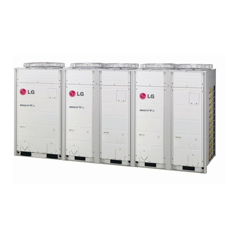
LG MULTI V WATER IV ARWN080LAS4 Product guide
LG

LG MULTI V WATER IV ARWN080LAS4 Product guide

LG AHNW146A0 User manual

LG

LG AHNW146A0 User manual

LG THERMA V User manual

LG

LG THERMA V User manual

LG THERMA V User manual

LG

LG THERMA V User manual

Popular Heat Pump manuals by other brands

Atlantic alfea S S5 Installation and operating manual

Atlantic

Atlantic alfea S S5 Installation and operating manual

Hayward HeatRelax HPR06M Installation instructions manual

Hayward

Hayward HeatRelax HPR06M Installation instructions manual

Bard QW Series installation instructions

Bard

Bard QW Series installation instructions

Aquacal TropiCal T115 Product specification

Aquacal

Aquacal TropiCal T115 Product specification

Bryant 575Jx08G/H Series Installation, Start-Up and Service Instructions

Bryant

Bryant 575Jx08G/H Series Installation, Start-Up and Service Instructions

Chigo CKST-4SH user manual

Chigo

Chigo CKST-4SH user manual

Trane CAUC-C80 Installation operation & maintenance

Trane

Trane CAUC-C80 Installation operation & maintenance

Hamilton Engineering EVO 299 Maintenance procedures

Hamilton Engineering

Hamilton Engineering EVO 299 Maintenance procedures

Alto AHH-R075/ALH Operation manual

Alto

Alto AHH-R075/ALH Operation manual

SUPREME heatseeker nova user manual

SUPREME

SUPREME heatseeker nova user manual

Trane 4TWR4 Use and care

Trane

Trane 4TWR4 Use and care

Maritime Geothermal TF Series Installation and service manual

Maritime Geothermal

Maritime Geothermal TF Series Installation and service manual

Carrier 50XZ024 manual

Carrier

Carrier 50XZ024 manual

Dimplex LI 11ME Installation and operating instructions

Dimplex

Dimplex LI 11ME Installation and operating instructions

Ferroli RVL 16 Series Installation and operation manual

Ferroli

Ferroli RVL 16 Series Installation and operation manual

Carrier COMFORT SERIES 25HCB3 Product data

Carrier

Carrier COMFORT SERIES 25HCB3 Product data

Carrier 30XW Installation, operation and maintenance instructions

Carrier

Carrier 30XW Installation, operation and maintenance instructions

Heat Controller Energy Knight HMC30AS-1 installation instructions

Heat Controller

Heat Controller Energy Knight HMC30AS-1 installation instructions

manuals.online logo
manuals.online logoBrands
  • About & Mission
  • Contact us
  • Privacy Policy
  • Terms and Conditions

Copyright 2025 Manuals.Online. All Rights Reserved.