Heatcraft intelliGen H-IM-iFM User manual
H-IM-iFM July 2023 Part No. 25011801
intelliGen Field Mount
(iFM) Kit
Installation and Operation Manual
intelliGen Components
intelliGen Board (iRC) Layout ................................ 2
intelliGen User Interface (iRCUI) Layout ................ 3
IntelliGen Remote Access Cards (iWC, iIC)............ 3
Installation & Wiring
Installation Tips .................................................... 4
Evaporator Unit ................................................... 4
Condensing Unit by Others .................................. 4
Special Condensing Unit by Heatcraft ................... 5
Refrigerant Line Brazing ...................................... 5
Leak Testing ....................................................... 5
Refrigerant Charging ............................................ 5
Power Supply....................................................... 5
Wiring .............................................................. 5-7
Wiring Terminals .................................................. 8
Wiring Diagrams .............................................9-20
Installation Checklist ......................................... 21
Start-up & Operation
Check-Out Installation........................................ 22
Initial Power On ................................................. 22
System Start-up ............................................... 23
Cooling Start-up Operation ............................... 23
Home Menus & PIN............................................. 24
Navigation, System & Local .............................. 24
Menus and Settings .....................................25-31
Cooling Sequence of Operation .......................... 32
Defrost Sequence of Operation............................ 33
Table of Contents
intelliGen Field Mount (iFM) Kits ...................... 2
Components needed for Installation ................2
Preparation for Installation ..............................3
Components Included in Kit..........................4-7
Components Not Included in Kit ...................... 8
Electronic Expansion Valve EXV ....................8-9
Field Wire Connections.................................. 10
Unit Cooler Product Families Supported......... 11
Main Control Board (iRC) Layout.................... 12
User Interface (iRCUI) Layout......................... 13
Optional Remote Access Cards...................... 13
Typical Wiring Diagrams........................... 14-15
Remote Mount intelliGen Controller .......... 16-17
Components Installation in Unit Cooler ..... 18-21
Retrofit of an Existing Unit Cooler .................. 22
Check-Out Installation................................... 23
System Start Ups ..................................... 24-25
iFM Kit Accessories....................................... 26
Scan QR code to view the
manual online

2
intelliGen Field Mount (iFM) Kits for
Unit Coolers
The intelliGen™Field Mount Kit is designed to install in the
field for new unit coolers without factory mounted controls
or retrofit of existing unit coolers with mechanical control
to upgrade to electronic control. The intelliGen control can
be remote mounted up to 40 feet from the unit cooler at a
convenient location for easy access. The intelliGen control is
pre-assembled in a IP65 rated housing for both indoor and
Components Needed for Installation
The iFM kit comes with the intelliGen controller, 3 tempera-
ture sensors, 1 pressure transducer with cable, 1 terminal
board and mounting accessories. The temperature sensors
and pressure transducer cable are 25 feet in length. Other
wire lengths are available as optional kit in separate part
numbers. See Components Included section for details.
There are individual system dependent components are
not included but required for each installation. These
components include the 24VAC control power transformer,
the electronic expansion valve (EXV), the power wires for
control power, fan motors, defrost heaters and solenoid
outdoor applications. It supports Heatcraft’s major unit cooler
product lines such as the Low Profile, Center Mount and
Low Velocity Center Mount, Medium Profile, High Profile
Large Unit Coolers and others. It is universal fit for field
mount and retrofit for all air and electric defrost unit coolers
for refrigeration.
valve. Not all applications require defrost heaters and solenoid
valve, check the system requirement for wiring needs.
See Components NOT Included section for details and avail-
ability options.
Field wire runs between the intelliGen controller and the unit
cooler should be in conduits and have to meet local building
and electric code requirements. Conduit fittings are needed
for the conduit runs. Please conduct a site survey and review
your local codes for detailed requirements prior to installation.
Low voltage and communication wires need to run in separate
conduit from the high voltage wires to minimize interference.
Field Mount Kit Includes
Pre-Assembled, Wall-Mount
Controller Assembly
- intelliGen™ main control board and
display board inside water resistant
plastic housing with connection cable
3X Temperature Sensors (with 25ft leads)
Pressure Transducer with Harness (25ft)
Terminal Board with Screws
and Accessories
Easy-to-Follow Wiring Diagram
User Manual
intelliGen™ controllers are the simple,
intuitive alternative for refrigeration control.
Easy-to-read 3-color LED status bar
Text message display
Easy setup and no more service codes to look up
Simple turn & press navigation knob
Optional webserver and integration cards
One per system, supports up to 8 unit-coolers
Free remote monitoring with webserver upgrade*
Energy-saving Smart Defrost
* Requires optional intelliGen Webserver card or BMS integration card. FPO FOR FINAL LEGAL Lorem ipsum dolor sit amet, consectetuer adipiscing elit,
tincidunt ut laoreet dolore magna aliquam erat volutpat. Ut wisi enim ad minim veniam, quis nostrud exerci tation ullamcorper suscipit lobortis nisl ut
aliquip ex ea commodo consequat. Duis autem vel eum iriure dolor in hendrerit in vulputate velit esse molestie consequat, vel illum dolore eu feugiat
nulla facilisis at vero eros et accumsan et iusto odio dignissim qui blandit praesent luptatum zzril delenit augue duis dolore.
Universal Field-Mount
Refrigeration Controller
with temperature sensors and pressure transducer kit
Simple setup
with intelliGen™
Quick Start
Intuitive and
easy to use
user interface
On board
USB port for
data logging and
software update
Remote
monitoring
with optional
webserver card*
Support up to
8 unit coolers in a
single system
Connect. Control. Diagnose. Relax.
Scan the QR Code
or visit
intelliGenControls.com
INTUITIVE
design
SIMPLE
setup
SMART
servicing
User-friendly
interface for easy
install and service.
Quick Start system
configuration allows for
setup in minutes, not hours.
Light Bar Alerts
Color coded LED immediately
shows the status of your system.
Full-Text Display
Guided text instruction
for setup and service.
Quick Menu Buttons
Establish preferred settings
and quickly make changes.
Turn & Press Knob
Quickly navigate system
configuration and servicing.
Ready-to-Mount
Plastic Housing
Waterproof seal for indoor &
outdoor applications.
All electronics pre-installed.
Reduce diagnosis, service
and downtime with intuitive
user interface, data logging
and optional remote monitoring.
The intelliGen™ Field Mount kit
is the simple, easy-to-install
solution for remote refrigeration
monitoring and control.
HARNESS
Sensor Harnesses (X3)
Pressure Transducer
Harness (X1)
ACCESSORIES
Screws and
Installation
Accessories
CONTROLLER
intelliGen™ Controller
Pre-Installed in IP64
Water-Resistant Case
ICON
TO
COME
IMPORTANT!
Additional components are required for
proper iFM installation. Be sure you have
compatible version of the following parts.
Recommended Tools for Installation
Scan QR Code for details and
to view our installation video
or visit
intelliGenControls.com
24VAC Transformer
EEV Kit with Cable
High Voltage Control Harness
Uni-bit
Power drill & drill bits
5/16” nut driver
7/16” & 5/8” wrenches
Phillips screwdriver
Precision slotted screwdriver
Wire Stripper/Crimper
Multimeter
intelliGen Field Mount (iFM) Kits

3
intelliGen Field Mount (iFM) Kits
Preparation for Installation
Tools Use Tools Use
Slotted Screwdrive Wrench, 7/16 and
5/8
Phillips
Screwdriver Adjustable Wrench
Precision Slotted
Screwdrive
Wire Stripper /
Crimper
5/16 Nut Driver Multimeter
Power Drill & Drill
Bits Marker
Needed Tools
Tools Use Tools Use
Slotted Screwdrive
Wrench, 7/16 and
5/8
Phillips
Screwdriver Adjustable Wrench
Precision Slotted
Screwdrive
Wire Stripper /
Crimper
5/16 Nut Driver Multimeter
Power Drill & Drill
Bits Marker
Needed Tools
Tools Use Tools Use
Slotted Screwdrive
Wrench, 7/16 and
5/8
Phillips
Screwdriver Adjustable Wrench
Precision Slotted
Screwdrive
Wire Stripper /
Crimper
5/16 Nut Driver Multimeter
Power Drill & Drill
Bits Marker
Needed Tools
Tools Use Tools Use
Slotted Screwdrive
Wrench, 7/16 and
5/8
Phillips
Screwdriver Adjustable Wrench
Precision Slotted
Screwdrive
Wire Stripper /
Crimper
5/16 Nut Driver Multimeter
Power Drill & Drill
Bits Marker
Needed Tools
Power Drill &
Drill Bits Marker
5/16" Nut Driver 5/32" Hex (Allen) Key
Precision Slotted
Screwdriver
Wire Stripper/
Crimper
Phillips
Screwdriver Adjustable Wrench
Slotted
Screwdriver
Wrench, 7/16"
and 5/8"
Tools Use Tools Use
Slotted Screwdrive
Wrench, 7/16 and
5/8
Phillips
Screwdriver
Adjustable Wrench
Precision Slotted
Screwdrive
Wire Stripper /
Crimper
5/16 Nut Driver Multimeter
Power Drill & Drill
Bits Marker
Needed Tools
Wire Puller
(Fish Tape)
Hacksaw
Tools Use Tools Use
Slotted Screwdrive Wrench, 7/16 and
5/8
Phillips
Screwdriver Adjustable Wrench
Precision Slotted
Screwdrive
Wire Stripper /
Crimper
5/16 Nut Driver Multimeter
Power Drill & Drill
Bits Marker
Needed Tools
Tools Use Tools Use
Slotted Screwdrive
Wrench, 7/16 and
5/8
Phillips
Screwdriver Adjustable Wrench
Precision Slotted
Screwdrive
Wire Stripper /
Crimper
5/16 Nut Driver Multimeter
Power Drill & Drill
Bits Marker
Needed Tools
Tools Use Tools Use
Slotted Screwdrive
Wrench, 7/16 and
5/8
Phillips
Screwdriver Adjustable Wrench
Precision Slotted
Screwdrive
Wire Stripper /
Crimper
5/16 Nut Driver Multimeter
Power Drill & Drill
Bits Marker
Needed Tools
Tools Might Be Needed
Wire Marker
Label Electrical Tape
Multimeter Marker
Needed Tools
Tools Description Tools Description
Tools Might Be Needed
Tools Description Tools Description
Brazing Tools

4
Components Included in the Kit
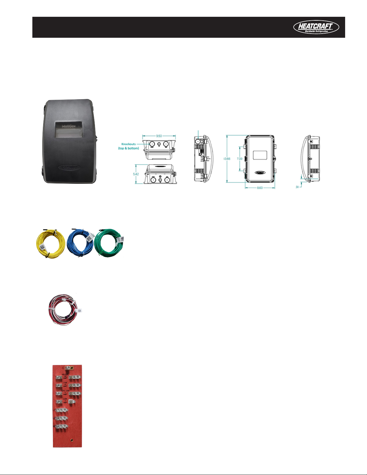
Terminal
Board
Pressure Transducer
Harness
Quick Start Guide & Manual
intelliGen Controller
Temperature
Sensor Brackets
Temperature Sensors
Pressure Transducer
& Accessories
intelliGen Field Mount (iFM) Kits
Wire Sheathing
5
• intelliGen Controller - Quantity of 1
Main control board and user interface board are pre-assembled in a IP65
rated housing.
For room temperature, suction temperature and coil temperature (25 feet
length)
• Temperature Sensors - Quantity of 3
For suction pressure transducer connection (25 feet length)
• Pressure Transducer Harness - Quantity of 1
For power, fan motors and defrost heater wire connections
• Terminal Board - Quantity of 1
Components Included in the Kit
intelliGen Field Mount (iFM) Kits
Knockouts
Knockouts (top & bottom)

6
Temperature Sensor Brackets & Accessories Bag
For mounting the room temperature sensor at the return air side of the unit
cooler.
• Room Temperature Sensor Bracket - Quantity of 1
For mounting the suction temperature sensor to the suction refrigeration line.
• Suction Temperature Sensor Tube - Quantity of 1
For mounting the coil temperature sensor to the coil.
• Coil Temperature Sensor Bracket - Quantity of 1
Two screws for the coil temperature sensor mounting bracket. Two screws for
the terminal board.
• Mounting Screws - Quantity of 4
Cable ties for securing the room temperature sensor to the mounting bracket.
• Cable Ties - Quantity of 2
intelliGen Field Mount (iFM) Kits
7
intelliGen Field Mount (iFM) Kits
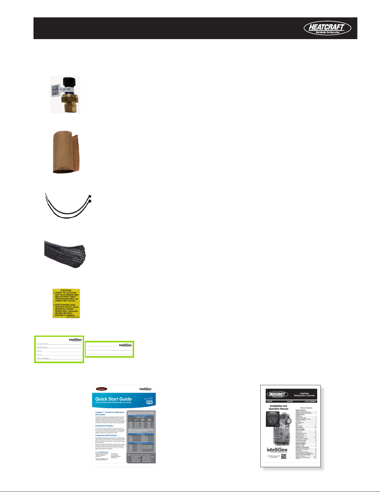
Pressure Transducer & Accessories Bag
Mount on the main suction line port to measure suction pressure.
• 300 PSI Pressure Transducer - Quantity of 1
Insulation tape for suction temperature sensor tube to prevent condensation
• Cork Tape Roll - Quantity of 1
Caution label for suction temperature sensor installation
• Caution Label - Quantity of 1
Instruction Manuals Bag
• intelliGen Installation
and Operation Manual
• iFM Kit Quick
Start Guide
Cable ties for securing suction temperature sensor inside the metal tube and
the suction line
• Cable Ties - Quantity of 2
Information labels to apply on user interface swinging panel
• Labels for User Interface Panel - Quantity of 1
Wrap wires inside the iFM kit housing for additional protection
• Wire Sheathing - Quantity of 4
8
Components NOT Included in the kit but are needed for
installation
These are system dependent components based on ap-
plication. Field installer to provide these components
separately based on the specific system requirement.
• 24VAC Control Power Transformer – quantity of 1
A 24VAC step down transformer from system voltages
(120VAC, 208-230VAC, 460VAC or 575VAC) is needed
to power the intelliGen control.
Note: For small unit coolers like Heatcraft's Low Profile
Unit Coolers with 460VAC or 575VAC system
voltages, external contactors are required to power
the motors and heaters due to limited cabinet space
to mount the components.
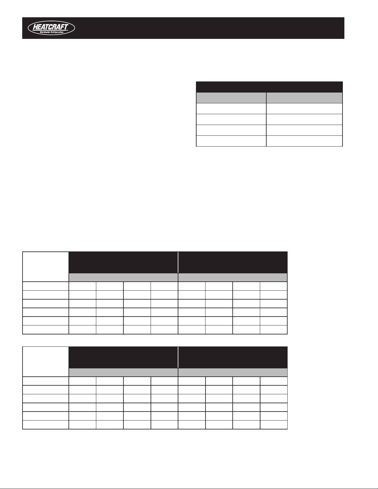
Heatcraft 24V AC Transformers
PART # Description
22529601 120/24VAC, 40VA
22529602 240/24VAC, 40VA
22529603 460/24VAC, 40VA
22529701 575/24VAC, 40VA
• Electronic Expansion Valve EXV -
Quantity of 1 (If use EXV is preferred)
These EXVs are available from Heatcraft. Field installer to select and provide one of these valves to match the system
capacity requirement. A valve cable with the length matches the conduit run is also required.
intelliGen Field Mount (iFM) Kits
intelliGen Field Mount (iFM) Kits
R-22
Evaporator Temperature (°F)
100 psi Pressure Drop
R-404A/R-507
Evaporator Temperature (°F)
100 psi Pressure Drop
+20 -20 +20 -20
PART NUMBER TONS BTUH TONS BTUH TONS BTUH TONS BTUH
29326101 0.44 5220 0.41 4920 0.73 8706 0.64 7692
29326201 4.25 51000 3.99 47900 3.11 37309 2.75 32966
29326401 7.52 90260 7.54 90480 4.66 55964 4.12 49449
29326501 15.14 181680 14.25 171000 10.89 130692 9.62 115480
29326601 22.18 266160 20.87 250440 16.08 192985 14.21 170521
R-407A
Evaporator Temperature (°F)
100 psi Pressure Drop
R-407C
Evaporator Temperature (°F)
100 psi Pressure Drop
+20 -20 +20 -20
PART NUMBER TONS BTUH TONS BTUH TONS BTUH TONS BTUH
29326101 0.99 11831 0.90 10808 1.07 12898 0.99 11863
29326201 4.23 50704 3.86 46320 4.61 55279 4.24 50839
29326401 6.34 76056 5.79 69481 6.91 82919 6.35 76258
29326501 14.80 177616 13.52 162259 16.14 193641 14.84 178088
29326601 21.86 262273 19.97 239598 23.83 285938 21.91 262970

9
These EXVs are available from Heatcraft. Field installer to select and provide one of these valves to match the system
capacity requirement. A valve cable with the length matches the conduit run is also required.
intelliGen Field Mount (iFM) Kits
intelliGen Field Mount (iFM) Kits
Sporlan SER and SERI Series of Electronic Expansion Valve Support
The Sporlan SER and SERI Series of electronic expansion valves are supported. This valve option is selectable in the
intelliGen Quick Start initial setup process. See Sporlan's website and document for SER and SERI Series valve sizes and
selection https://solutions.parker.com/sporlanvirtualengineer
R-449A
Evaporator Temperature (°F)
100 psi Pressure Drop
+20 -20
PART NUMBER TONS BTUH TONS BTUH
29326101 1.01 12125 0.92 11083
29326201 4.33 51965 3.96 47499
29326401 6.50 77947 5.94 71249
29326501 15.17 182030 13.87 166389
29326601 22.40 268793 20.47 245696
R-407F
Evaporator Temperature (°F)
100 psi Pressure Drop
R-448A
Evaporator Temperature (°F)
100 psi Pressure Drop
+20 -20 +20 -20
PART NUMBER TONS BTUH TONS BTUH TONS BTUH TONS BTUH
29326101 1.09 13067 1.01 12094 1.01 12128 0.92 11098
29326201 4.67 56001 4.32 51831 4.33 51977 3.96 47561
29326401 7.00 84001 6.48 77746 6.50 77966 5.95 71341
29326501 16.35 196168 15.13 181562 15.17 182075 13.88 166604
29326601 24.14 289669 22.34 268100 22.40 268859 20.50 246014
Cables for Carel EXV
PART NUMBER DESCRIPTION
22592201 10ft cable for Carel EXV
22592102 25ft cable for Carel EXV
22592103 40ft cable for Carel EXV

10
The field wire connections are to be provided by the field installer. A 25 feet long power harness with connectors and
terminals preassembled is available from Heatcraft for ease of installation. The part number is 22699902. It includes the
power wires listed below.
• 24VAC power wires for intelliGen control – two 18 AWG wire with ¼” quick connect terminal on one end and ¼”
piggyback quick connect terminal on the other end
• Fan motor wires – two 18 AWG wires with ¼” female quick connect terminals on both ends
• Defrost heater wires – two 14 AWG wires with fully insulated ¼” female quick connect terminals on both ends,
and two 18 AWG wires with fully insulated ¼” female quick connect terminals on both ends. (Wires need depend on
application.)
• Solenoid valve control wires – two 18 AWG wires with ¼” female quick connect terminals on one end and bare
wires on the other end. (Wires need depend on application.)
Heatcraft Power Harnesses
PART # Description
22699903 15ft harness for power, fan, defrost heater
22699902 25ft harness for power, fan, defrost heater
22699901 40ft harness for power, fan, defrost heater
intelliGen Field Mount (iFM) Kits
Conduit runs for field wires
Field wires between the intelliGen controller and the unit cooler should be in conduits and meet local building and
electric code requirements. Conduit fittings are also needed based on installation application. A site survey and instal-
lation planning is recommended to determine conduit lengths and the type of conduit fittings and quantity needed. It is
required to run power wires and low voltage (sensors and communication) wires in separate conduits.
Wire Protection
High voltage and low voltages wires inside the iFM kit requires additional insulation protection. Wire sheathing should
cover all wiring within the iFM enclosure. Sets of wire sheathing are provided with the iFM kit. High voltage wires may
share a sheath, and low voltage wires may share a sheath, but each group should be separately sheathed to maintain
separation.
Field Wire Connections
Power wires between system components and the intelliGen controller
Note:
For systems with defrost heater load higher than 30 Amp, external contactors are required to power the defrost
heaters. The defrost heaters relay on the intelliGen controller use as pilot relay for the external contactors.

11
intelliGen Field Mount (iFM) Kits
Unit Cooler Product Families Supported
The iFM Kit is designed to universal fit for Heatcraft’s Unit Coolers and other manufacturer’s Unit Coolers also.
Low Profile Unit Cooler
Center Mount Unit Cooler
Medium Profile Unit Cooler
Low Velocity Center Mount Unit Cooler
High Profile Large Unit Cooler

12
intelliGen Main Control Board (iRC) Layout
intelliGen Field Mount (iFM) Kits
Defrost
Heater
Relay
EXV
Grounded
Mounting
Screw
Evap
Fans
Relay
EXV
Capacitor
24V
Power
Supply
Central
Processing
Unit
USB Data
Port
Suction
Pressure
Aux
Temp Product Load
Switch
iRC-UI
Connection
Chasis
Ground
Grounded
Mounting
Screw
Condensing
Unit Connection
Door Switch
Evap
Communication
Connection
Grounded
Mounting
Screw
Coil
Temp
Suction
Temp
Box
Temp
Clock
Battery
Evap 2
Speed
Fans
Spare I/O
Alarm
Contacts
LLSV
Relay
13
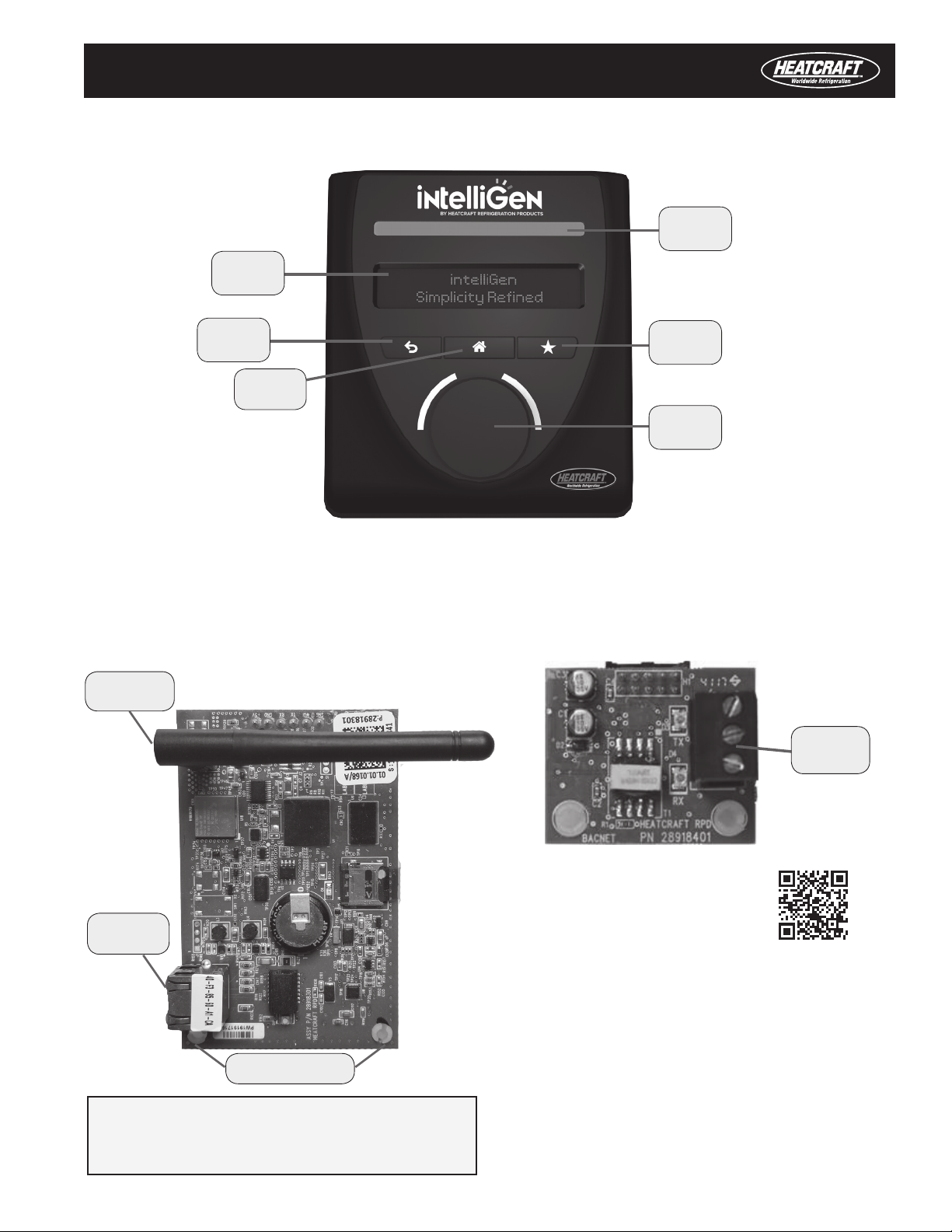
OLED
Display
Return
Button
Home
Button
Status
Light Bar
Favorites
Button
Control
Button
intelliGen User Interface (iRCUI) Layout
intelliGen Optional Remote Access Cards
intelliGen Field Mount (iFM) Kits
INTEGRATION CARD - iIC
MULTI-SYSTEM CONTROL CARD - MSC
WEBSERVER CARD - iWC
Wiring
Terminal
Long Name Abbrev. Name
Evap/Evaporator EV
Set-Point SP
Auxiliary AUX
Temperature/Temp TEMP
Calibration CALIB
Electronic Expansion Valve EXV
Condensing Unit CU
Compressor COMP
Connection CXN
Lead-Lag LL
LEGEND
NOTE: Refer to iWC & MSC Installation & Operation Manual
(H-IM-iWC/MSC for installation and maintenance instructions.
* MSC card comes with Wi-Fi Direct antenna and the iWC
webserver card does not come with Wi-Fi Direct antenna.
Scan QR code to view the manual or visit
www.intelliGencontrols.com/resources
Wi-Fi Direct
Antenna*
Ethernet
Connector
Screw Mount Holes
14
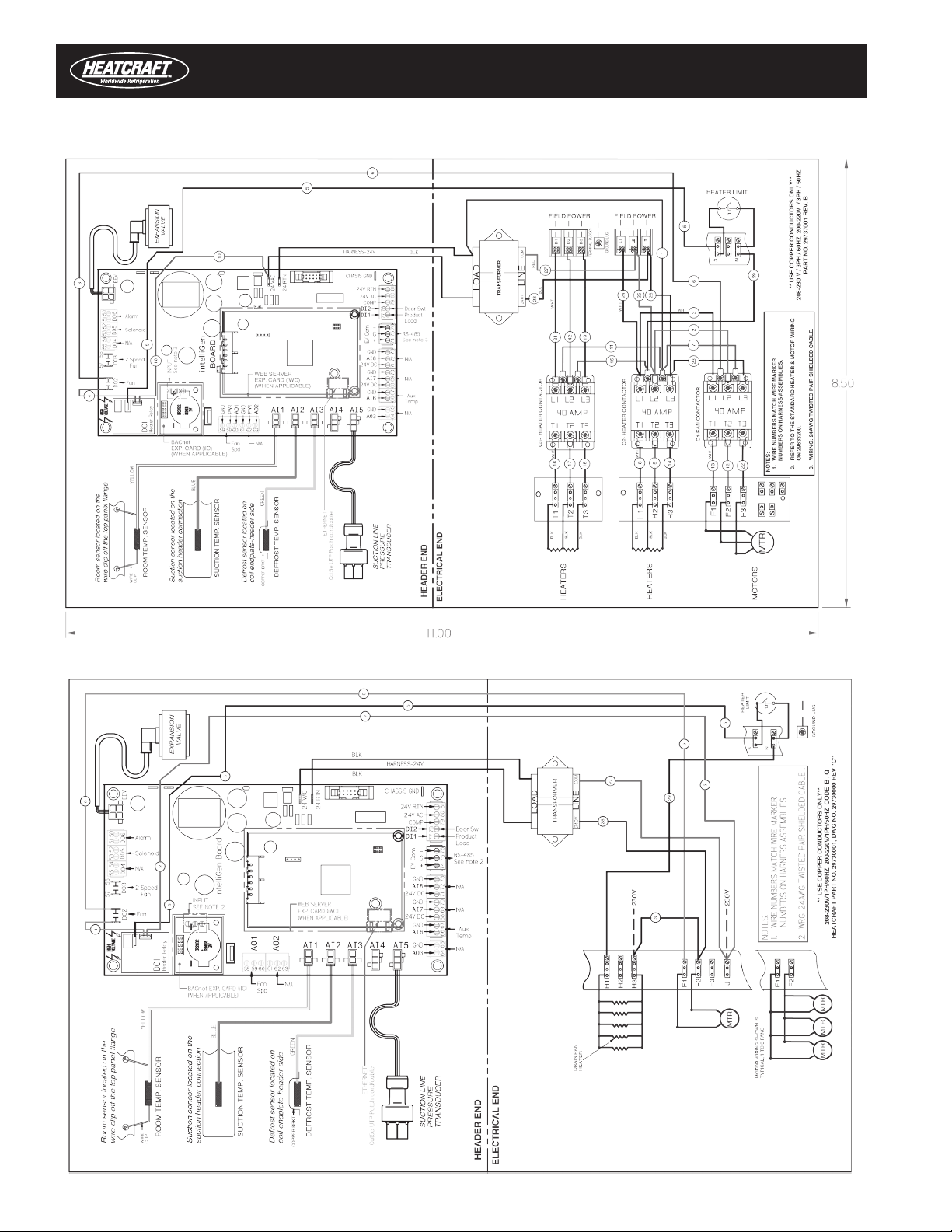
Typical Wiring Diagram For Applications Without Contactors
Typical Wiring Diagram For Applications With Contactors
iFM Kit Installation Section
15
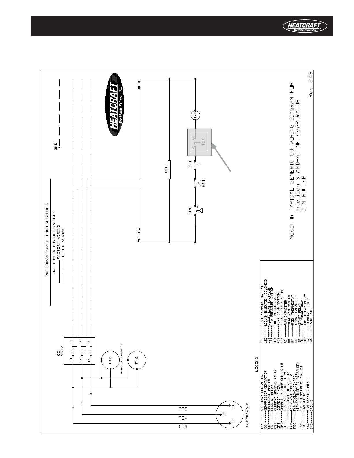
Typical Generic Condensing Unit Wiring Diagram
for intelliGen Stand-alone Evaporator Controller
iFM Kit Installation Section
TDR to be bypassed or
removed when installing
16
Remote Mount intelliGen Controller
1. Identify Remote Mount Location
The iFM kit designed to be remote mounted up to 40 feet
away from the unit cooler. The kit comes with 25 feet
long wire sensors. A 40 feet long wire sensors kit is
available separately. It can be mounted outside of a
walk-in cooler, near the entrance door.
a) Identify a flat surface to mount the iFM kit
b) Prepare the mounting location and mark screw
holes
Pro Tip: Use the iFM kit housing or the housing outline on the
Quick Start Guide and mark the four screw holes
2. Route Conduits and Wires to Unit Cooler
a) Determine length and conduit routing base on ap-
plication need
b) Determine the knockout on the iFM kit housing
to use for conduit and wires routing. (1-1/2” and
7/8” knockouts are available at the top, bottom
and the top left side of the housing.)
c) Determine the conduit fittings for connecting the
conduit to the iFM housing
d) Run wires through the conduits
e) Connect fittings to the conduits
Pro Tip: Use knockouts on the left side or the top side for power wires and use the knockouts on the bottom for sensors and
communication wires.
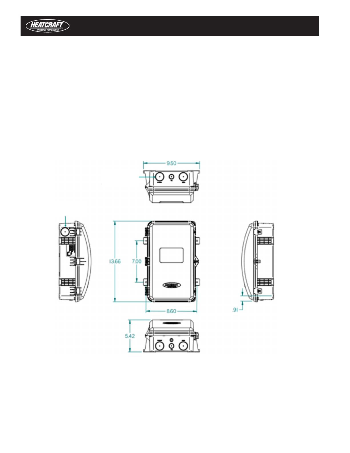
iFM Kit Assembly Dimensions (inch)
Knockouts
(top & bottom)
Knockouts
iFM Kit Installation Section

17
IntelliGen Board Layout
Remote Mount intelliGen Controller (Cont.)
3. Mount the iFM Kit
a) Mount the iFM kit housing to the marked screw hole
locations with #10, 1-1/4" long screws
b) Pull the wires through the knockouts on the iFM housing
c) Tighten the conduit fittings to the conduit and to the
iFM housing
4. Connect the wires to the intelliGen control board
a) Connect wires to the iRC main control board per the
connections layout below.
Defrost
Heater
Relay
EXV
Grounded
Mounting
Screw
Evap
Fans
Relay
EXV
Capacitor
24V
Power
Supply
Central
Processing
Unit
USB Data
Port
Suction
Pressure
Aux
Temp Product Load
Switch
iRC-UI
Connection
Chasis
Ground
Grounded
Mounting
Screw
Condensing
Unit Connection
Door Switch
Evap
Communication
Connection
Grounded
Mounting
Screw
Coil
Temp
Suction
Temp
Box
Temp
Clock
Battery
Evap 2
Speed
Fans
Spare I/O
Alarm
Contacts
LLSV
Relay
18
Components Installation in Unit Cooler
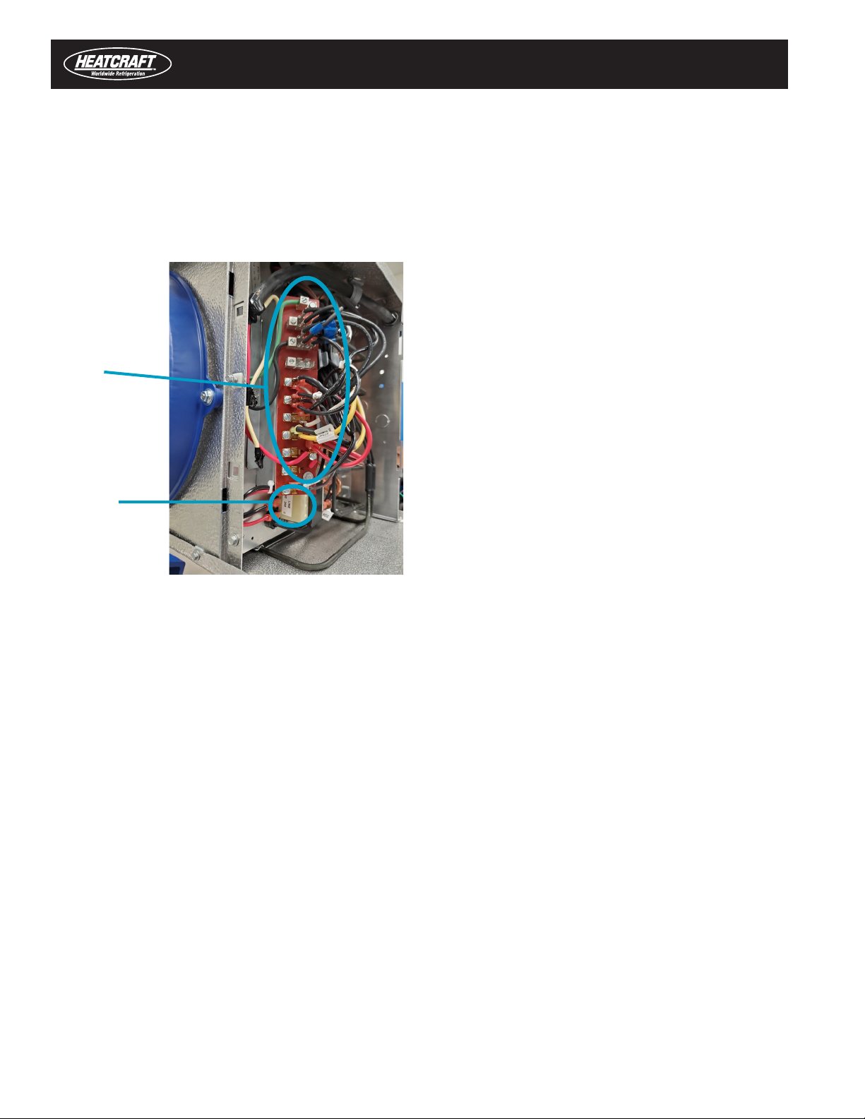
5. Power Transformer
a) Select a 24VAC transformer with the primary voltage
matches the system voltage
b) Connect the wires (transformer power, heater wires,
motor fan wires, solenoid valve wires) as needed per
the system requirement to the terminal board.
See wiring diagrams in the System Wiring Diagrams Section
on Pages 14 and 15.
b) Mount the transformer to the electrical end of the unit
cooler, see picture shown as example
6. Terminal Board
a) Mount the terminal board to the electrical end with the
screws provided
Pro Tip: Mount the new terminal board at the same loca-
tion of the existing terminal board for incoming power
New Unit Cooler Installation
STEP 5 & 6
Terminal Board
24VAC
Transformer
19
Components Installation in Unit Cooler (Cont.)
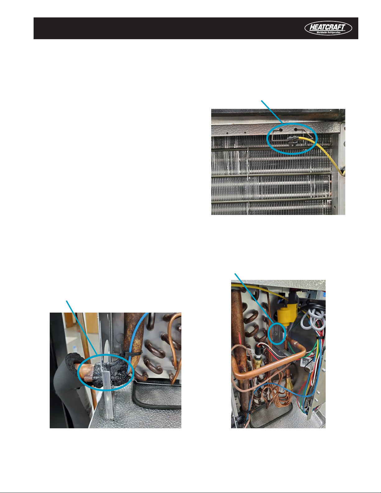
7. Temperature Sensors
a) Room Temperature Sensor
i. Drill two ¼” holes, 1-1/4" apart, on the return air area
of the unit cooler (typically at the back of the unit)
ii. Insert the Room Temperature Sensor Bracket into
the two drilled holes as shown in the picture
iii. Use cable ties to secure the Room Temperature
Sensor to the bracket as shown in the picture
b) Suction Temperature Sensor
i. Braze the metal Suction Temperature Sensor Tube
onto the suction line
ii. Insert the temperature sensor into the metal tube
iii. Wrap the temperature sensor and the metal tube
with cork tape
iv. Secure the temperature sensor with the cable ties
provided as shown in the picture
c) Coil Temperature Sensor
i. Attached the Coil Temperature Sensor onto the Coil
Temperature Sensor Bracket provided
ii. Screw tight the sensor bracket onto the coil end
plate with the self-drilling screws provided. See
picture as example
New Unit Cooler Installation
STEP 7b
STEP 7a
Room Temperature
Sensor
Suction Temperature
Sensor
STEP 7c
Coil Temperature
Sensor
20
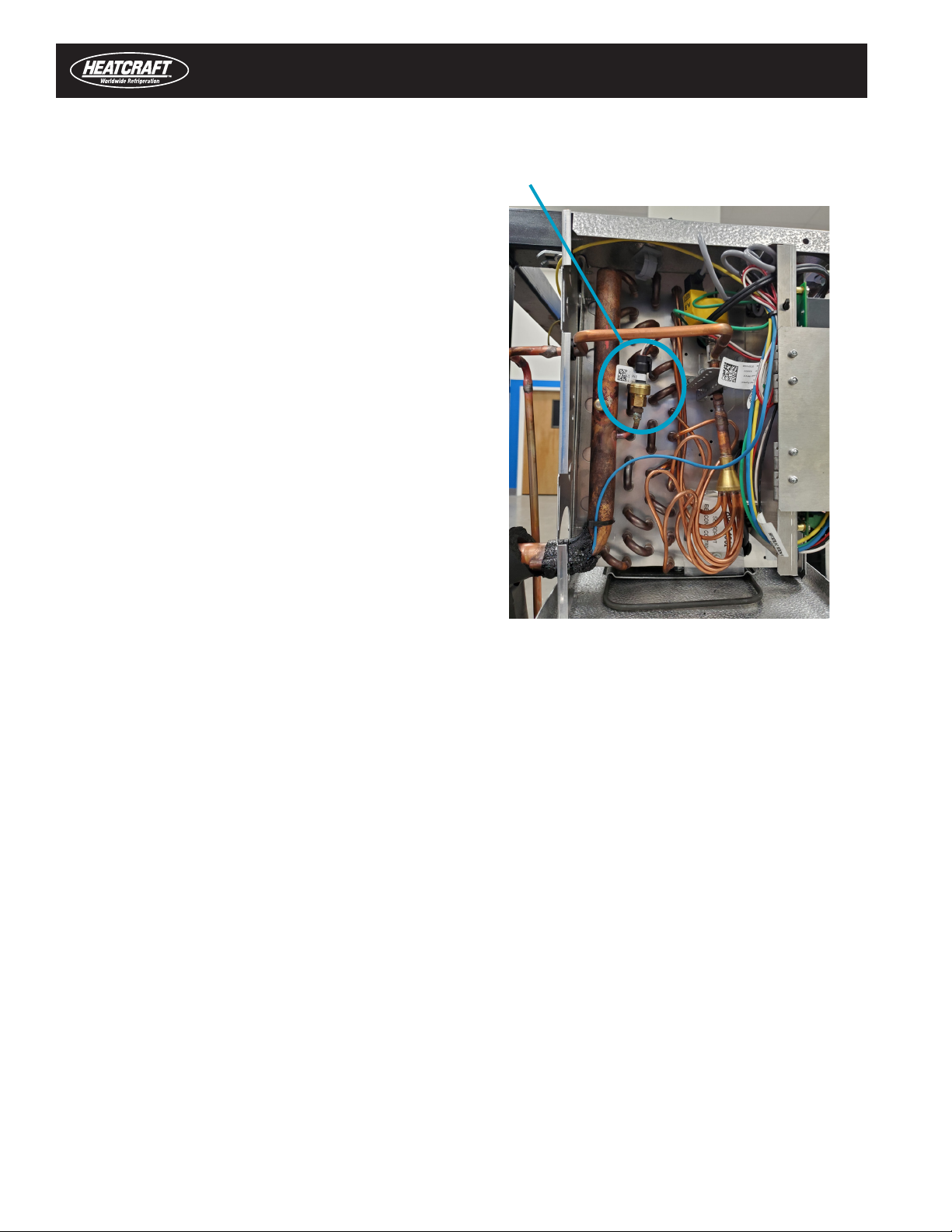
8. Pressure Transducer
a) Locate the Schrader valve on the suction line.
(Depends on system, a new Schrader valve may have
to be installed or brazed onto the suction line.)
b) Screw the pressure transducer onto the Schrader
valve.
Pro Tip: Use correct tools to prevent damage to the
Schrader valve and the copper pipe. Use 7/16” wrench
to hold steady of the Schrader valve at the bottom, then
tighten the pressure transducer at the top with a 5/8”
wrench
c) Plug in the pressure transducer harness and make
sure the harness clip securely latches over the
pressure transducer, see picture as example
New Unit Cooler Installation
STEP 8
Pressure Tranducer
Components Installation in Unit Cooler (Cont.)
Components Installation in Unit Cooler (Cont.)
This manual suits for next models
1
Table of contents
Other Heatcraft Controllers manuals


Popular Controllers manuals by other brands


dixell
dixell XM470K Installing and operating instructions

Onkyo
Onkyo SC886 - PR Preamplifier / Processor instruction manual

Wilo
Wilo fluidcontrol ek Assembly instructions

Milnor
Milnor MilTouch Operator's guide

Baldor
Baldor MicroFlex quick start guide

Full Gauge Controls
Full Gauge Controls TC-910R quick start guide


