VALVE ADDRESS:
#2
Options: Valve Address #1 (First Control Valve)
Valve Address #2 (Second Control Valve) (Default)
Valve Address #3 (Third Control Valve)
Valve Address #4 (Fourth Control Valve)
SYSTEM TYPE: 4
SINGLE UNIT
Options: System 4 (single unit)
System 5 (2-4 units) - Parallel Interlock
System 6 (2-4 units) - Parallel Series Regeneration
System 7 (2 units) - Alternating
System 9 (2-4 units) - Alternating
System 14 (2-4 units) - Demand Recall
Example:
System Type 4, Single Unit
Example:
Valve Address #2 (Second Control Valve) (Default)
SYSTEM SIZE:
2 VALVES
Options: 2 Valves in the System (Default)
3 Valves in the System
4 Valves in the System
Example:
2 Valves in the System (Default)
REGEN TYPE:
TIME CLK DELAYED
Options: Time Clock Delayed (System 4 Only) (Default)
Meter Immediate (All System Types)
Meter Delayed Fixed Reserve (Systems 4 & 6 Only)
Example:
Time Clock Delayed (Default)
VALVE TYPE:
STAGER-NOTCH CAM
Options: 2750
2850
2900
3150
3900
Stager - Notch Cam (Default)
Example:
Stager - Notch Cam (Default)
REMOTE SIGNAL
START:OFF
Options: 00:06:00 (Hours:Munutes:Seconds)
Range: 1 second to 99 minutes (1 hour, 39 minutes)
Example:
Off (Default)
DISPLAY FORMAT:
US-GALLONS
Options: U.S. - Gallons (Default)
EU-Metric - Liters (Metric)
Example:
U.S. Gallons (Default)
UNIT CAPACITY:
0300000 GRAINS
Options: Grains (in U.S. Format) (Default)
Grams (in Metric Format)
Example:
0300000 Grains (Default)
CAPACITY SAFETY
FACTOR: 00%
Range: 0 to 50%
Example:
00% (Default)
FEED WATER
HARDNESS: 15 GPG
Range: 1 to 199 Grains/Gallon (U.S. Format)
2 to 199 miligrams CaCOs/L (Metric Format)
Example:
15 GPG (U.S. Format) (Default)
SELECT LANGUAGE:
ENGLISH
Options: English
Espanol
Portugues
Deutsch
Francais
Example:
English
TRIP POINT 1:
000 gpm
Range: 2 to 4 Valves in the System
NOTE: This screen will not display for System Type 4.
NOTE: This screen will not display for System Type 4.
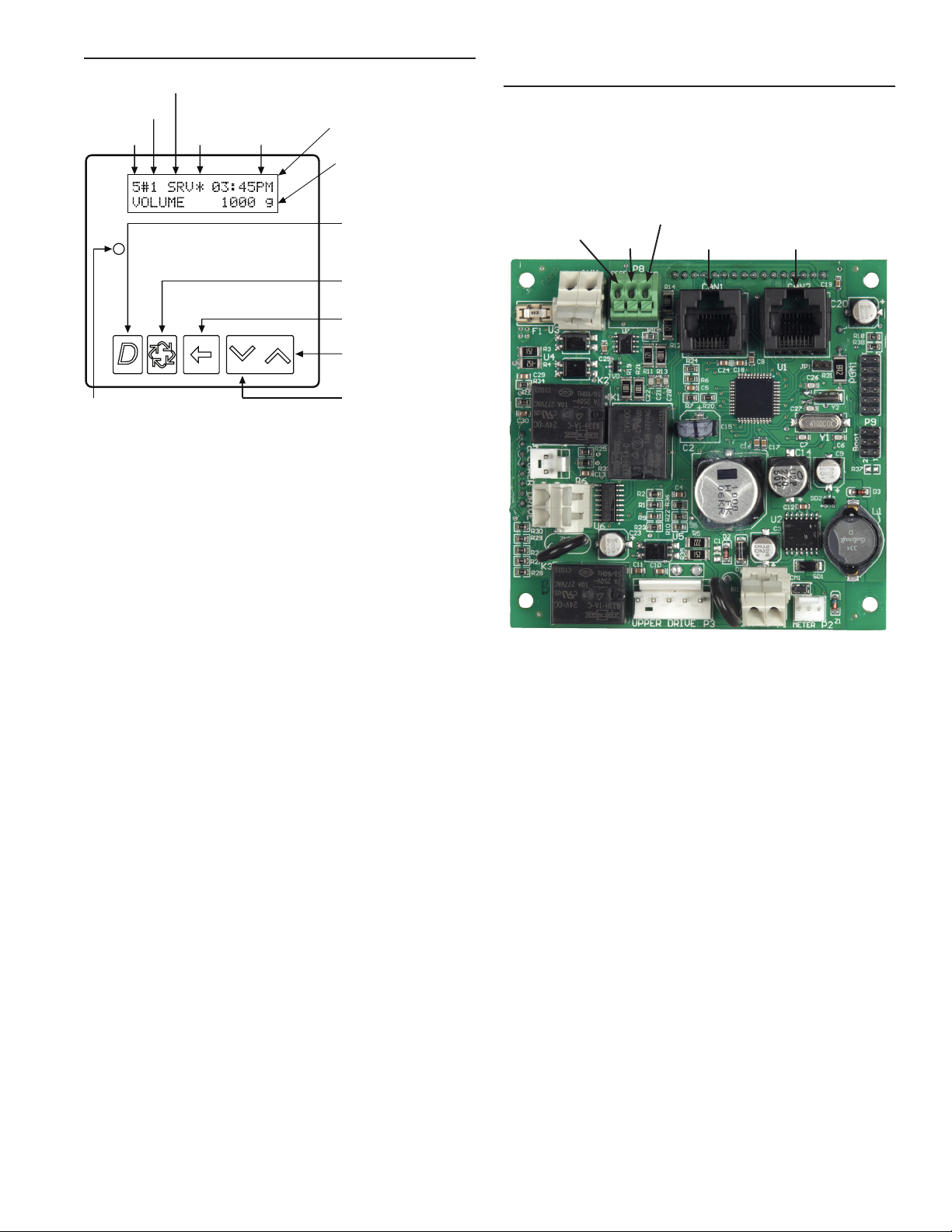
NOTE: In European Units - Liters (Metric) mode, the display will be in
24-hour time.
NOTE: In U.S. - Gallons mode, the display will be in 12-hour time.
NOTE: Use the Shift button to move to the left.
Range: 1 to 9,900,000 Grain Capacity in U.S. Format
1.0 to 190,000 grams CaCO3Capacity in Metric Format
NOTE: Use the Shift button to move to the left.
NOTE: Use the Shift button to move to the left.
NOTE: This screen will only display on the lead unit for System Types 6 & 7.
For all other System Types, it will display for all units.
NOTE: Display will only appear on the master timer and it must be
programmed as valve position #1. Use the Shift button to change each
decimal position.
NOTE: This screen will only display for System 14.
REGENERATION DAY
OVERRIDE:OFF
Example:
Off (Default for Meter)
On (Default for Time Clock)
REGENERATION DAY
OVERRIDE:01 DAYS
Options: Off (Default for Meter) or On (Default for Time Clock)
Example:
1 Day
Range: 1 to 99 Days
REGENERATION
TIME: 02:00AM
Example:
2:00 A.M. (Default)
Options: A.M. (U.S. Format)
HR (Metric Format)
NOTE: Regeneration time will not appear unless Regeneration Day Override
is on.
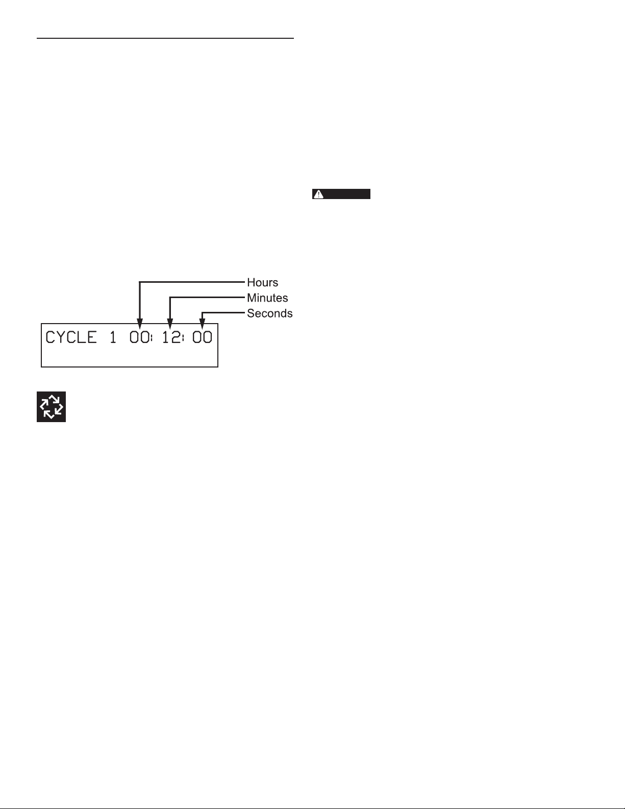
CYCLE 1 00:10:00 Example: Backwash
00:10:00 (Default 48-00 Stager & 51-09 Stager)
(Hours:Minutes:Seconds)
AUXILIARY RELAY:
DISABLED
Example:
Auxiliary Relay is Disabled
Options: Enabled
Disabled (Default)
AUX RELAY OUTPUT
START 1 00:00:00
Example:
Auxiliary Relay Output Start 1 at
0 hours, 0 minutes, & 0 seconds
Range: 00:00:00 to 18:00:00
NOTE: Only displayed if Auxiliary Relay is enabled in previous screen.
Auxiliary Relay will only display if Chemical Pump is OFF for System
Types 6 & 7.
AUX RELAY OUTPUT
END 1 00:00:00
Example:
Auxiliary Relay Output End 1 at
0 hours, 0 minutes, & 0 seconds
Range: 00:00:00 to 18:00:00
CHEMICAL PUMP:
DISABLED
Example:
Chemical Pump is Disabled
Options: Enabled
Disabled (Default)
NOTE: This screen will only display on the lead unit for System Types 6 & 7.
For all other System Types, it will display for all units.
CPO AUX RELAY
TIME: 00:00:00
Example:
Each time chemical pump relay is on, run for
30 seconds (00:00:30)
Range: 00:00:00 to 02:00:00
FLOW METER:
1.0 PADDLE
Example:
1.0 Paddle Flow Meter
Options: 1.0 Paddle (Fleck)
1.0 Turbine (Fleck)
1.5 Paddle (Fleck)
1.5 Turbine (Fleck)
2.0 Paddle (Fleck)
3.0 Paddle (Fleck)
Generic
NOTE: Default flow meter type is based on the valve type. This screen will
only display on the lead unit for System Types 6 & 7. All other system types
it will display for all units.
MAXIMUM FLOW
RATE: 0000 gpm
Example:
Maximum Flow Rate of 0 gpm
Range: 20 - 2000 gpm (U.S. Format)
20 - 2000 Lpm (Metric Format)
NOTE: Only displayed if “Generic” is chosen for the flow meter.
Range: 1 - 99 Gallons (U.S. Format)
0.1 - 09.9 L (Metric Format)
Pulses: 1 - 99
Options: Gallons (U.S. Format)
Liters (Metric Format)
ADD 01 GALLONS
EVERY 001 PULSES
Example:
Add 1 Gallon for Each Pulse in U.S. Format
NOTE: Only displayed if “Generic” is chosen for the flow meter.
PROGRAMMING UNIT
PLEASE WAIT...
Example:
Master Programming Mode is Exiting
CPO AUX RELAY
VOLUME: 000 9
Example:
Energize Chemical Pump relay every 50 gals (50)
Energize Chemical Pump relay every 200 L (200)
Range: 1 to 999 gallons in U.S. Format
1 to 9999 L in Metric Format
NOTE: Display will only appear on the master timer and it must be
programmed as valve position #1. System size must be 3 or 4 to appear. Use
the Shift button to move one space to the left.
NOTE: This screen will only display for System 14.
TRIP DELAY 2:
30 SECONDS
NOTE: Display will only appear on the master timer and it must be
programmed as valve position #1. System size must be 3 or 4 to appear. Use
the Shift button to move one space to the left.
NOTE: This screen will only display for System 14.
TRIP POINT 2:
gpm
NOTE: Display will only appear on the master timer and it must be
programmed as valve position #1. System size must be 4 to appear. Use the
Shift button to move one space to the left.
NOTE: This screen will only display for System 14.
TRIP POINT 3:
gpm
NOTE: Display will only appear on the master timer and it must be
programmed as valve position #1. System size must be 4 to appear. Use the
Shift button to move one space to the left.
NOTE: This screen will only display for System 14.
TRIP DELAY 3:
30 SECONDS
NOTE: This display will not be viewed in System 14.
NOTE: Display will only appear on the master timer and it must be
programmed as valve position #1. Use the Shift button to move one space
to the left.
TRIP DELAY 1:
30 SECONDS
NOTE: This screen will only display for System 14.
CYCLE 2 01:00:00 Example: Brine
01:00:00 (Default 48-00 Stager & 51-09 Stager)
(Hours:Minutes:Seconds)
Options: 01:00:00 for Conditioner for the 48-00 Stager & 51-09 Stager
(Default)
00:00:00 for Filter for the 48-00 Stager
CYCLE 3 00:10:00 Example: Fast Rinse
00:10:00 (Default 48-00 Stager & 51-09 Stager)
(Hours:Minutes:Seconds)
CYCLE 4 OFF Example:
Off (Default 48-00 Stager)
CYCLE 4 00:12:00 Example: Refill
00:12:00 (Default 51-09 Stager)
(Hours:Minutes:Seconds)
NOTE: This screen will only display when cycle 4 is not OFF.
CYCLE 5 OFF Example:
Off (Default 51-09 Stager)
1 to 997 gpm
1 to 3997 Lpm
2 to 998 gpm
1 to 3997 Lpm
3 to 999 gpm
1 to 3997 Lpm
VALVE ADDRESS:
#2
Options: Valve Address #1 (First Control Valve)
Valve Address #2 (Second Control Valve) (Default)
Valve Address #3 (Third Control Valve)
Valve Address #4 (Fourth Control Valve)
SYSTEM TYPE: 4
SINGLE UNIT
Options: System 4 (single unit)
System 5 (2-4 units) - Parallel Interlock
System 6 (2-4 units) - Parallel Series Regeneration
System 7 (2 units) - Alternating
System 9 (2-4 units) - Alternating
System 14 (2-4 units) - Demand Recall
Example:
System Type 4, Single Unit
Example:
Valve Address #2 (Second Control Valve) (Default)
SYSTEM SIZE:
2 VALVES
Options: 2 Valves in the System (Default)
3 Valves in the System
4 Valves in the System
Example:
2 Valves in the System (Default)
REGEN TYPE:
TIME CLK DELAYED
Options: Time Clock Delayed (System 4 Only) (Default)
Meter Immediate (All System Types)
Meter Delayed Fixed Reserve (Systems 4 & 6 Only)
Example:
Time Clock Delayed (Default)
VALVE TYPE:
STAGER-NOTCH CAM
Options: 2750
2850
2900
3150
3900
Stager - Notch Cam (Default)
Example:
Stager - Notch Cam (Default)
REMOTE SIGNAL
START:OFF
Options: 00:06:00 (Hours:Munutes:Seconds)
Range: 1 second to 99 minutes (1 hour, 39 minutes)
Example:
Off (Default)
DISPLAY FORMAT:
US-GALLONS
Options: U.S. - Gallons (Default)
EU-Metric - Liters (Metric)
Example:
U.S. Gallons (Default)
UNIT CAPACITY:
0300000 GRAINS
Options: Grains (in U.S. Format) (Default)
Grams (in Metric Format)
Example:
0300000 Grains (Default)
CAPACITY SAFETY
FACTOR: 00%
Range: 0 to 50%
Example:
00% (Default)
FEED WATER
HARDNESS: 15 GPG
Range: 1 to 199 Grains/Gallon (U.S. Format)
2 to 199 miligrams CaCOs/L (Metric Format)
Example:
15 GPG (U.S. Format) (Default)
SELECT LANGUAGE:
ENGLISH
Options: English
Espanol
Portugues
Deutsch
Francais
Example:
English
Range: 2 to 4 Valves in the System
NOTE: This screen will not display for System Type 4.
NOTE: This screen will not display for System Type 4.
NOTE: In European Units - Liters (Metric) mode, the display will be in
24-hour time.
NOTE: In U.S. - Gallons mode, the display will be in 12-hour time.
NOTE: Use the Shift button to move to the left.
Range: 1 to 9,900,000 Grain Capacity in U.S. Format
1.0 to 190,000 grams CaCO3Capacity in Metric Format
NOTE: Use the Shift button to move to the left.
NOTE: Use the Shift button to move to the left.
NOTE: This screen will only display on the lead unit for System Types 6 & 7.
For all other System Types, it will display for all units.
NOTE: Display will only appear on the master timer and it must be
programmed as valve position #1. Use the Shift button to change each
decimal position.
NOTE: This screen will only display for System 14.
REGENERATION DAY
OVERRIDE:OFF
Example:
Off (Default for Meter)
On (Default for Time Clock)
REGENERATION DAY
OVERRIDE:01 DAYS
Options: Off (Default for Meter) or On (Default for Time Clock)
Example:
1 Day
Range: 1 to 99 Days
REGENERATION
TIME: 02:00AM
Example:
2:00 A.M. (Default)
Options: A.M. (U.S. Format)
HR (Metric Format)
NOTE: Regeneration time will not appear unless Regeneration Day Override
is on.
CYCLE 1 00:10:00 Example: Backwash
00:10:00 (Default 48-00 Stager & 51-09 Stager)
(Hours:Minutes:Seconds)
AUXILIARY RELAY:
DISABLED
Example:
Auxiliary Relay is Disabled
Options: Enabled
Disabled (Default)
AUX RELAY OUTPUT
START 1 00:00:00
Example:
Auxiliary Relay Output Start 1 at
0 hours, 0 minutes, & 0 seconds
Range: 00:00:00 to 18:00:00
NOTE: Only displayed if Auxiliary Relay is enabled in previous screen.
Auxiliary Relay will only display if Chemical Pump is OFF for System
Types 6 & 7.
AUX RELAY OUTPUT
END 1 00:00:00
Example:
Auxiliary Relay Output End 1 at
0 hours, 0 minutes, & 0 seconds
Range: 00:00:00 to 18:00:00
CHEMICAL PUMP:
DISABLED
Example:
Chemical Pump is Disabled
Options: Enabled
Disabled (Default)
NOTE: This screen will only display on the lead unit for System Types 6 & 7.
For all other System Types, it will display for all units.
CPO AUX RELAY
TIME: 00:00:00
Example:
Each time chemical pump relay is on, run for
30 seconds (00:00:30)
Range: 00:00:00 to 02:00:00
FLOW METER:
1.0 PADDLE
Example:
1.0 Paddle Flow Meter
Options: 1.0 Paddle (Fleck)
1.0 Turbine (Fleck)
1.5 Paddle (Fleck)
1.5 Turbine (Fleck)
2.0 Paddle (Fleck)
3.0 Paddle (Fleck)
Generic
NOTE: Default flow meter type is based on the valve type. This screen will
only display on the lead unit for System Types 6 & 7. All other system types
it will display for all units.
MAXIMUM FLOW
RATE: 0000 gpm
Example:
Maximum Flow Rate of 0 gpm
Range: 20 - 2000 gpm (U.S. Format)
20 - 2000 Lpm (Metric Format)
NOTE: Only displayed if “Generic” is chosen for the flow meter.
Range: 1 - 99 Gallons (U.S. Format)
0.1 - 09.9 L (Metric Format)
Pulses: 1 - 99
Options: Gallons (U.S. Format)
Liters (Metric Format)
ADD 01 GALLONS
EVERY 001 PULSES
Example:
Add 1 Gallon for Each Pulse in U.S. Format
NOTE: Only displayed if “Generic” is chosen for the flow meter.
PROGRAMMING UNIT
PLEASE WAIT...
Example:
Master Programming Mode is Exiting
CPO AUX RELAY
VOLUME: 000 9
Example:
Energize Chemical Pump relay every 50 gals (50)
Energize Chemical Pump relay every 200 L (200)
Range: 1 to 999 gallons in U.S. Format
1 to 9999 L in Metric Format
NOTE: Display will only appear on the master timer and it must be
programmed as valve position #1. System size must be 3 or 4 to appear. Use
the Shift button to move one space to the left.
NOTE: This screen will only display for System 14.
TRIP DELAY 2:
30 SECONDS
NOTE: Display will only appear on the master timer and it must be
programmed as valve position #1. System size must be 3 or 4 to appear. Use
the Shift button to move one space to the left.
NOTE: This screen will only display for System 14.
TRIP POINT 2:
gpm
NOTE: Display will only appear on the master timer and it must be
programmed as valve position #1. System size must be 4 to appear. Use the
Shift button to move one space to the left.
NOTE: This screen will only display for System 14.
TRIP POINT 3:
gpm
NOTE: Display will only appear on the master timer and it must be
programmed as valve position #1. System size must be 4 to appear. Use the
Shift button to move one space to the left.
NOTE: This screen will only display for System 14.
TRIP DELAY 3:
30 SECONDS
NOTE: This display will not be viewed in System 14.
NOTE: Display will only appear on the master timer and it must be
programmed as valve position #1. Use the Shift button to move one space
to the left.
TRIP DELAY 1:
30 SECONDS
NOTE: This screen will only display for System 14.
CYCLE 2 01:00:00 Example: Brine
01:00:00 (Default 48-00 Stager & 51-09 Stager)
(Hours:Minutes:Seconds)
Options: 01:00:00 for Conditioner for the 48-00 Stager & 51-09 Stager
(Default)
00:00:00 for Filter for the 48-00 Stager
CYCLE 3 00:10:00 Example: Fast Rinse
00:10:00 (Default 48-00 Stager & 51-09 Stager)
(Hours:Minutes:Seconds)
CYCLE 4 OFF Example:
Off (Default 48-00 Stager)
CYCLE 4 00:12:00 Example: Refill
00:12:00 (Default 51-09 Stager)
(Hours:Minutes:Seconds)
NOTE: This screen will only display when cycle 4 is not OFF.
CYCLE 5 OFF Example:
Off (Default 51-09 Stager)
1 to 997 gpm
1 to 3997 Lpm
2 to 998 gpm
1 to 3997 Lpm
3 to 999 gpm
1 to 3997 Lpm
MASTER PROGRAMMING MODE FLOW
CHART
Before entering Master Programming, please
contact your local professional water dealer.
WhentheMasterProgrammingModeisentered,parameters
canbesettomakethetimer(s)functionasneeded.
NOTE: Depending on current option settings, some
displays cannot be viewed or set.
Entering Master Programming Mode
1. PressandholdtheShiftandUpbuttonsfor5seconds.
OR
2. Setthetimeofdaydisplayto12:01PMor12:01HR.Press
andholdUporDownbuttonstosetthetime.Thenpress
theUpandDownbuttonsatthesametimefor5seconds.
Exiting Master Programming Mode
1. PresstheExtraCyclebuttononceperdisplayuntilall
areviewed.MasterProgrammingModeisexitedandthe
normaldisplayscreenappears.
2. ToexittheMasterProgrammingModewithoutsaving
changes,presstheDiagnosticbutton.
NOTE: If no keypad activity is made for 5 minutes while
in the Master Programming Mode, or if there is a
power failure, no changes will be saved, and the
unit will go back to the main display screen.
Resets
Soft Reset: PressandholdtheUpandDownbuttonsfor25
secondsuntil12:00PM(or12:00HR)appears.Thisresetsall
parametersexceptfortheowmetertotalizervolume.
Master Reset: HoldtheExtraCyclebuttonwhilepoweringup
theunit.Thisresetsalloftheparametersintheunit.Check
andverifythechoicesselectedinMasterProgrammingMode.
NXTStagerControllerFE11•7