HEATEC VEGA PULS 63.UX User instructions

Figure 3. PLICSCOM indicating and adjustment module.
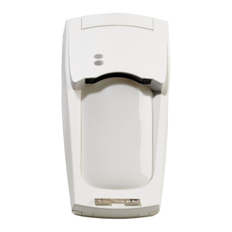
Figure 2. VEGA PULS 63.UX radar sensor.
Figure 1. Heatec vertical asphalt tanks.
Setting up Vega radar sensors
for Heatec vertical asphalt tanks
This document provides information for setting
up Vega radar sensors installed on Heatec tanks
that store liquid asphalt (Figure 1). It applies
to VEGA PULS 63.UX (Figure 2) and PULS
65.UX sensors with Indicating and Adjustment
Module PLICSCOM (Figure 3). It applies to
Heatec vertical tanks with capacities ranging from
10,000 to 35,000 gallons. The sensors are optional
equipment for Heatec tanks.
The sensors indicate levels of asphalt in the tanks.
Levels are shown in feet, measured from the
bottom of the tank.
This document is furnished with Heatec vertical
tanks equipped with the sensor. Applicable
operating instructions, published by Vega are also
furnished. Both documents are needed to set up the
radar sensors for Heatec tanks.
The sensors require a preliminary setup and a final
setup. The preliminary setup is normally done at
the Heatec factory. The final setup should be done
in the field after the tank is operational. If a new
sensor is installed in the field, and the preliminary
setup was not done at Heatec, it must be done
before final setup can be done.
Publication No. 5-04-116 Revised 6-17-10
HEATEC TEC-NOTE

Page 2
NOTICE
This document supplements the Vega manual
and should always be used along with the Vega
manual. Be sure to read all appropriate warnings
and precautions in the Vega manual before
doing any work on Vega sensors. The following
statement appears in the Vega manual and should
be followed:
Authorized personnel
All operations described in this operating
instructions manual must be carried out
only by trained and authorized specialist
personnel. For safety and warranty reasons,
any internal work on the instruments must
be carried out only by VEGA personnel.
PRELIMINARY SETUP
The preliminary setup can be made either before
the sensor is installed on the tank or after it is
installed. Use the buttons on the PLICSCOM
module (Figure 3) to make the settings. Set the
sensor according to the settings shown in Figure
4. Do not change any settings other than the ones
shown in Figure 4. These are the settings we use
for preliminary setup of the sensors at the Heatec
factory. They are the only settings we change from
the original Vega factory settings.
HINT: Before trying to set the PLICSCOM
module, be sure to get familiar with its four
keys (refer to applicable instructions in the Vega
manual). When navigating the menu on the module
of the sensor, make sure the menu numbers
(which appear in the upper right-hand corner of
the display) match the menu numbers shown in
Figure 4. The menu terminology shown in Figure
4 should match the menu terminology that appears
on the PLICSCOM module.
NOTE: Please disregard any minor differences
in terminology shown in Vega manuals and the
terminology that appears in the display of the
PLICSCOM module. These differences should not
affect your setup procedure.
FINAL SETUP
Final setup of the sensor can only be done after the
sensor is installed in the tank. During final setup
the sensor creates an electronic profile of the inside
of the tank. It senses obstructions, such as ladders,
mixing blades, etc. It stores the profile in memory
and uses it to eliminate false echoes from those
components. This procedure is known as False
echo memory.
We normally run the false echo memory procedure
on empty tanks equipped with sensors at the
Heatec factory. At that time the tanks are new and
have never been filled with asphalt. The profile
we create should enable the sensor to provide
fairly stable and accurate indications of level.
However, the sensor will provide greater stability
and accuracy if the procedure is repeated after
the inside of the tank is coated with asphalt. The
sensor can be set to update the profile that was
originally made at Heatec.
We recommend that you update the profile after
the tank has been used for a while. Do this when
the asphalt level is barely above the heating coils
or at the lowest level before you would normally
refill the tank. If the tank has a mixer, make sure it
is running while performing this procedure.
Basic instructions for creating false echo profiles
are in the Vega manual.
Here’s how to build an accurate profile: Set the
sensor module to menu 4.1 False echo memory. You
will see the word: Change? Press the OK button
and you will be presented with three choices:
Delete, Update, Create new. Be sure to choose update.
Otherwise, you will delete the profile that was
created at Heatec.
NOTE: While you are running the false echo
memory procedure you will be prompted to
enter the distance from the sensor to the surface
of the asphalt. So, be prepared to make actual
measurements through the manway in the top
of the tank. You will need to measure from the
surface of the asphalt to the mounting flange of the
sensor.
TROUBLESHOOTING
The sensor may show erroneous readings if its
antenna becomes contaminated with asphalt
residues. If this happens you must remove the
sensor unit and clean the antenna using a solvent
Publication No. 5-04-116

Figure 4. Settings for VEGA PULS 63 and PULS 65
with Indicating and Adjustment Module PLICSCOM
SENSOR
MENU
HEATEC VERTICAL TANKS
TAV-10 TAV-15 TAV-20 TAV-25 TAV-30 TAV-35
1 Basic Adjustment
1.1 Min. adjustment 0.00%
16’ 06” 2/16
0.00%
24’ 06” 2/16
0.00%
30’ 06” 2/16
0.00%
38’ 06” 2/16
0.00%
44’ 06” 2/16
0.00%
50’ 06” 2/16
1.2 Max. adjustment 100.00%
2’ 00” 2/16
100.00%
2’ 00” 2/16
100.00%
2’ 00” 2/16
100.00%
2’ 00” 2/16
100.00%
2’ 00” 2/16
100.00%
2’ 00” 2/16
1.3 Medium Unknown Unknown Unknown Unknown Unknown Unknown
1.4 Vessel type Stirred Vessel Stirred Vessel Stirred Vessel Stirred Vessel Stirred Vessel Stirred Vessel
1.5 Damping 0 s 0 s 0 s 0 s 0 s 0 s
1.6 Linearization
curve Linear Linear Linear Linear Linear Linear
1.7 Sensor-tag Sensor Sensor Sensor Sensor Sensor Sensor
2 Display
2.1 Display value Height Height Height Height Height Height
4 Service
4.3 Current output
Output mode
Failure mode
Min. current
4-20 mA
< 3,6 mA
3,8 mA
4-20 mA
< 3,6 mA
3,8 mA
4-20 mA
< 3,6 mA
3,8 mA
4-20 mA
< 3,6 mA
3,8 mA
4-20 mA
< 3,6 mA
3,8 mA
4-20 mA
< 3,6 mA
3,8 mA
4.6 Select ft (d) ft (d) ft (d) ft (d) ft (d) ft (d)
Page 3
that will dissolve asphalt. Before removing the
sensor be absolutely sure to mark its position so it
can be reinstalled in the same position. Otherwise,
all of the false echo memory information will be
useless and the sensor will not function properly.
Note: The sensor has a small hole drilled in the
side of its stainless steel body. This hole should
always point towards the center of the tank.
REVISIONS TO SETTINGS IN FIGURE 4
Over the years we have revised the settings shown
in Figure 4 because we have found that some work
better than others for asphalt storage tanks. The
settings we now recommend are shown in Figure
4. If your unit is new, make sure its settings match
those shown in Figure 4. However, if you have an
older unit that has been in service for quite a while
and it is working well, there is no need to change
its settings.
EFFECT ON CONTROLLERS
The settings shown in Figure 4 are coordinated
with settings of the controller used with the radar
unit. Be sure to check controller settings to make
sure they agree with radar unit settings in Figure
4. Otherwise, level indications will be erroneous
and shutoff control will not work properly!
See Heatec Tec-Note 6-10-236 Setting Yokogawa
UT150 controller used with Heatec vertical
asphalt tanks or Tec-Note 5-04-120 Setting
Publication No. 5-04-116

Page 4
Figure 5. High-level proximity switch and float pipe protruding
through sleeve in top of tank.
Honeywell controller used with Heatec vertical
asphalt tanks.
SPECIAL SETTINGS
All of the current VEGA radar units used on
Heatec AC tanks have special factory settings.
These settings can only be made using a computer
loaded with special Vega software and a special
connect cable. These settings cannot be made
using the keys on the PLICSCOM module.
One of the special settings is known as SECURITY.
Prior to September 2004 it was set to ON. The
advantage of having this setting turned on, is that
the unit provides better control of tank overflow.
However, having this setting activated can
create a problem in an environment where
there is condensation of moisture and vapors. If
condensation accumulates on the radar antenna
it can keep the radar unit from working properly.
This may occur inside an asphalt tank.
Accordingly, radar units used on Heatec AC tanks
starting September 2004 have the SECURITY
setting set to OFF. This should eliminate possible
problems due to condensation.
If your Heatec tank uses a radar unit that has
settings made prior to September 2004 and you
think you may be experiencing problems due to
condensation, please contact the Heatec service
department.
NOTE: The Vega software is designed primarily
for use by original equipment manufacturers
(OEMs) such as Heatec. It is not recommended for
end users.
OVERFLOW PROTECTION
Turning off the SECURITY setting does not leave
the radar without overflow protection. However,
it could make the radar overflow control more
susceptible to problems if the radar antenna is
accidentally immersed in asphalt.
In any case, a backup system will prevent overflow
if the radar is not working properly. The backup
system consists of a proximity switch activated by
a float (Figure. 5 and 6). The proximity switch
will shut off the unloading pump when filling the
tank and the float activates the proximity switch.
An indicator light labeled HIGH ASPHALT FLOAT
LEVEL (at the unloading pump controls) comes
on when the proximity switch has been activated.
For more information on shutoff controls please
refer to Heatec Tec-Note 9-04-147 Heatec asphalt
tanks—maintenance.
In normal operation the radar shuts off the
unloading pump before the proximity switch is
activated. Thus, if the proximity switch shuts off
the unloading pump it means that the radar is not
working properly.
So every time you fill the tank pay special
attention to whether the indicator light for
high float level comes on. If it does come on,
this indicates that the radar failed to shutoff the
unloading pump and the shutoff was achieved only
by the backup system.
Publication No. 5-04-116

Page 5
Figure 6. Float for high-level proximity switch.
© 2010 Heatec, Inc.
Heatec, Inc. 5200 Wilson Road Chattanooga, Tennessee 37410 www.heatec.com (423) 821-5200 (800) 235-5200 Fax (423) 821-7673
If the radar fails to shut off the unloading pump
the most likely cause is that the radar antenna was
accidentally immersed in asphalt. This should not
happen in normal operation. Cleaning the radar
antenna should restore the radar unit to normal
operation.
In the unlikely event that both the radar and
proximity switch fails to shut off the unloading
pump, the asphalt level will reach the top of the
vent/overflow pipe inside the tank. It will then
spill into the pipe, which will carry it out of the
tank onto the ground at the bottom of the tank.
Moreover, if an overflow occurs, you can be sure
that the asphalt level was high enough to immerse
the radar antenna.
RESERVED SPACE
Some space in the top of the tank is reserved to
allow for expansion of asphalt and for overflow
control when filling the tank. So you should not
expect to fill the entire space inside a tank with
asphalt. Your volume of asphalt will always be
somewhat less than the volume of the tank.
The settings shown in Figure 4 cause the radar
to shut off the unloading pump when the liquid
reaches a level approximately 18-5/8 inches below
the bottom surface of the upper bulkhead inside
the tank. At this level the asphalt will be 38-1/8
inches from the bottom surface of the flange of the
radar unit. This is the surface from which all radar
measurements are made.
The proximity switch and float system is set up
to shut off the unloading pump when the level of
asphalt is approximately 7-1/8 inches from the
bottom surface of the upper bulkhead
OLDER TANKS
Certain dimensions on vertical tanks manufactured
prior to 2001 may differ from those on tanks
manufactured after that year. If a radar unit is
being retrofitted to a vertical tank manufactured
prior to 2001 you may need to use different radar
settings than those shown in Figure 4. Otherwise
the level indications may be incorrect. Please
contact Heatec service department for help.
TECHNICAL SUPPORT
For questions about sensor settings for Heatec
tanks, please contact the Heatec service dept,
phone 423-821-5200. Please have the model of
your sensor. If your sensor was installed at the
Heatec factory, please have the Heatec job number.
If you need a manual for the VEGA PLICSCOM
sensor you can download one from heatec.com/
literature/Tec-Notes/acTank_pubs.htm.
For problems with the sensor, please contact
Ohmart/Vega Customer Support at 1-800-367-
5383 or 1-800-543-8668. Please have sensor
model. Before calling, please verify that your
settings match those shown in Figure 4.
Publication No. 5-04-116
This manual suits for next models
1
Table of contents


