GF Signet 8850-3 User manual

1. Location of Fitting
Recommended sensor upstream/downstream
mounting requirements
+GF+SIGNET 515/3-8510-XX Rotor-X Paddlewheel Flow Sensor
+45°
-45°
0°
Process
Pipe
2. Sensor Mounting Position
• Horizontal pipe runs: Mount sensor in
the upright (0°) position for best overall
performance. Mount at a maximum of
45°when air bubbles are present. Do not
mount on the bottom of the pipe when
sediments are present.
• Vertical pipe runs: Sensor must be
mounted in lines with UPWARD flow only.
Blk
F-
Red
F+
Shld
black (AC signal out)
red (AC signal out)
silver (shield)
515/3-8510-XX Sensors
Instrument
Technical Notes
• Use 2-conductor shielded cable for cable extensions up to 60 m (200 ft).
• Cable shield must be maintained through cable splice.
• Refer to your instrument manual for specific wiring details.
Iron
strap-on
saddles
Type Description
• 2 to 4 in., cut 1-7/16 in. hole in pipe
• Over 4 in., cut 2-1/4 in. hole in pipe
• Special order over 12 in.
• 0.5 to 4 in. versions
• PVC or CPVC
• Mounts via glue-on fittings
Plastic tees
PVC glue-on
saddles
(O-ring not
required)
• 2 to 4 in., cut 1-7/16 in. hole in pipe
• 6 to 8 in., cut 2-1/4 in. hole in pipe
• Align wedge arrows with saddle arrows during assembly.
• Pipes over 8 in., use iron saddle
• 0.5 to 2 in. versions
• Mounts on threaded pipe ends
Carbon steel
threaded tees
Carbon steel
weld-on
weldolets
• 2 to 4 in., cut 1-7/16 in. hole in pipe
• Over 4 in., cut 2-1/4 in. hole in pipe
• Remove insert before welding
• Installed by certified welder only
• Special order over 12 in.
Metric plastic saddle
• For pipes DN 65 to 200 mm
• Requires a 30 mm diam. hole in the pipe
• Wedge and saddle arrows must match
Metric wafer fitting
• For pipes DN 65 to 200 mm
• Follow the recommended installation guidelines
Metric union fitting
• For pipes from DN 15 to 50 mm
• PP or PVDF
• Follow the recommended installation guidelines
Type Description
10x I.D. 5x I.D.
Inlet Outlet
Flange
15x I.D. 5x I.D.
Reducer
20x I.D. 5x I.D.
90°Elbow
50x I.D. 5x I.D. 40x I.D. 5x I.D. 25x I.D. 5x I.D.
2 x 90°Elbow
2 x 90°Elbow
3 dimensions
Valve/Gate
3. Sensor Wiring
4. +GF+SIGNET Fittings
ENGLISH
"H"
5. H-Dimensions
The plastic sensor insert in the Weldolet fitting MUST be
removed during the welding process. When reinstalled, it is
important that the insert be threaded to the proper height ("H"
dimension).
Weldolet "H" dimension Weldolet "H" dimension
part number inches mm part number inches mm
CS4W020 2.38 60.45 CS4W240 4.16 105.66
CS4W025 2.33 59.18 CS4W360 4.10 104.14
CS4W030 2.32 58.92
CS4W040 2.30 58.42 CR4W020 2.38 60.45
CS4W050 3.09 78.48 CR4W025 2.33 59.18
CS4W060 2.96 75.18 CR4W030 2.32 58.92
CS4W080 2.73 69.34 CR4W040 2.30 58.42
CS4W100 5.48 139.19 CR4W050 3.09 78.48
CS4W120 5.25 133.35 CR4W060 2.96 75.18
CS4W140 5.10 129.54 CS4W080 2.73 69.34
CS4W160 4.85 123.19 CR4W100 5.48 139.19
CS4W180 4.60 116.84 CR4W120 5.25 133.35
CS4W200 4.38 111.25
SAFETY INSTRUCTIONS
1. Do not remove from pressurized lines.
2. Do not exceed maximum temperature/pressure specifications.
3. Do not install/service without following installation instructions (see sensor manual).
4. Wear safety goggles and faceshield during installation/service.
5. Do not alter product construction.
6. Failure to follow safety instructions could result in severe personal injury!
P51590-1
J-5/97

6. Standard Sensor Installation
1. Lubricate the sensor O-rings with a silicone lubricant (e.g. GE silicone compound #G632 or
equivalent). Do not use any petroleum based lubricant that will attack the O-rings.
2. Using an alternating/twisting motion, lower the sensor into the fitting, making sure the installation
arrows on the black cap are pointing in the direction of flow, see Figure A.
3. Engage one thread of the sensor cap then turn the sensor until the alignment tab is seated in the
fitting notch. Hand tighten the sensor cap. DO NOT use any tools on the sensor cap or the cap
threads and/or fitting flange threads will be damaged, see Figure B.
sensor cap
process pipe
(top view) direction of flow
sensor bale
7. Wet-Tap Installation
The +GF+SIGNET 319 Wet-Tap Assembly attaches directly onto any +GF+Signet fitting to enable sensor
removal without system shutdown. It consists of a flange and support plate which thread onto the pipe
fitting insert, and a PVC ball valve through which an extended length 515 sensor is inserted into the pipe.
Procedure
1. Remove six hex nuts and bolts from the Wet-Tap flange. Separate the support plate from the main
assembly. Be sure that the Viton O-ring is properly seated in the support plate groove.
2. Apply sealant to the pipe fitting insert threads to prevent leaks.
3. Screw support plate onto pipe fitting insert. It must be threaded completely down until the notches at
the top of the pipe fitting insert are exposed.
4. Mount the main Wet-Tap Assembly on the support plate. Make certain the alignment keys on the
flange mate with the notches on the pipe fitting insert.
5. Replace the six hex nuts and bolts to secure the Wet-Tap Assembly in place. Adjust the support plate
position as necessary to align screws.
6. Check the pressure relief plug on Wet-Tap Assembly. It must closed be finger tight to prevent leaks.
7. Close ball valve by turning the orange handle to the fully closed position (parallel with pipe).
cable
clamps
safety
cables
cable
brackets
Figure A
Figure B
Figure C
cable
clamps
safety
cables
cable
brackets
Figure D
cable
clamps
safety
cables
cable
brackets
Figure E
sensor cap
process pipe
(top view) direction of flow
sensor bale
Figure F
8. Wet-Tap Sensor Installation
The 319 Wet-Tap Assembly allows installation into pressurized pipes without system shutdown.
+GF+Signet recommends reducing flow system pressure to 25 psi or less during sensor
installation in a pressurized pipe.
Non-Pressurized Installation
Open the orange ball valve handle to the full open position. Follow the steps 1-3 outlined in section 6.
Attach the cable clamps and safety cables to the cable brackets. Verify the relief valve is closed before
system operation, see Figure C.
Pressurized Installation
1. Lubricate the sensor O-rings with a silicone lubricant (e.g. GE silicone compound #G632 or
equivalent)/ Do not use any petroleum based lubricant that will attack the O-rings.
2. Being careful not to bump the sensor rotor against the closed ball valve orifice, gently insert the
extended 515 sensor into the 319 Assembly until the first two O-rings seat inside the bore, see
Figure D.
3. Attach the cable clamps on each of the sensor's safety cables to the 319 assembly cable brackets
(Hand tighten only), see Figure D.
4. Pull the flow sensor upward to remove slack in the safety cables, see Figure E
5. Reduce system pressure to 25 psi or less.
6. Wearing safety face protection, slowly open the ball valve to the full open position (perpendicular to
pipe).
7. Using an alternating/twisting motion, push the extended sensor into the 319 assembly, making
sure the sensor's installation decal is pointing in the direction of flow and the alignment tab seats into
the fitting notch, see Figure F.. Align the tab under the red sensor cap in the notches on the fitting
insert. Hand tighten the red sensor cap, see Figure G. DO NOT use any tools on the red sensor cap
or the cap threads and/or fitting flange threads will be damaged.
CAUTION: Maximum 319 Wet-Tap operating pressure: 7 bar (100 psi) @ 20 °C (68 °F)
Maximum 515 sensor installation/removal pressure: 1.7 bar (25 psi) @ 22 °C (72 °F) Figure G
Valve handle
(shown in
open position)
Pressure
relief plug
Align notch and key
under wet tap flange
parallel with pipe.
Hex bolts
and nuts
Support plate
Viton O-ring Key
Sealant
1-1/4 X 11-1/2 in.
NPSM thread

PIPE +GF+ SIGNET
-
--
--
--
-
K
K
-
-
F
FA
AC
CT
TO
OR
R
-
--
--
--
-
SIZE FITTING TYPE U.S. GAL LITERS
CODE
PVC FITTINGS (DIN/ISO) - EUROPE ONLY
DN 15 PVMT005 486.183 128.450 198.150.480
DN 20 PVMT007 242.846 64.160 198.150.481
DN 25 PVMT010 148.637 39.270 198.150.482
DN 32 PVMT012 85.125 22.490 198.150.483
DN 40 PVMT015 51.855 13.700 198.150.484
DN 50 PVMT020 29.750 7.860 198.150.485
DN 65 PVMT025 17.487 4.620 198.150.538
DN 80 PVMT030 12.491 3.300 198.150.539
DN 100 PVMT040 8.138 2.150 198.150.540
DN 150 PVMT060 4.088 1.080 198.150.543
DN 200 PVMT080 2.044 0.540 198.150.545
PIPE +GF+ SIGNET
-
--
--
--
-K
K-
-F
FA
AC
CT
TO
OR
R-
--
--
--
-
SIZE FITTING TYPE U.S. GAL LITERS
CODE
POLYPROPYLENE FITTINGS (DIN/ISO AND BS AND ANSI)
DN 15 PPMT005 481.553 127.227 198.150.522
DN 20 PPMT007 277.089 73.207 198.150.523
DN 25 PPMT010 141.181 37.300 198.150.524
DN 32 PPMT012 83.540 22.071 198.150.525
DN 40 PPMT015 51.265 13.544 198.150.526
DN 50 PPMT020 29.596 7.819 198.150.527
DN 65 PPMT025 20.658 5.458 198.150.560
DN 80 PPMT030 13.330 3.522 198.150.561
DN 100 PPMT040 8.708 2.301 198.150.562
DN 125 PPMT050 5.067 1.339 198.150.563
DN 150 PPMT060 3.689 0.975 198.150.564
DN 200 PPMT080 2.040 0.539 198.150.565
PVDF FITTINGS (DIN/ISO AND BS AND ANSI)
DN 15 SFMT005 420.868 111.194 198.150.529
DN 20 SFMT007 228.149 60.277 198.150.530
DN 25 SFMT010 136.697 36.116 198.150.531
DN 32 SFMT012 79.294 20.950 198.150.532
DN 40 SFMT015 43.490 11.490 198.150.533
DN 50 SFMT020 25.908 6.845 198.150.534
DN 65 SFMT025 18.067 4.773 198.150.571
DN 80 SFMT030 12.357 3.265 198.150.572
DN 100 SFMT040 8.060 2.129 198.150.573
DN 125 SFMT050 4.431 1.171 198.150.574
DN 150 SFMT060 3.227 0.853 198.150.575
DN 200 SFMT080 2.036 0.538 198.150.576
PIPE +GF+ SIGNET
-
--
--
--
-K
K-
-F
FA
AC
CT
TO
OR
R-
--
--
--
-
PIPE +GF+ SIGNET
-
--
--
--
-K
K-
-F
FA
AC
CT
TO
OR
R-
--
--
--
-
PIPE +GF+ SIGNET
-
--
--
--
-K
K-
-F
FA
AC
CT
TO
OR
R-
--
--
--
-
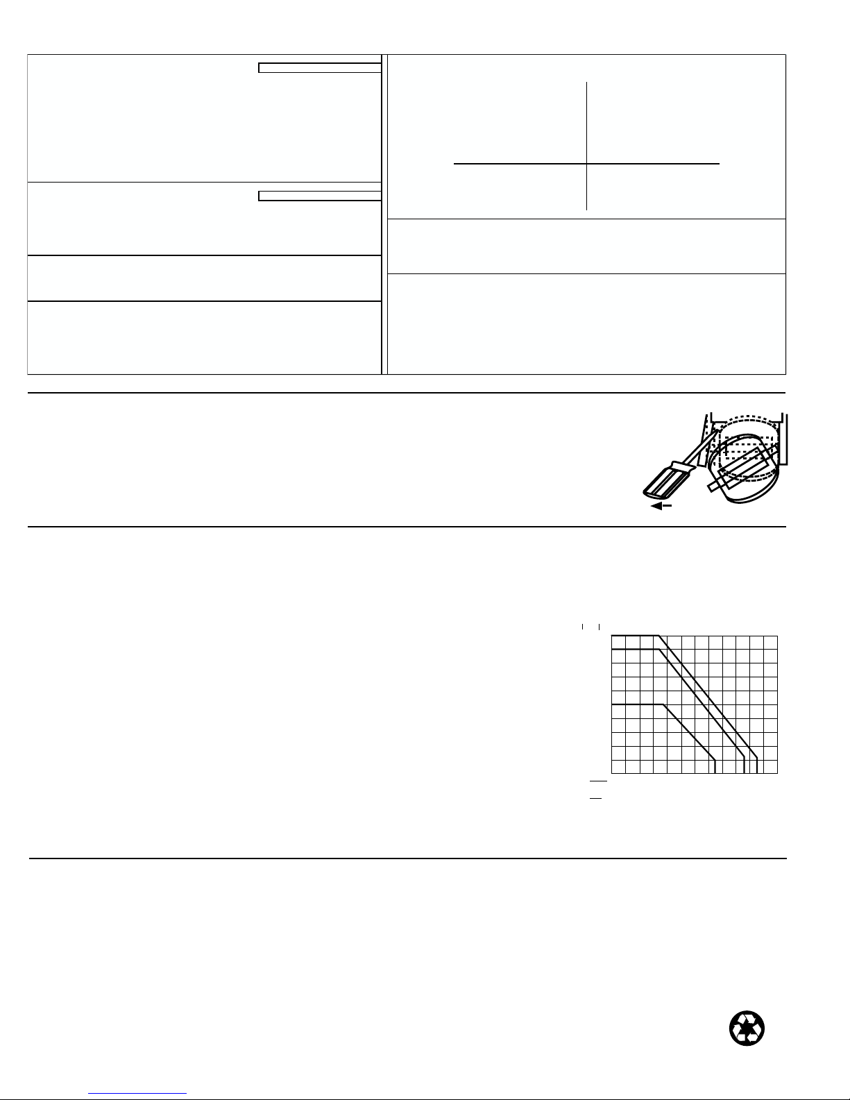
SIZE FITTING TYPE U.S. GAL LITERS SIZE FITTING TYPE U.S. GAL LITERS SIZE FITTING TYPE U.S. GAL LITERS
SCH 80 PVC TEES FOR SCH 80 PVC PIPE GALVANIZED IRON TEES ON SCH 40 PIPE COPPER/BRONZE BRAZOLETS ON SCH 40 PIPE
1/2 IN. PV8T005 480.190 126.867 1 IN. IR4T010 104.538 27.619 2 1/2 IN. BR4B025 18.800 4.967
3/4 IN. PV8T007 257.720 68.090 1 1/4 IN. IR4T012 62.979 16.639 3 IN. BR4B030 12.170 3.215
1 IN. PV8T010 174.670 46.148 1 1/2 IN. IR4T015 46.688 12.335 4 IN. BR4B040 6.960 1.839
1 1/4 IN. PV8T012 83.390 22.032 2 IN. IR4T020 29.459 7.783 5 IN. BR4B050 5.260 1.390
1 1/2 IN. PV8T015 58.580 15.477 6 IN. BR4B060 3.690 0.975
2 IN. PV8T020 32.480 8.581 BRONZE TEES ON SCH 40 PIPE 8 IN. BR4B080 2.130 0.563
2 1/2 IN. PV8T025 21.833 5.768 1 IN. BR4T010 104.538 27.619 10 IN. BR4B100 1.350 0.357
3 IN. PV8T030 13.541 3.578 1 1/4 IN. BR4T012 62.979 16.639 12 IN. BR4B120 0.960 0.254
4 IN. PV8T040 7.626 2.015 1 1/2 IN. BR4T015 46.688 12.335
2 IN. BR4T020 29.459 7.783 SCH 80 IRON SADDLES ON SCH 80 PIPE
SCH 80 CPVC TEES FOR SCH 80 CPVC PIPE 2 IN. IR8S020 32.360 8.550
1/2 IN. CPV8T005 480.190 126.867 COPPER TEE FITTINGS ON COPPER PIPE PIPE 2 1/2 IN. IR8S025 22.220 5.871
3/4 IN. CPV8T007 257.720 68.090 1/2 IN.SK K CUKT005 443.206 117.095 3 IN. IR8S030 13.420 3.546
1 IN. CPV8T010 174.670 46.148 1/2 IN. SK L 414.413 109.488 4 IN. IR8S040 7.660 2.024
1 1/4 IN. CPV8T012 83.390 22.032 3/4 IN.SK K CUKT007 212.156 56.052 5 IN. IR8S050 5.860 1.548
1 1/2 IN. CPV8T015 58.580 15.477 3/4 IN. SK L 191.086 50.485 6 IN. IR8S060 4.090 1.081
1 IN.SK K CUKT010 127.176 33.600 8 IN. IR8S080 2.330 0.616
SCH 80 PVC SADDLES FOR SCH 80 PVC PIPE 1 IN. SK L 119.840 31.662 10 IN. IR8S100 1.530 0.404
2 IN. PV8S020 32.480 8.581 1 1/4 IN.SK K CUKT012 88.218 23.307 12 IN. IR8S120 1.060 0.280
2 1/2 IN. PV8S025 21.833 5.768 1 1/4 IN. SK L 85.451 22.576
3 IN. PV8S030 13.541 3.578 1 1/2 IN.SK K CUKT015 56.962 15.049 SCH 80 IRON SADDLE ON SCH 40 PIPE
4 IN. PV8S040 7.626 2.015 1 1/2 IN. SK L 55.160 14.573 2 IN. IR8S020 26.820 7.086
6 IN. PV8S060 4.162 1.100 2 IN.SK K CUKT020 29.370 7.759 2 1/2 IN. IR8S025 18.800 4.967
8 IN. PV8S080 2.370 0.626 2 IN. SK L 28.605 7.558 3 IN. IR8S030 11.990 3.168
4 IN. IR8S040 6.850 1.810
SCH 80 PVC SADDLE ON SCH 40 PVC PIPE STAINLESS STEEL WELDOLETS ON SCH 40 PIPE 5 IN. IR8S050 5.330 1.408
2 IN. PV8S020 27.350 7.226 2 1/2 IN. CR4W025 18.800 4.967 6 IN. IR8S060 3.760 0.993
2 1/2 IN. PV8S025 18.874 4.987 3 IN. CR4W030 12.170 3.215 8 IN. IR8S080 2.130 0.563
3 IN. PV8S030 12.638 3.339 4 IN. CR4W040 6.960 1.839 10 IN. IR8S100 1.350 0.357
4 IN. PV8S040 6.728 1.778 5 IN. CR4W050 5.260 1.390 12 IN. IR8S120 0.960 0.254
6 IN. PV8S060 3.730 0.985 6 IN. CR4W060 3.690 0.975
8 IN. PV8S080 2.153 0.569 8 IN. CR4W080 2.130 0.563
10 IN. CR4W100 1.350 0.357
CARBON STEEL TEES ON SCH 40 PIPE 12 IN. CR4W120 0.960 0.254
1/2 IN. CS4T005 370.202 97.808
3/4 IN. CS4T007 212.063 56.027 CARBON STEEL WELDOLETS ON SCH 40 PIPE
1 IN. CS4T010 141.138 37.289 2 1/2 IN. CS4W025 18.800 4.967
1 1/4 IN. CS4T012 60.655 16.025 3 IN. CS4W030 12.170 3.215
1 1/2 IN. CS4T015 45.350 11.982 4 IN. CS4W040 6.960 1.839
2 IN. CS4T020 26.767 7.072 5 IN. CS4W050 5.260 1.390
6 IN. CS4W060 3.690 0.975
STAINLESS STEEL TEES ON SCH 40 PIPE 8 IN. CS4W080 2.130 0.563
1/2 IN. CR4T005 358.960 94.838 10 IN. CS4W100 1.350 0.357
3/4 IN. CR4T007 202.610 53.530 12 IN. CS4W120 0.960 0.254
1 IN. CR4T010 127.140 33.590
1 1/4 IN. CR4T012 61.910 16.357
1 1/2 IN. CR4T015 40.410 10.676
2 IN. CR4T020 22.300 5.892
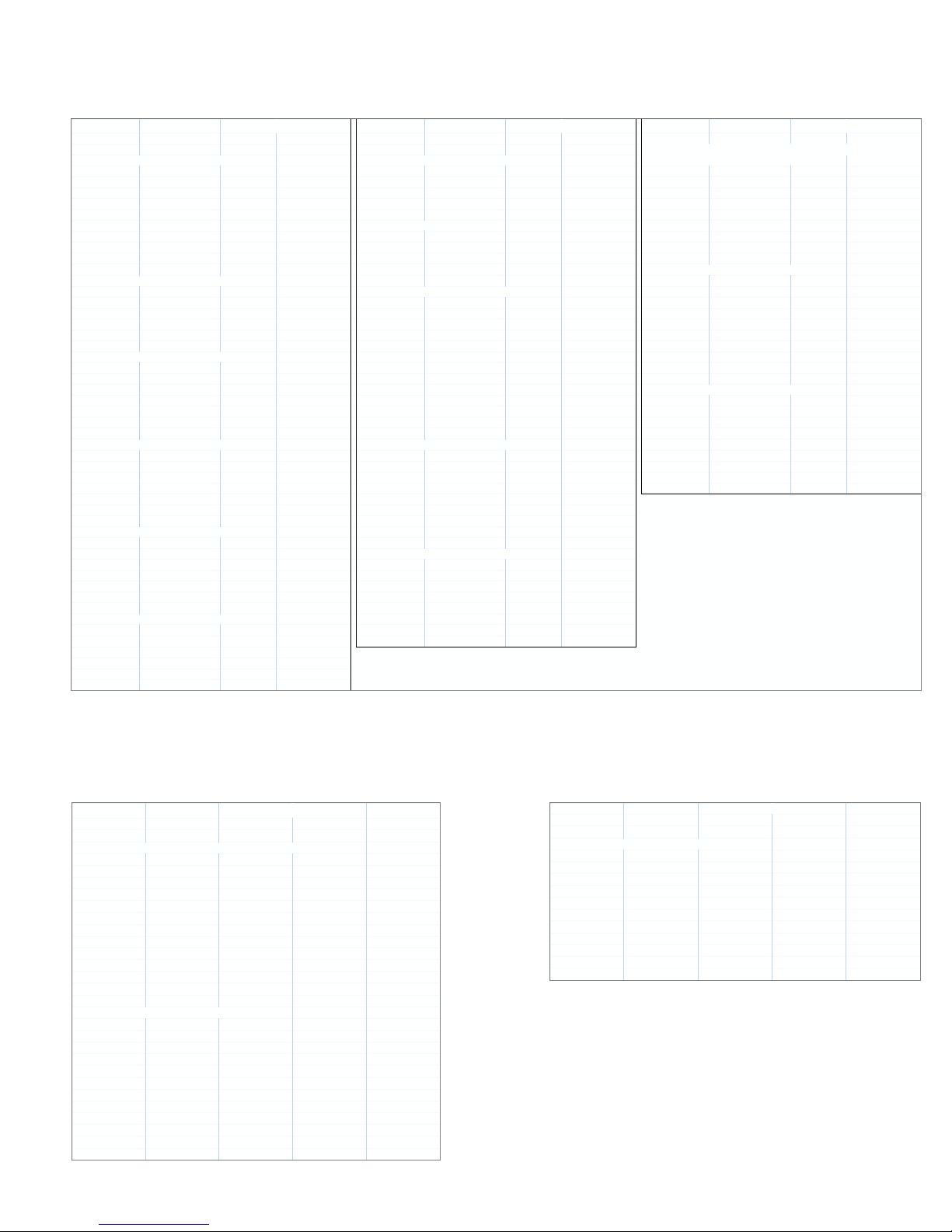
9. K-Factors
The K-Factor is the number of pulses the sensor will generate for each engineering unit of fluid which passes. They are listed in U.S. gallons and in liters. For
example, in a 1 inch PVC pipe, the paddlewheel generates 176.670 pulses per gallon of fluid passing the rotor. K-factors are listed for pipes up to 12 inch. For
pipes over 12 inch, consult your +GF+Signet distributor.
K-Factors DIN Pipes
Conversion Formulas
1 U.S. gallon = 0.003785 cubic meters
0.000003069 Acre feet
8.3454 pounds of water

+GF+SIGNET
Sales Offices:
USA George Fischer, Inc., 2882 Dow Avenue, Tustin, CA 92780/USA, Tel. (714) 731-8800, Fax (714) 731-6201
Switzerland Georg Fischer Rohrleitungssysteme AG, P.O. Box 671, CH-8201 Schaffhausen/Switzerland, Tel. 052/631 1111, Fax 052/631 2830
Singapore George Fischer Pte. Ltd., 15 Kaki Bukit Road 2, KB Warehouse Complex, Singapore 1441, Tel. 65/747 0611, Fax 65/747 0577
Japan Kubota George Fischer, 2-47 Shikitsuhigashi, 1-Chome, Naniwa-Ku, Osaka, 556-91 Japan, Tel. 816/648 2545, Fax 816/648 2565
China Georg Fischer Ltd., Rm 1503, Business Residence Bldg. of Asia Plaza, 2-3 Bldg. No. 5th Qu Anzhenxili, Chaoyang Qu, Beijing 100029,
P.R. China, Tel. 86/10 6443 0577, Fax 86/10 6443 0578
Australia George Fischer Pty. Ltd., Suite 3, 41 Stamford Road, Oakleigh, Victoria 3166, Australia, Tel. 61/3 9568 0966, Fax 61/3 9568 0988
Signet Scientific Company, 3401 Aerojet Avenue, El Monte, CA 91731-2882 U.S.A., Tel. (626) 571-2770, Fax (626) 573-2057
GEORGE FISCHER +GF+Piping Systems
P51590-1/(J-5/97), English © Signet Scientific Company 1994 Printed in U.S.A.
Standard 515 Rotor-X Paddlewheel Flow Sensors All O-rings are Viton® 515 Accessories
Sensor Order No. Order No.
Order No. Body Rotor Pin Rotor Pipe Size Code Rotors Material Code Rotor Pin Material Code
P51530-P0 Polypro. Titanium PVDF (black) 0.5 to 4.0 in. 198 801 620 M1538-2 PVDF (std.) 198 801 181 M1546-1 Titanium 198 801 182
P51530-P1 Polypro. Titanium PVDF (black) 5.0 to 8.0 in. 198 801 621 M1538-4 Tefzel 198 820 018 M1546-2 Hastelloy C 198 801 183
P51530-P2 Polypro. Titanium PVDF (black) 10 to 36 in. 198 801 622 P51546 Tefzel with 198 820 017 M1546-3 Tantalum 198 820 014
P51530-V0 PVDF (natural) Hastelloy C PVDF (natural) 0.5 to 4.0 in. 198 801 623 sleeve M1546-4 Stainless steel 198 820 015
P51530-V1 PVDF (natural) Hastelloy C PVDF (natural) 5.0 to 8.0 in. 198 801 624 P51550-3 PVDF (natural) 198 820 043 P51545 Ceramic 198 820 016
P51530-V2 PVDF (natural) Hastelloy C PVDF (natural) 10 to 36 in. 198 801 625 + Rotor Pin P51550-3 PVDF (natural) 198 820 043
P51530-T0 PVDF (natural) PVDF (natural) PVDF (natural) 0.5 to 4.0 in. 198 801 663 + Rotor
P51530-T1 PVDF (natural) PVDF (natural) PVDF (natural) 5.0 to 8.0 in. 198 801 664
P51530-T2 PVDF (natural) PVDF (natural) PVDF (natural) 10 to 36 in. 198 801 669 Order No. Order No. Description Code
O-Rings Material Code P31542 Sensor cap, PP 198 801 630
319 Wet-Tap Assembly Including Extended 515 Sensor Rotor pin material is Titanium 1220-0021 Viton® (std.) 198 801 186 P31536 Plug, PP 198 840 201
1224-0021 EPR 198 820 006 P31536-2 Plug, PVDF (nat.) 198 840 202
Sensor 1228-0021 Kalrez 198 820 007 with std. cap
Order No. Valve Body Rotor Pipe Size Code
MK319/515-P3 PVC Polypro. PVDF (black) 0.5 to 4.0 in. 198 840 119
MK319/515-P4 PVC Polypro. PVDF (black) 5.0 to 8.0 in. 198 840 120
MK319/515-P5 PVC Polypro. PVDF (black) 10 to 36 in. 198 840 121
319 Wet-Tap Wit
h
out 515 Sensor
Order No. Material Description +GF+ SIGNET 3-8510-XX Integral Sensor Accessories
P31940 PVC 319 Wet-Tap Order No. Description Code
Extended 515 Sensors for 319 Wet-Tap 3-8011 Integral sensor mounting kit with 1/2 in. NPT ports 198 864 500
3-8011-D Integral sensor mounting kit with PG 13.5 ports 198 864 501
Sensor
Order No. Body Rotor Pin Rotor Pipe Size Code Order No. Description Pipe Size Code
P51530-P3 Polypro. Titanium PVDF (black) 0.5 to 4.0 in. 198 840 310 3-8510-P0 Integral sensor, Polypro. 0.5 to 4 inch 198 864 504
P51530-P4 Polypro. Titanium PVDF (black) 5.0 to 8.0 in. 198 840 311 3-8510-P1 Integral sensor, Polypro. 5 to 8 inch 198 864 505
P51530-P5 Polypro. Titanium PVDF (black) 10 to 36 in. 198 840 312 3-8510-V0 Integral sensor, PVDF (natural) 0.5 to 4 inch 198 864 506
Fluid Conditions
515/3-8510-XX Sensor Pressure/Temperature Ratings:
Polypropylene Body:
• 12.5 bar (180 psi) max. @
20 °C (68 °F)
• 1.7 bar (25 psi) max. @
90 °C (194 °F)
PVDF Body:
• 14 bar (200 psi) max @
20 °C (68 °F)
• 1.7 bar (25 psi) max @
100 °C (212 °F)
319 Wet-Tap Assembly
Pressure/Temperature Ratings:
• 7 bar (100 psi) max. @ 25 °C (77 °F)
• 1.4 bar (20 psi) max. @ 66 °C (150 °F)
11. Rotor Replacement Procedure
1. To remove the rotor, insert a small screwdriver between the rotor and the ear of the sensor.
2. Twist the screwdriver blade to flex the ear outward enough to remove one end of the rotor and pin. DO NOT flex the ear
any more than necessary! If it breaks, the sensor cannot be repaired.
3. Install the new rotor by inserting one ear into the hole, then flex the opposite ear back enough to slip rotor into place.
10. Order Information
12. Specifications
General Data
Flow Rate Range: 0.3 to 6 m/s (1 to 20 ft/s)
Linearity: ±1% of maximum range
Repeatability: ±0.5% of maximum range
Pipe Size Range: 15 to 900 mm (0.5 to 36 in.)
Cable Length: 7.6 m (25 ft) can splice up to 60 m (200 ft) without
amplification
Cable type: 2-conductor twisted pair with shield
Materials
Sensor Assembly: Various thermoplastics available. Refer to section 10 for
details.
Electrical
Source Impedance: 8 kΩ
Quality Standards
• FM, CE
• Manufactured under ISO 9001
40
80
120
160
200
3
6
8
11
14
0 40 80 120 160 200
-18 4 27 49 71 93
°F
°C
psi
bar
240
115
515/3-8510-XX - PVDF
515/3-8510-XX - Polypropylene
319 Wet-Tap
PRINTED ON RECYCLED PAPER
Other manuals for Signet 8850-3
4
Table of contents
Popular Accessories manuals by other brands

Yamato
Yamato NeoCool Dip BE201 instruction manual

Vicinoate
Vicinoate 158746.01 user manual

Cyndar Electronic Technology
Cyndar Electronic Technology XD-TOF-25 operating instructions

Minami
Minami Swivel Straight XTS1 instructions

Jabra
Jabra ROX WORELESS Getting started guide

Leviton
Leviton OSMHD-VDW installation instructions