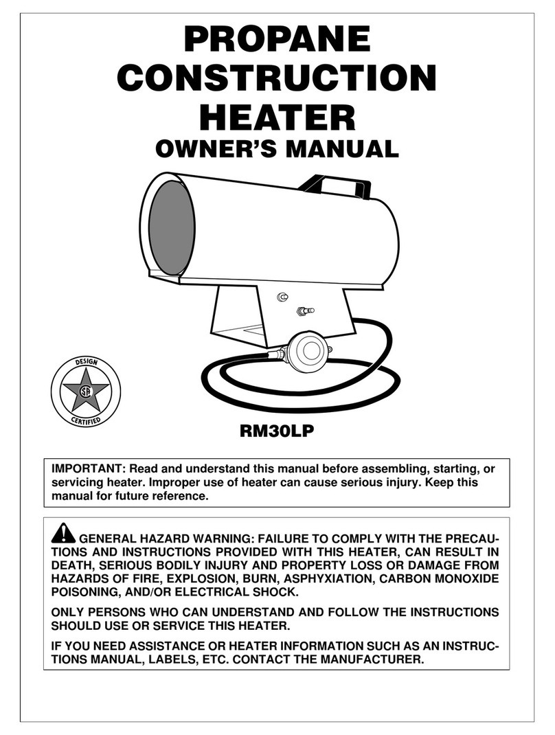
HEATEC HC Series User manual

This document provides instructions for retrofitting
Fireye BurnerLogix controls (Figure 1) to Heatec
HC and HCS heaters. Fireye and BurnerLogix are
trademarks of Fireye, a Kidde Company.
The new Fireye BurnerLogix controls include the
following units:
• Display Module BLV512
• Burner control YB110 with Programmer
Module YP100
These new controls replace older Fireye Flame
Monitor E110 used on control panels (Figure 2)
of HC and HCS heaters until recently. The older
controls are being phased out and will be available
only for a limited time.
The new controls provide some advantages over
the older Flame Monitor controls. Consequently,
some owners may want to upgrade to the new
controls even though the older ones are operating
satisfactorily at the present time.
Retrofitting Fireye®BurnerLogix™Controls
on Heatec HC and HCS heaters
Publication No. 2-09-211
Figure 1 New Fireye Burner Logix controls.
ALARM
HORN
OFF
RESET
OPEN
CIRC. PUMP
OFF ON
HEATER CONTROL
OFF ON
HEATER ALARM
OFF ON
GAS OIL
POWER ON
MANUAL
RESET
AUX. PUMP #1
OFF ON
AUX. PUMP #2
OFF ON
AUX. PUMP #3
OFF ON
BLOWER ON
LIMITS MADE
LOW FUEL
GAS PRESS.
HEATER ALARM
COMB. AIR
AUX. CONTACTS
HIGH FUEL
GAS PRESS.
OIL VALVE ON
HIGH MEDIA
TEMP.
LOW FUEL
PILOT PRESS.
GAS VALVE ON
LOW FUEL
OIL PRESS.
LOW MEDIA
LEVEL
PILOT GAS VALVE
ON
HEATER FUEL
OIL PUMP
AUX. CONTACTS
HEAT DEMAND
E
M
E
R
G
E
N
C
Y
-
S
T
O
P
E
M
E
R
G
E
N
C
Y
-
S
T
O
P
HIGH FLUE GAS
STACK TEMP.
CIRC. PUMP
AUX. CONTACTS
LOW MEDIA
DIFF. PRESS.
HIGH MEDIA
DIFF. PRESS.
FUNCTION DISPLAY RESET SET UP
AUTO
TUNE
RUN
HOLD
Honeywell
ALM
OUT
PV
HIGH MEDIA
TEMP. CONTROLLER
345F
MODULATING
CONTROLLER
SETPOINT
SELECT
RUN
HOLD
Honeywell
ALM
DI %
RSP
OUT
MANUAL
AUTO
LOWER
DISPLAY
FUNCTION
LOOP 1/2
SET UP
SP 350
345
FA
SCRL
MODE
RESET
FLAME-MONITOR
AUTO
FLAME SIGNAL
40
Figure 2. Typical control panel using old Fireye Flame Monitor.
HEATEC TEC-NOTE

Page 2
Do not use Fireye Programmer Module YP100
on a Heatec heater unless the module was
programmed at the Heatec factory. New modules
obtained directly from Fireye or other suppliers
may not be programmed to ensure safe operation
of Heatec heaters. Inappropriate programming
could result in an explosion with serious injuries or
death.
In order to comply with safety codes applicable to
our heaters we reset all new Fireye programmer
modules that we use on our heaters. We lock the
settings to ensure that they cannot be changed
accidentally.
If a heater is operated using a new module with
unlocked settings, those settings will be locked
automatically after eight hours of operation. And
once those settings are locked, they are permament
and cannot be changed.
To make sure that your programmer module has
the appropriate Heatec settings, check all of its
settings shown in the Heatec settings column of
Figure 3. Make this check immediately after
installing the new controller. Heatec settings that
differ from the Fireye factory default settings are
shown in red. Heatec settings that are the same as
Fireye factory default settings are marked same as
Fireye default.
Please refer to Fireye Publication BL-1001
for instructions on use of the keypad to check
factory default parameters. A printed copy of this
document is furnished with Fireye Burner Logix
controls. It is also available as a pdf document
from the Fireye website at: http://www.fireye.net/
pdf/BL-1001.pdf
Figure 3. Fireye factory settings vs Heatec factory settings.
Parameter Fireye Factory Default Heatec settings
Purge time 00:30s 00:60s
Count method DOWN Same as Fireye default
Prove 3-P open at start NO YES
PTFI*MTFI timing 10/10*10/15 Same as Fireye default
Terminal 6 interrupted or intermittent INTRP Same as Fireye default
Prove M-8 open NO YES
Prove M-D open NO YES
Post purge 0:15 Same as Fireye default
3-P Recycle YES Same as Fireye default
M-D WAIT 10m YES Same as Fireye default
PROVE M-D TFI NO YES
Baud rate 9600 Same as Fireye default
Unit address 00 Same as Fireye default
Lock Settings NO YES
DO IR LEARN NO Same as Fireye default

Page 3
INSTALLATION PROCEDURE
1. Disconnect all electrical
power to the heater.
2. Open door of heater
control panel. (See
Figure 2.)
3. Remove old Fireye Flame
Monitor E-110 from base.
(See Figure 4.)
4. Disconnect wires from
base and remove base.
(See Figure 5.)
5. Update the wire numbers
of six of the original
wires as indicated in
Figure 10.
6. Install base for new
Burner Control YB110.
where the old E110 base
was located and connect
wires to base. (See
Figures 6 and 10.)
7. Install new Burner
control YB110 including
Programmer Module
YP100. (See Figure 7.)
8. Install Display Module
BLV512. (See Figure 8.)
9. Remove ribbon cable
from remote reset switch
and install two new wires
as indicated in Figure 11.
(See Figures 9 and 11.)
10. Restore electrical power
to the heater.
11. Check settings of Fireye
Programmer Module
YP100 to make sure they
match the Heatec settings
shown in Figure 3.
Figure 4. Old Flame Monitor E110. Figure 5. Base of E110.
Figure 6. Base for YB110. Figure 7. New Burner Control YB110 and
Programmer Module YP100.
Figure 8. Display Module BLV512. Figure 9. Original reset switch with ribbon
cable.
12. Close door of control panel and start the heater.
13. Check all limit circuits for proper operation. in
accordance with Heatec Tec-Note Publication
No. 7-04-136.

Page 4
Figure 10. Wire connections
ORIGINAL
WIRE NUMBER
ORIGINAL
CONNECTION ON BASE
OF E110
UPDATED
WIRE NUMBER
CONNECT TO
TERMINALS ON BASE
OF YB110
S2 S2 S2 S2
S1 S1 S1 S1
H43 A H43 A
H47 8 H47 8
H40 7 H40 7
(NA) 6 (NA) 6
H37 5 H39 5
H21 13 H38 13
H12 12 H12 12
H13 X H13 X
H36 P H37 P
H48 D H49 D
H49 M H48 M
H22 3 21 3
H2 L2/N H2 L2/N
H1 L1/L H1 L1
H11 11 H11 11
H10 10 H10 10
(NA) (NA) (NA) W
(NA) (NA) (NA) 21
(NA) (NA) (NEW RED WIRE) 22
(NA) (NA) (NA) 23
(NA) (NA) (NA) 16
(GREEN WIRE) (EQUIPMENT GND) (GREEN WIRE) E
Some of the original wires that connect to the base of new Burner Control VB110 have wire numbers that
should be updated. To update a wire number you will need to remove original number and apply the new
number. The wire numbers that have changed are shown above in red. Please mark updated wire numbers on
prints of wiring diagrams originally furnished with your heater. Original wire numbers of some older heaters do
not include the letter H. It is not necessary to update an old wire number just to include the letter H.
Figure 11. Reset switch wire connections
WIRE NUMBER CONNECT FROM CONNECT TO
(MAKE NEW BLACK
WIRE 16 GAUGE)
HEATER TERMINAL L1 ONE TERMINAL ON RESET SWITCH
(MAKE NEW RED WIRE
16 GAUGE)
OTHER TERMINAL ON RESET
SWITCH
TERMINAL 22 ON BASE OF BURNER
CONTROL YB110
© Heatec 2009
Heatec, Inc. 5200 Wilson Road Chattanooga, Tennessee 37410 www.heatec.com (423) 821-5200 (800) 235-5200 Fax (423) 821-7673
This manual suits for next models
1
Popular Heater manuals by other brands
Advanced Radiant Systems
Advanced Radiant Systems KMI Installation, operation and service instructions
DEVOLA
DEVOLA DVSH20MK2S instruction manual
Draper
Draper PSH10B Instructions for

Safe-t-Cover
Safe-t-Cover 800S Series Assembly instructions
Clas Ohlson
Clas Ohlson NS-600B-EW manual
Olimpia splendid
Olimpia splendid CALEO 2 TURBO TIMER Instructions for installation, use and maintenance
