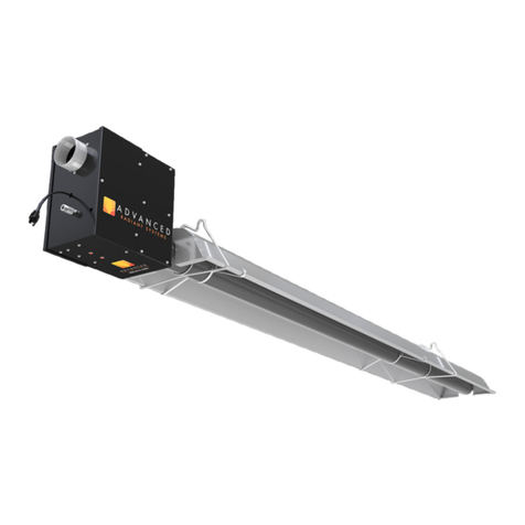
Advanced Radiant Systems KMI Manual

Installation, Operation and Service Instructions
KMI RANGE
HIGH EFFICIENCY
HIGH INTENSITY HEATERS


WARNINGS
WARNING
Improper installation, adjustment, alteration, service
or maintenance can cause property damage, injury
or death. Read the installation, operating and
maintenance instructions thoroughly before
installing or servicing this equipment.
FOR YOUR SAFETY
Do not store or use gasoline or other flammable
vapors and liquids in the vicinity of this or any other
appliance. If you smell gas:
1. Open windows
2. Don’t touch electrical switches
3. Extinguish any open flame
4. Immediately call your gas supplier
OWNER
Retain this manual for reference.
INSTALLER
Read and thoroughly understand these Instructions
before attempting any installation
CAUTION: FIRE OR EXPLOSION HAZARD
Maintain clearance to combustible constructions as
further specified in this manual. Failure to do so
could result in a serious fire hazard. Heaters should
not be located in hazardous atmospheres containing
flammable vapors or combustible dusts. Signs
should be provided in storage areas specifying
maximum safe stacking height.
CAUTION: MECHANCIAL HAZARD
This equipment is designed and approved for indoor
use only.
CAUTION: FIRE OR EXPLOSION HAZARD
This heater is equipped with an automatic ignition
device. Do not attempt to light the burner by hand.
Failure to comply could result in a serious fire and
personal injury hazard.
CAUTION: MECHANCIAL HAZARD
Do not use high pressure (above 1/2psi) to test the
gas supply system with the burners connected,
doing so could result in damage to the burner and
its control components requiring replacement.
Do not install equipment in atmospheres containing
halogenated hydrocarbons or other corrosive
chemicals, doing so may lead to premature
equipment failure and invalidation of the warranty.
CAUTION: SERVICE LIFE RISK
Due to continuous product innovations, we reserve the right to change product specifications without due notice.

CONTENTS
INTRODUCTION ............................................................................................................................. 1
Preface ..............................................................................................................................................................1
The Technology ...............................................................................................................................................1
General information .........................................................................................................................................2
LAYOUT RECOMMENDATIONS...................................................................................................... 3
Layout Considerations .....................................................................................................................................3
Spot Heating .....................................................................................................................................................3
Full Building Heat..............................................................................................................................................4
ENGINEERING SPECIFICATIONS................................................................................................... 5
Energy Supply ...................................................................................................................................................5
CLEARANCE TO COMBUSTIBLES ................................................................................................. 6
INSTALLATION INSTRUCTIONS.................................................................................................... 6
...................................................................................7
Horizontally Mounted High Intensity Heater......................................................................................................................7
Angled High Intensity Heater................................................................................................................................................8
Air Plate Installation Instructions....................................................................................................................9
Gas Connections ...........................................................................................................................................10
Electrical Connections ..................................................................................................................................11
Single-Stage Electrical Connection / Wiring Diagram .................................................................................13
Ventilation .......................................................................................................................................................14
Condensation..................................................................................................................................................14
OPERATION AND MAINTENANCE............................................................................................... 15
Control Operating Sequence .........................................................................................................................15
TROUBLESHOOTING ................................................................................................................... 16
REPLACEMENT PARTS ............................................................................................................... 17
WARRANTY.................................................................................................................................. 18

Page 1
High Efciency - High Intensity KMI_02142017al
INTRODUCTION
Preface
The Technology

Page 2
High Efciency - High Intensity KMI_02142017al
IMPORTANT
General information
This heater is approved for either indoor installation only. Not for use in residential dwellings, refer to rating
plate.
INSTALLATION CODES
GENERAL INSTALLATION AND GAS CODES/ELECTRICAL CODES
AIRCRAFT HANGAR INSTALLATION
PUBLIC GARAGES
PARKING STRUCTURES
Warning
INTRODUCTION

High Efciency - High Intensity KMI_02142017al
LAYOUT RECOMMENDATIONS
Layout Considerations
•
•
•
•
•
Spot Heating
•
•
•
The following charts are intended for guidance only. Specic applications may require other parameters.
HEATER INPUT RATE
btu/hr
MOUNTING ANGLE
0 - 10° ANGLE 30° ANGLE
FEET METERS FEET METERS
20,000 10 - 15 3 - 4.6 9 - 13 2.7 - 4
40,000 12 - 19 3.7 - 5.9 11 - 17 3.4 - 5.2
60,000 14 - 22 4.3 - 6.7 13 - 19 4 - 5.9
90,000 15 - 24 4.6 - 7.3 14 - 22 4.3 - 6.7
120,000 17 - 29 5.2 - 8.8 16 - 25 4.9 - 7.6
Suggested Minimum Mounting Heights

Page 4
High Efciency - High Intensity KMI_02142017al
LAYOUT RECOMMENDATIONS
MODEL
NO. RATE
btu/hr
HEATER
MOUNTING HEIGHT
ft (m) DISTANCE OF
FIRST HEATER
ROW FROM
OUTSIDE WALL
ft (m)
DISTANCE
BETWEEN
HEATERS ALONG
OUTSIDE WALL*
ft (m)
DISTANCE
BETWEEN ROWS
- OUT-SIDE WALL
ROW TO NEXT
INTERIOR ROW
ft (m)
0-10°
ANGLE 30°
ANGLE
KMI-20 20,000 10 - 15
(3 - 4.6) 9 - 13
(2.7 - 4) 6 (1.9) 8 - 20
(2.5 - 6.1) 30 - 60
(9.2 - 18.3)
KMI-40 40,000 12 - 19
(3.7 - 5.9) 11 - 17
(3.4 - 5.2) 10 (3.1) 15 - 30
(4.6 - 9.2) 50 - 80
(15.2 - 24.4)
KMI-60 60,000 14 - 22
(4.3 - 6.7) 13 - 19
(4 - 5.9) 12 (3.7) 20 - 40
(6.1 - 12.2) 75 - 110
(22.9 - 33.5)
KMI-90 90,000 15 - 24
(4.6 - 7.3) 14 - 22
(4.3 - 6.7) 14 (4.3) 30 - 50
(9.2 - 15.2) 90 - 115
(27.5 - 35.0)
KMI-120 120,000 17 - 29
(5.2 - 8.8) 16 - 25
(4.9 - 7.6) 16 (4.9) 40 - 60
(12.2 - 18.3) 100 - 125
(30.5 - 38.1)
AMBIENT AIR
TEMPERATURE
btu/hr per sq ft OF FLOOR AREA TO BE HEATED
AT 50 ft/min OF WIND
15.2 m/min AT 100 ft/min OF WIND
30.5 m/min
40°F / 4°C 150 - 165 165 - 180
55°F / 13°C 75 - 88 85 - 100
Suggested Heat Load
Example:
Two heaters at opposing locations would be preferred
Full Building Heat

High Efciency - High Intensity KMI_02142017al
MODEL
NO.
NOMINAL THERMAL LOAD
WEIGHT (lbs)NATURAL GAS (btu/hr) PROPANE GAS (btu/hr)
KMI-20 21,000 23,000 43
KMI-40 45,000 44,000 68
KMI-60 65,000 66,000 94
KMI-90 90,000 90,000 123
KMI-120 125,000 125,000 170
MODEL NO. "A" (in)
KMI-20
KMI-40
KMI-60
KMI-90
KMI-120
GAS PRESSURES
MAXIMUM MINIMUM
Connection
Natural Gas 14" W.C. 6.5" W.C.
Propane 14" W.C. 12" W.C.
SINGLE STAGE GAS PRESSURE
NATURAL GAS PROPANE
Minimum
Maximum 14" W.C.
Manifold
ENGINEERING SPECIFICATIONS
Energy Supply
Gas Connection
Electrical Connection
Power Consumption
13.80
A19.57
5.90
Single Stage

High Efciency - High Intensity KMI_02142017al
CLEARANCE TO COMBUSTIBLES
22 ³/16"
12 ³/16"
14"
1/2
" NPT Inlet
A
B
CG
F
D
E
Suspended Horizontally Suspended at an Angle Up to 35˚
Note: Venture must
always be located in
the upper position
MODEL
NO.
CLEARANCES TO COMBUSTIBLES (in)
SUSPENDED
HORIZONTALLY SUSPENDED AT AN ANGLE
UP TO 30°
A B C D E F G
KMI 20 15 29 90 22 65 10 90
KMI 40 15 29 95 22 65 10 95
KMI 60 15 32 100 22 68 10 100
KMI 90 15 35 105 24 70 10 105
KMI 120 15 39 110 24 75 10 110
treated or plastered.
such as plastics, vinyl
siding, canvas, tri-ply, etc.
It is the installer's
responsibility to assure that
adjacent materials are protected
from degradation.

Page 7
High Efciency - High Intensity KMI_02142017al
INSTALLATION INSTRUCTIONS
•
•
•
•
•
•
pipeline pressure.
•
High Intensity Mounting Instructions/Congurations
heater for installations.
Horizontally Mounted High Intensity Heater
Minimum Mounting Heights (horizontally) relative to Air Temperature
MODEL
NO.
CLEARANCES (in)
RELATIVE TO AIR
TEMPERATURE
59°F 50°F 41°F
KMI 20
KMI 40
KMI 60
KMI 90
KMI 120
Mounting Hardware
BEAM CLAMP SUSPENSION FOR
WOODEN MAIN BEAM
PIPE RING
OR CLEVIS

Page 8
High Efciency - High Intensity KMI_02142017al
INSTALLATION INSTRUCTIONS
Angled High Intensity Heater
Minimum Mounting Heights (angled at 30°) relative to Air Temperature
MODEL NO.
CLEARANCES (in)
RELATIVE TO AIR TEMPERATURE
59°F 50°F 41°F
KMI 20
KMI 40 202
KMI 60
KMI 90
KMI 120
ITEM
NO. DESCRIPTION
1Angled suspension
1 set (AW 84/II)
2Accessories
1 set (AW 84/II)
KMI-20 KMI-40 KMI-60 KMI-90 KMI-120
Hole Spacing 'A' (in)
Weight (lbs) 31 48.5 66.1 86 119

Page 9
High Efciency - High Intensity KMI_02142017al
INSTALLATION INSTRUCTIONS
Air Plate Installation Instructions
M5 SCREWS (QTY 4)
VENTURE NECK
AIR PLATE
ORIFICE
ORIFICE HOUSING
SINGLE STAGE
WARNING
◊ Before the orice housing is mounted to the Venturi neck, the Air Plate and orice sizes must be
compared with the Rating plate specications.
1.
2.

High Efciency - High Intensity KMI_02142017al
Gas Connections
INSTALLATION INSTRUCTIONS
INCORRECT POSITIONS
CORRECT POSITIONS
HEATER
MOVEMENT
HEATER
MOVEMENT
HEATER
MOVEMENT
HEATER
MOVEMENT
WRONG WRONG
WRONG
WRONG
3" MAX. DISPLACEMENT
12"
HEATER
MOVEMENT
WARNING
◊ Flexible connector should not be under tension when connected to the heater. Refer to gure
above.
◊ It is recommended to test leak the system before connecting the heater to the gas line as the leak
test may damage the gas valve.
•
•
•
•
issues.
GAS VALVE
CORRECT POSITIONS
GAS VALVE
INCORRECT POSITIONS
WARNING:
GAS PRESSURE
SWITCH MUST
REMAIN IN
HORIZONTAL
POSITION

Page 11
High Efciency - High Intensity KMI_02142017al
Electrical Connections
WARNING
◊ For your safety, shut off the main gas valve, and disconnect all electrical supply to the High
Intensity Unit.
◊ Ensure the heaters are properly grounded.
◊ Perform all work in accordance with local codes or the National Electric Code ANSI/NFPA 70 or
Canadian Electrical Code CSA C22.1.
◊ Connect the Igniter cable, Flame sensor wire and the ground wire as illustrated below.
◊ This appliance is equipped with a safety control system designed to shut the burner off in the
event of inadequate gas pressures.
INSTALLATION INSTRUCTIONS
FLAME SENSOR WIRE (PINK)
GROUND WIRE (GREEN/YELLOW)
IGNITOR CABLE (BLACK)
CONNECT TO
GAS SUPPLY

Page 12
High Efciency - High Intensity KMI_02142017al
INSTALLATION INSTRUCTIONS
L1
N
HUMIDISTAT
L1
N
FAN #2
FAN
RELAY
FAN #1
When using a humidistat to control exhaust
fans, wire the humidistat to cause the fan to
operate on humidity rise, NOT humidity fall.
Depending on fan horsepower, a relay may or
may not be needed.
Electrical Connections (continued)
WARNING
◊ Do NOT connect the Igniter cable, ame sensor wire and ground wire together!
◊ The Igniter cable and Sense cable have different size connection that match the appropriate
connection on the igniter. The ground wire is connected directly onto one of the adjacent studs.
•

High Efciency - High Intensity KMI_02142017al
INSTALLATION INSTRUCTIONS
Single-Stage Electrical Connection / Wiring Diagram
•
•
TH
V1
24V
V2
GND
S1
DSI
HV
THIS BLUE WIRE
IS ONLY USED WITH CNE
CONTROL MODULE
YELLOW
GREEN
BLUE
BROWN
RED
GAS
PRESSURE
SWITCH OPTIONAL FIELD SUPPLIED / WIRED
RED
GREEN
PINK
TSTAT*
TSTAT*
L1
NEUTRAL
TRANSFORMER
120V
24V
GAS VALVE
FLAME SENSOR
IGNITER
GREEN
BURNER

Page 14
High Efciency - High Intensity KMI_02142017al
INSTALLATION INSTRUCTIONS
Ventilation
details. See local codes for guidance.
Verify applicable local codes in the USA as requirements change by jurisdiction.
•
details.
•
Condensation
•
•
•
•

High Efciency - High Intensity KMI_02142017al
OPERATION AND MAINTENANCE
•Ensure the gas supply line has
•
•
•
Control Operating Sequence
Energizing the system
1.
2.
Reconnection after shut-down on fault
Re-ignition
Controlling / Checking Manifold Pressure
1.
2.
WARNING
◊ Do NOT operate the Infrared Heater if the gas pressure is below 6.5" W.C. for natural gas and 12"
W.C. for propane.

High Efciency - High Intensity KMI_02142017al
TROUBLESHOOTING
SYMPTOM POSSIBLE CAUSE CORRECTIVE ACTION
Heaters will not turn off Defective thermostat Repair or replace
Stuck gas valve
Gas Odor Loose pipe connection
Verify all connections
are sealed by using an
appropriate leak test
Burning of gas/air mixture
inside venturi (ashback)
Cracks between or across ceramic grids Replace burner head
assembly
Excessive drafts Shield or relocate heater
Heaters Cycles on/off
Excessive drafts Shield or relocate heater
Flame sense not grounded Verify wiring and correct
Low gas pressure Verify and correct
Low surface temperature on
ceramic surface
Dirty or plugged ceramics See cleaning maintenance
Low inlet gas pressure Verify and correct
Replace manifold
Verify capacity of fuel supply
lines
No spark, no ignition
Verify and correct/replace
Control module defective
Heater sparks but will not light
Check shut off valve and
combination gas valve
Defective gas valve solenoid Verify and correct/replace
Defective electronic control
Heater lights but 'locks out'
after about 10 seconds
Poor ground Verify and correct/replace
Reversed polarity on electric supply
Check continuity of sense
electrode
Defective electronic control Verify and/or replace
This manual suits for next models
5
Table of contents
Other Advanced Radiant Systems Heater manuals
Popular Heater manuals by other brands

Perel
Perel FH0005 user manual
Dimplex
Dimplex DuoHeat Duo300N installation instructions

GoodHome
GoodHome duala 5059340010984 manual

Tamarack Industries
Tamarack Industries Thawzall XHR700 Operator's manual
Stelrad
Stelrad ELECTRIC Series quick start guide
Space-Ray
Space-Ray VF80-L5 DSI Installation and operation instruction

Bastilipo
Bastilipo RC-Ecofluid-7 instruction manual

AERMEC
AERMEC CLIMAFON 12P manual
Aladdin
Aladdin Tropic S181 instruction manual

Eterna
Eterna PAT2000W Safety and installation instructions

Harbor Freight Tools
Harbor Freight Tools 67118 Set up and operating instructions
Schuller
Schuller HEAT VULCAN Assembling instructions
