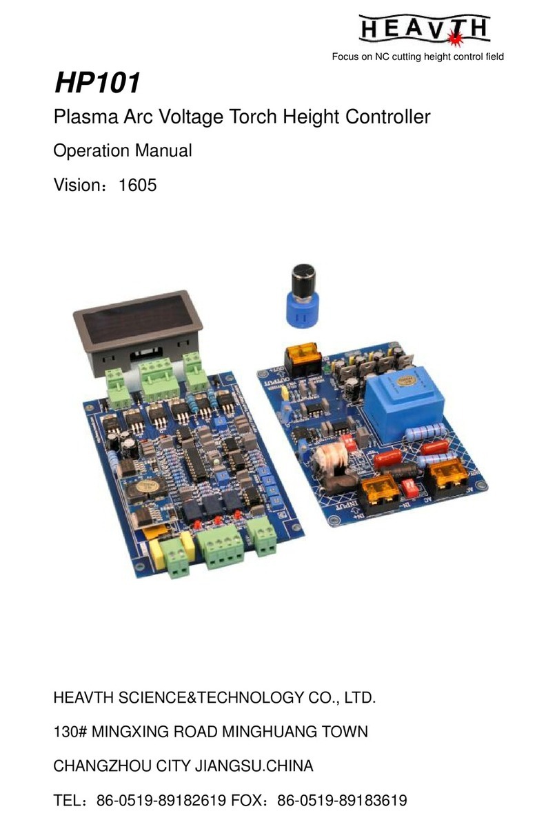
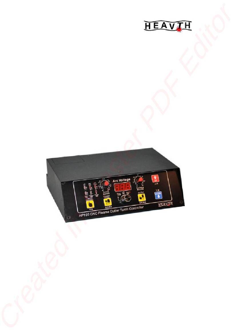
HEAVTH HF100 User manual

HF100
Capecitance Height Controler
TECHNICALMANUAL
VISION 1302
CHANGZHOUHEAVTHSCIENCE&TECHNOLOGYCO.,LTD.
136# HUBINROADNIUTANG TOWNCHANGZHOUCITYJIANGSUINCHINA
TEL 86-0519-89182619
FOX 86-0519-89183619
Http://www.heavth.com

HF100 CapecitanceHeightControler
http://www.heavth.com
-2- 页共14 页
TABLEOFCONTENTS
1 IMPORTANTINFORMATION ................................ 5
1.1 SERVICE ASSISTANCEAND CONTACT INFORMATION............................... 5
1.2 RECEIVINGAND UNPACKING ................................................................. 5
1.3 SAFETY CONSIDERATIONS ....................................................................5
1.4 PRE-INSTALLATION CONSIDERATIONS ................................................. 5
1.5 REPLACEMENT PARTS ........................................................................6
PartNames ................................................................................ 6
1.6 CONFIGURINGTHE LIFTER MECHANICS ................................................. 6
Motor............................................................................................ 6
2 GENERALDESCRIPTION .................................. 7
2.1 GENERAL DESCRIPTION ..................................................................7
2.1.1FrontPanelComponents ..............................................................9
2.1.2Modes........................................................................................... 10
2.1.2.1Auto mode...................................................................................... 10
2.1.2.2Manualmode................................................................................10
AutoandManualModeSpecifications....................................10
2.1.3LimitSwitches ............................................................................. 10
LimitSwitches Specifications.........................................................10
3 INSTALLATION.........................................11
3.1DEFAULTSETTINGSANDDIPSWITCH............................................. 12
3.1.1PositionSignalandRemote OperatorControlSettings ............ 12
3.1.2ClockFrequencyandMaximumMotorCurrent........................ 14
4 START-UPCHECKS..................................... 15
DirectionsforP16Pin
Manual/AutoandUp/Downswitches......................................... 15
4.1ADJUSTINGTHE MEASURING SYSTEM...................................................16
4.2CLEARANCEAND SENSITIVITY TUNING..................................................17
5 DRAWINGS AND DIAGRAMS............................... 18

HF100 CapecitanceHeightControler
http://www.heavth.com
-3- 页共14 页
1IMPORTANT INFORMATION
1.1 SERVICE ASSISTANCE AND CONTACT INFORMATION
Forserviceassistance, havethe following information available:
•HF100 model, part andserialnumberlocated on alabel
•Type of cutting application youareusing
You can contactourat:
TEL:086-0519-89182619
FOX:086-0519-89183619
1.2 RECEIVINGAND UNPACKING
Afterreceivingthe HF100 youshould:
•Carefully, unpackand inspect theequipment.
•Comparethe received shipment withthe packing list.
•Report anydamage tothe carrierand yourrepresentative.
•Storeequipment that willnot beused inaclean, drylocation.
•Takeappropriateprecautionstoprevent moisture, dust and dirt
fromaccumulatinginstorage and installation areas.
1.3 SAFETY CONSIDERATIONS
Safetypracticesshouldnot be an afterthought. Beforeinstallingor
servicing the controller,
reviewand followapplicablepoliciesandprocedurestoensure
workersafety.Machinerymust be inasafestateand you must be
awareof anyadditionalhazardsthat can arise.
1.4 PRE-INSTALLATION CONSIDERATIONS
Beforeinstalling the HF100:
•Check tobe surethat you haveallof the required parts. Referto
P6of thismanual.
•Familiarizeyourself withthe partsofthe HF100 byreviewing P4
inthismanual.
•Check tobe surethat the torchliftermotorsyou areusing withthe
HF100 arewithinthe acceptablerange.
•Reviewthe instructionsforConfiguring theLifterMechanics in
section1.6of thismanual.
1.5 CONFIGURING THE LIFTER MECHANICS
Properconfiguration of the torchliftermechanismisan important
factorforestablishing theaccuracy of yourcuttingsystem. Besure
that:
•Gearreduction isselected onthe torchliftersothat themaximum
suspension speed doesnotexceed 3000 mm/min(120 IPM). If
higheraccuracy isrequired, maximumsuspension speed should
be set to1500 mm/min(60 IPM).
•Gears, racks and spindleshaveminimalbacklash.
•Oversizingisavoided. Themass ofmoving parts,including
armatureinertiamust be assmall aspossible.Motorswithlow
nominalRPMarepreferred.
•OnlyDC motorswiththe followingratingsareused:
MOTORRATINGS DC MOTOR
MOTORVOLTAGE DC24V
MAX CURRENT 6A

HF100 CapecitanceHeightControler
http://www.heavth.com
-4- 页共14 页
1.6 PARTS
HF100 Part Names
HF100-Linclude connector,high-frequency cable
HF100-Linclude connector,high-frequency cable,flexiblecoupling,
torchclamp,ring sensor。

HF100 CapecitanceHeightControler
http://www.heavth.com
-5- 页共14 页
2GENERAL DESCRIPTION ANDSPECIFICATIONS
2.1 GENERAL DESCRIPTION
The cutqualityforthermalcutting processesisaffected bythe
amount of clearancebetween the torchtipandcutting material.
Automaticcontrolof the clearancespan letsyou makeasmooth,
qualitycut athigherspeedswiththe least amount of dross.
HF100 letsyou achieveand maintainthe optimumamount of cut
clearanceand canprovidethe following economicaladvantages:
•Less preparation timebecausetheHF100 controllerquickly
establishesthecorrect amount of clearance.
•Increased productivityasaresult ofhighercutting speeds.
•Optimumcut quality,reducingoreliminatingthe need for
secondaryprocessing.
•Identicalcut qualityon allmachines.
•FullyautomaticCNC machines.
The HF100 controlleralsoprovidesthefollowing advantages:
•Clearanceismeasured using acapacitivesystemallowing
reproduciblesettingandmaintenanceof the onceadjusted
clearance.
•The liftermotoriscontrolled byatransistorized H-bridge Pulse
WidthModulated (PWM)amplifierusing armaturevoltagefeedback
and adjustablecurrentlimitation.
•Forautomation purposes, theintegratedcontrollogicoffersan
In-position signalthat can alsobe usedtodetect cut-outsorcollision
withtip-ups.
•Automaticretract ofthe torchif thehigh-frequency cableisbroken
ordamaged.You can override thisfeaturewhen inManualmode and
continue cutting untilthe problemcan be corrected.
•AutomaticretractinManualmode ifacollision occurswithwork
pieceortip-up.The retract actionstopswhen collision iscleared.
•Visualfault codestoaidinquick troubleshooting.
•The functionsareimplemented inasinglecontrolboxthat also
containstheadjustment knobsforclearanceand sensitivity.
•Upgrade compatibletoHFA2controller
HF100TECHNICAL DATA
MainsSupply AC24V 10%,50/60 Hz, 150 W
LifterMotor 24 VDC MOTOR
ENV. Temperature
ControlBox -10℃∽60℃
HFCable -55℃∽200℃
SenserDistance 5mm-20mm,adjustable。
Accuracy 0.2mm
Lengthof HFCable 1000mm
SensorType Ring
SensorDimensions Outerdiameter80 mm,
Innerdiameter40 mm
Housingdimensions 180mm x100 mm x65 mm(L×W×D)
Weight controlbox0.9kg
controlboxwithsensorcomponents1.3kg

HF100 CapecitanceHeightControler
http://www.heavth.com
-6- 页共14 页
2.1.1 FRONT PANEL COMPONENTS
C
onnectorX2
TO LIFTER
C
onnectorX1
TO CNC
HF
C
onnector
DISTANCE
AUTO TEST
SENSITIVITY
DOWN
UP

HF100 CapecitanceHeightControler
http://www.heavth.com
-7- 页共14 页
2.1.2 MODES
2.1.2.1AUTO MODE
Whenthe contactsofthe Automatic/Manualswitchareclosed, the
HF100 isinAutomaticmode. The torchmovestothe configured
clearancefromthe workpieceand maintainsthatlocation even when the
positionof the workpiecechanges.
Using the Up/Downswitchmanually, and whileinAutomaticmode,
overridesthe automaticheightadjustment configuration. When the
Up/Downswitchisreleased, thetorchmovesback totheclearance
setting configured inthe automaticheightadjustment.
2.1.2.2MANUAL MODE
Whenthe contactsofthe Automatic/Manualswitchareopen, the
HF100 isinManualmode.The positionofthetorchiscontrolled using the
Up/Downswitchesandtheliftermovesatthe maximumspeed.When the
Up/Downswitchisreleased, theactionof thelifterisstopped using
dynamicbraking toallowforexactmanualpositioning. If boththe
Up/Downinputsareoperated at the sametime, the torchmovesupward.
Automatic andManual Mode Specifications
voltage range 0 TO 5VDC
greaterthan4voltsautomatic
less than 2volts manual
maximuminput current 10 mA
2.1.3 LIMIT SWITCHES
Limit switchesimpede the movement of the torchlifterwhen theyare
triggered. The HF100 supportsonlynormally
closedlimit switchessothat malfunctioning limit switchescan be
recognizedbythe control.
Limit Switch Specification Information
voltage range 0 TO 5VDC
greaterthan4voltsthe torchlifterisdisabled
less than 2volts the torchlifterisenabled
maximuminput current 10 mA
3INSTALLATION
The followingsection providesyou withtheproceduretofollowwhen
installingthe HF100. Someof the stepsdirectyou toothersectionsinthis
manualthat provide youwithmoredetailed instruction.
1. Attachthe flexiblecouplingtothe coaxialtube using theM10 thread.
Tighten the locking nut usingan 11/16 inch(17mm)wrench. The flexible
coupling locatedbetween thecoaxialtube andring sensorletsthe sensorring
deflectincaseof acollision.
2. Attachthe ring sensortothe flexiblecouplingand tighten theattachment
screwusing aPhillips-head screwdriver. Position the sensorsothat thetorch
isaligned inthecenterof the ringtoensureproperoperation. Alignthe tipof
the torchand the loweredge of the ring sensortoachievehigh resolutionand
avoidcollisionsbetween thesensorring and torchtip.The sensorring canbe
installedashighas1/8of an inch(3mm)abovethe torchtip.
3.Determine amounting locationforthe HF100.Keep the following pointsin
mind:
Toavoidoverheating and potentialdamage tothe controlboxfromcutting

HF100 CapecitanceHeightControler
http://www.heavth.com
-8- 页共14 页
process fumes, Donot chooseamountinglocationdirectlyabovethe torch.
Find amountinglocation towardsthe sideorback of the torchlifterunit.
Choosealocation forthe HF100 thatletsyou access allfour(4)of thescrews
thatfasten the frontcovercontrolboxtothe back plateandcompletelyremove
the controlboxfromthe back panel.
4. Mount the HF100 using twoM4screws(not included)withamaximum
lengthof3/10”(8mm).
5. Completelyremovethe four(4)screws, twoon eachsideof theHF100,
and thenremovethe controlboxfromthe backplate. Savethescrewsforlater
use.
6. Re-attachthe controlboxtothe backplatebut do not secureusing the
screws.
7. Attachoneend of ahigh-frequency cabletothe top of the coaxialtube
usingthe Bayonet NeillConcelman (BNC)connector.When determining the
lengthof HFcabletouse,be suretochoosealengththat accommodatesfor
the fullloweringof thetorch.
8. Attachthe free end ofthe HFcabletothe controlboxusing theBNC
connector.
9. Attachthe wiresfromthe liftermotorand lifterlimit switchestoa
connectorand then tothe controlboxat the X2receptacle. Besuretoinstall
the keyplug intothe connectortopreventcrossing the X1and X2connections.
Toreducenoiseemission,20AWG (0.5mm2)shieldedcableisrecommended.
Filtersconsisting of aresistorand capacitorcan be connected onlydirectlyto
the motor. RefertoFigure7forwiring connections.
10. Connecta12 AWG (2.5mm2)ground wiretothe groundscrewlocated
on the controlboxand then, tothe machine ground railof yourcutting system.

HF100 CapecitanceHeightControler
http://www.heavth.com
-9- 页共14 页
3.1 Setcontroller
3.1.1 Collision output to CNC
HF100 hasAnti-collision function,itiseffectiveon bothmanual/automode.
Whensteelorotherconductiveitemtouchessensorring, torchlift up, and the
collision signalissentout fromthe Pin3 of 7-pinsocket(OCdoor), when CNC
receivesthissignal,machine pausesand waitsfortreatmentofcollision.When
collision happens, the LEDindicator(collision)on operation panelturnson.
Normallyhuman’shand touchessensorring,indicatorwouldturnon and
send out collision signal. If userchangesHFcable, orHFcablespecchanges,
indicatormight turnon,likefollowsituation, HFcableshort-circuit, onceit
happens,indicatorturnson, torchlift up. It couldbe confirmed bycheckingthe
HFcableshieldnet and Signalconnect ornot.HFcablegetslonger,it needs
toadjusttofind the Balancepoint, then THC can workrighton Automode,and
indicatorwillturnoff.
Collision SignalDetails
type open-collectorsignalthat can operateanexternalrelay
connection X1PIN7、PIN3
input voltage 50 VDC maximum
input current 0.15 Ampmaximum(<1mAof leakage)
RP4
Balance
point
adjustor
RP3
Disconnection
adjustor
D
iscon
Jumper
Fuse
SP2
Frequency/current
Set

HF100 CapecitanceHeightControler
http://www.heavth.com
-10- 页共14 页
Collision SignalConnection
3.1.2 SPEED CONTROLLER CLOCKFREQUENCY ANDMAXIMUM MOTOR CURRENT
Usethe toggleswitchesonDIPswitchSP2toconfigurethe speed
controllerclock frequency and maximumliftermotorcurrent value.
Setting ToggleSwitch1of DIPSwitchSP2
Switch: Tothe ONposition Tothe OFFposition
1 18KHz 9KHz
Setting the controllerclock frequency to18 kHzrequiresthat you takethe
propershielding and grounding precautionswhen running thelinestothe lifter
motor. Following the properwiring precautionsensuresthat thepermissible
noisefieldintensityisnotexceeded.
Using acontrollerclock frequency of9kHzmeetsthe 10kHzinterference
suppressionrestrictions;howeverawhistling noisemaybe heard.
The positionoftoggleswitches2,3and 4on DIPswitchSP2determine the
maximumcurrent forthe liftermotor.
Todetermine the correctamperage maximumvalueforthe liftermotor,
refertothe liftermotorrating plateorthe instructionmanualthataccompanied
the motor. Then,refertoTableI toset thetoggleswitchesforDIP
Setting ToggleSwitches2, 3and 4of DIPSwitchSP2
Set the toggleswitchestothisposition:
Switch2 Switch3 Switch4 maximum
current
OFF OFF OFF 4A
OFF OFF ON 3A
OFF ON ON 2A
ON ON ON 1A
HF100
Collision
Signal
COM
DC
POWER
CNC
X1
7
3
RELAY
24V +24V
0V

HF100 CapecitanceHeightControler
http://www.heavth.com
-11- 页共14 页
4START-UP CHECKS
Beforeperforming thestart-upchecks, besurethat youhavesuccessfully
completedthe installationstepsoutlinedinsection3ofthismanual.
1. DisconnecttheConnectorfromtheX1receptacle.
2. Check theresistancebetween theAutomatic/ManualandUp/Downswitches
usinganohmmeter.
Placeone ofthe
leadsof the
ohmmeterinpin
number:
Placetheother
leadof the
ohmmeterinpin
number:
Then, The ohmmeterdisplay
shouldshow:
6 3 pushthe torch
UP
switch
<10Ohms
5 3 pushthe torch
DOWNswitch <10Ohms
4 3 AUTO MODE <10Ohms
3. ReconnecttheConnectortoX1andset the liftertoManualmode.
4. Applythemainpowersupplytothecontroller. The liftermust notmove.
5. VerifytheLEDlocated onthefront panelof theController.
6. Brieflypushthe Up/DownswitchtotheDOWNposition.Thetorchliftermust
traveldownwardsforaslongasthe switchispressed.BrieflypushtheUp/Down
switchtotheUPposition.The torchliftermust travelupwardsforaslongastheswitch
ispressed.Ifthelifterdirectionof traveldoesnotcorrespondtotheUp/Downswitch
positions,thefieldorarmatureconnectionsof theliftermotormustbechanged.Refer
tosection6inthisdocumentfortroubleshooting information.
7. Verifythat theliftertravellimit switchassignmentscorrespondwithtorchlifter
directionofmovementbyperformingthefollowing checks:
MovetheUp/DownswitchtotheDOWNpositionandthentriggerthe
correspondingdowntravellimit switchbyhand. The liftershouldstopwhenthelimit
switchistriggered.
MovetheUp/DownswitchtotheUPpositionandthentriggerthecorresponding
up travellimit switchbyhand.Theliftershouldstopwhen thelimit switchistriggered.
OperatetheliftermanuallyusingtheUp/Downlimit switches. Theliftershould
stopwhen ithitsthetravellimit switch. Then,youshouldbeabletoback-offof the
triggered limit switchbyreversingthe direction of the lifter.
8. Adjust themeasuringsystembyperformingthestepsoutlined insection4.1on
page 16of thismanual.
4.1 ADJUSTINGTHE MEASURING SYSTEM
Toprovidethe properamountof clearance,ahigh-frequencycurrent isused to
determine thecapacitancebetweenthe sensorringandworkpiece. Due tovarying
high-frequency cablelengthsandsensorrings, youmust fine-tunethemeasuring
systembeforeperformingacuttingsequence.
Afterreplacingahigh-frequencycableorsensorring,re-adjustthemeasuring
systemusingthe stepsoutlinedbelow.
Toadjust the measuringsystem,perform thefollowing steps:
1. Check tobesurethatthemeasuringsystemiscompletelyinstalledand
correctlywired. Double-check tobesurethatthe:
HF100isconnectedtothe sensorringcomponentsbywayoftheappropriateHF

HF100 CapecitanceHeightControler
http://www.heavth.com
-12- 页共14 页
cable.
The sensorismountedon thetorchandthat thetorchnozzleispositioned inthe
middleofthering.
The followingpartsareconnected totheprotectiveconductorbus: machineearth
ground(GND).torchtableandgroundscrewonHF100usingacablewitha
cross-section of14AWG (2.5mm2).
2. First, setonManualmode,lift torchupover20mmagainststeelplate.
3. TurntheSENSITIVITYand DISTANCEinthe middleposition.
4. Press AutoTestbuttontoturnAutoon, iftorchliftdown, meansAutoHeight
istoolow,thenadjustRP4clockwisetoraisethe autoheight.If torchliftup, means
Autoheight istoohigh, turnanti-clockwise.
Pleaseprotecttheadjust Resistortoavoiddamage, DoNotexceed1/4roundon
everyturn, andmakerecordofturndirection.
5. Attachthecontrolboxtotheback panelandsecurewithfour(4)screws.
6. Configuretheclearancedistanceandsensitivity.

HF100 CapecitanceHeightControler
http://www.heavth.com
-13- 页共14 页
5DRAWINGS AND DIAGRAMS
Collision Signal
AUTO/MANUAL(OPEN)

HF100 CapecitanceHeightControler
http://www.heavth.com
-14- 页共14 页
CollisionSignal
This manual suits for next models
1
Table of contents
Other HEAVTH Controllers manuals
Popular Controllers manuals by other brands

LOVATO ELECTRIC
LOVATO ELECTRIC ATL600 instruction manual
Skope
Skope SCS Connect Technician manual

GZAIR
GZAIR Grow PT02 quick start guide
YASKAWA
YASKAWA Z1000U Series quick start guide
FASTRON.
FASTRON. VISION Series Programming guide

National Instruments
National Instruments sbRIO-9605 Operating instructions and specifications
