Heidelberg Engineering MLA 150 User manual
MLA 150
User manual

2
1. Exposing with MLA 150
A. Start
B. Setup job
C. Expose
D. End
2. Design conversion
3. Troubleshooting main error/issues - to be added
4. Mask Fabrication (Backup VPG 740) - to be added
5. MLA 150 - 2 / Greyscale - to be added
6. Theory about the machine - to be added

1.Exposing with MLA 150
4
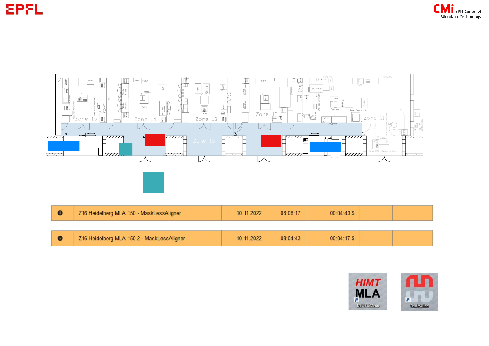
1. A –Start
1. log in on CAE PC
Level +1
2. Start the menu
d
→If not started yet, open the desktop applications (control and camera)
5
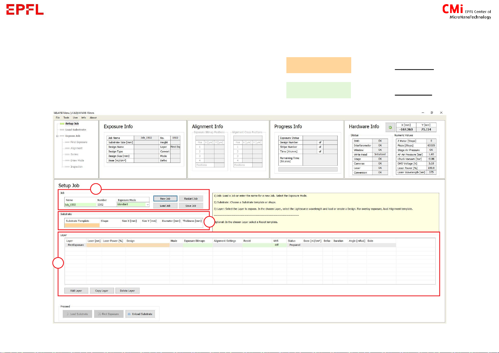
1.B –Setup job
First be aware of this colour rule regarding boxes = input required
= input optional
6
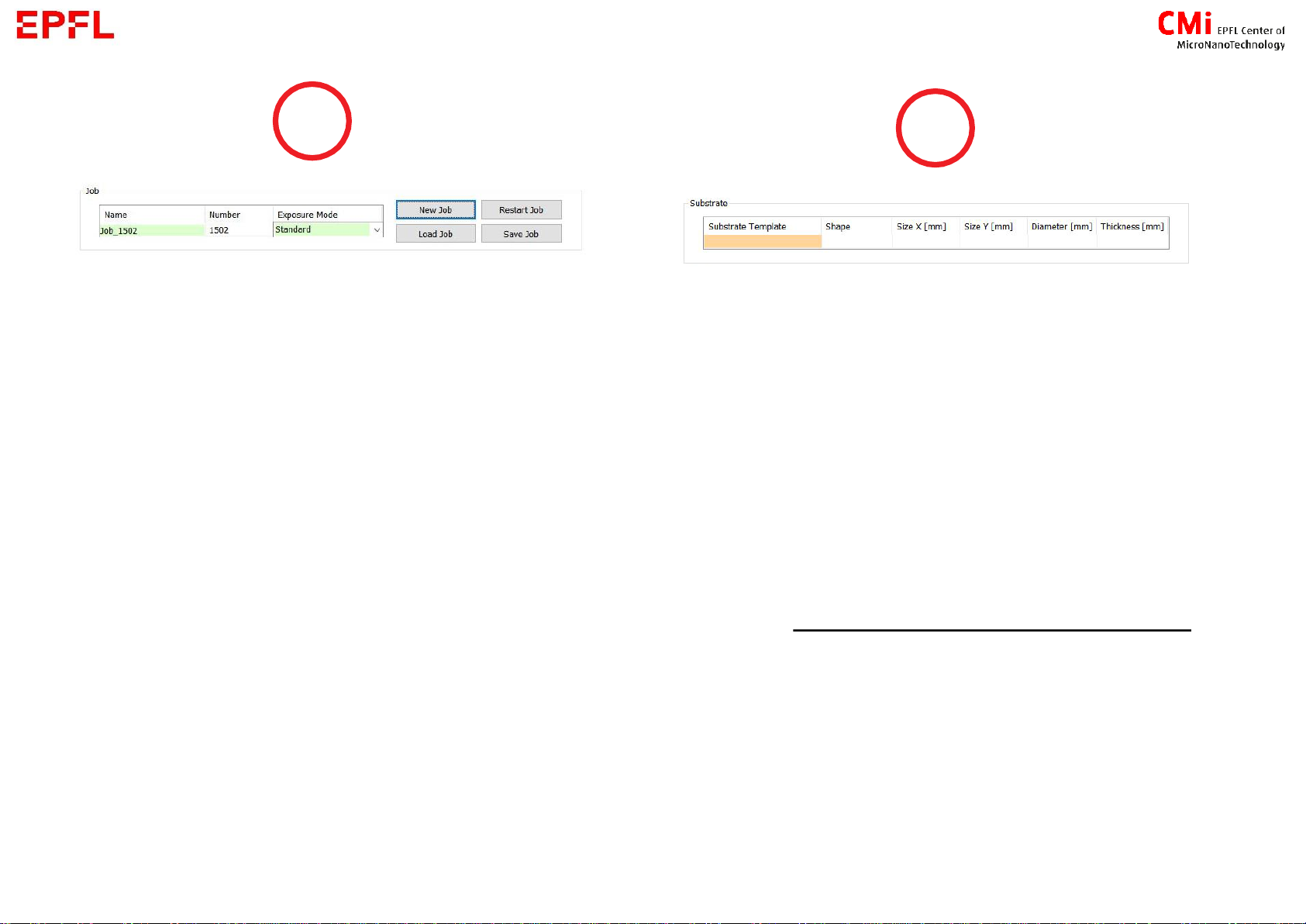
Create a new job or load one
→when done setting a job, you can save it
(please give it a specific name, jobs without
one will be deleted)
Chose the exposure mode :
1. Standard : Expose the design once
2. Series : Expose the design N times with
different parameters for dose and defoc
→how to determine optimal parameters for
your project
3. DrawMode : Use the camera to expose
designs (bitmap format) in specific location
4. Inspection : To inspect the loaded substrate
with the camera
Double click on the orange box to chose
your substrate :
▪Wafer X inch or Mask X inch (X = diameter [in])
▪Small : if your sample is smaller than 50x50mm
▪_Automatic X template : if you are not sure about the
dimensions of your substrate
→Thickness value is not important
7
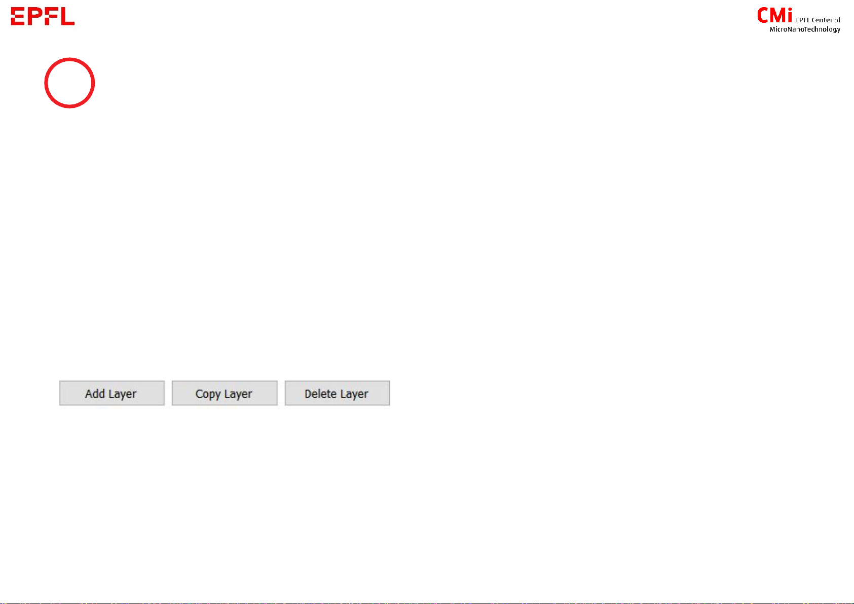
Job layers
→Each layer is determined by : design + laser
parameters for the exposition (Dose and focus are
set later in the process)
→Each lithography step of your process flow can be
represented by a layer (In this case save your job
and reload it [see slide 5] when performing further
steps)
→You can add, copy or delete layers
→It exist 2 types of layer :
- First Exposure = no alignment
-
Job parameters
Laser : choose between 375nm and 405nm
according to recommendation
Laser power : 100% (filter is used for Greyscale)
Design : Choose from the list of converted design
→See Chapter 2 to convert your design
Exposure bitmaps : to add extra bitmaps image to
be exposed in specific positions
Resist :
1 - LargeDefoc = to extend focus range
from [-10;10] to [-25;25] →used with 20 to
100um thick resist
HAR (High Aspect Ratio) : increase the depth of
focus →require higher dose
Large →for 100 to 300um thick resist
X-Large →for >300um thick resist
→Can be set only for non-FirstExposure layers
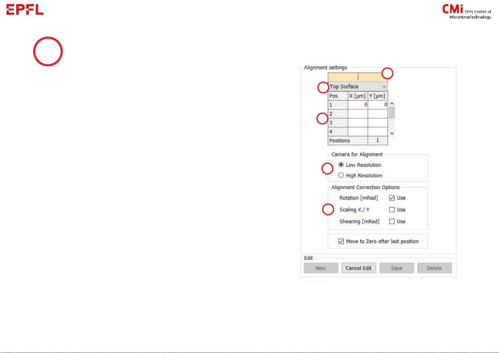
→Load an alignment setting or create one :
a) Name : to find the settings later in the list
b) Top or Back side alignment (see next slide for more
information about backside alignment)
c) Position of the marks : enter the coordinates of your
marks
d) Camera for alignment : the one used during the
procedure
e) Alignment Correction Options :
- Rotation : minimum 2marks
- Scaling and Shearing : minimum 3marks
8
Alignment Settings
→After creating/editing settings, save, and refresh the list if needed
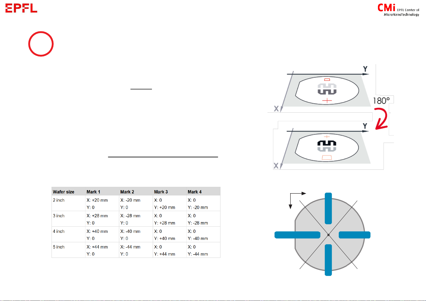
The coordinates on the MLA always refer to the substrate
side that is currently the upper surface (e.g. if an alignment
mark is exposed at the position [X: +20 mm], the alignment
mark will be at position [X: -20 mm] for the backside
alignment.
The alignment marks need to be in a specific area. See blue
zone on the image or layer 65 in the CMi layout template for
exact positions. Example of correct positions :
9
Alignment Settings –Information for backside alignment
Wafer 4 inch

10
1.C Expose
→When your job is ready, select the layer to be exposed and click on
→For wafer :
2. Place the guide
according to your
wafer size
3. Place and centre
the wafer against
the guide
4. Activate the
Vacuum
5. Remove the
guide, close the
door and follow
screen instructions
1. open the window

11
1.C Expose
→For small samples :
1. Open the window 2. Place your sample in the centre of the chuck (best to align it in X
and Y directions) 3. activate the vacuum 4. close the door →Follow screen instructions
→Next steps depend on your job :
1) Standard [s.12] 2) Standard with alignment [s.13] 3) Series [s.15]
You will need to determine the centre of your sample. Move
with the arrows or the target tool to go manually to the
centre of your sample (Target tool is always enable at
beginning, simply click on the substrate where you think is
the middle, you will be able to fine tune the position later)
Validate the position only when you are at the centre of
the substrate !

12
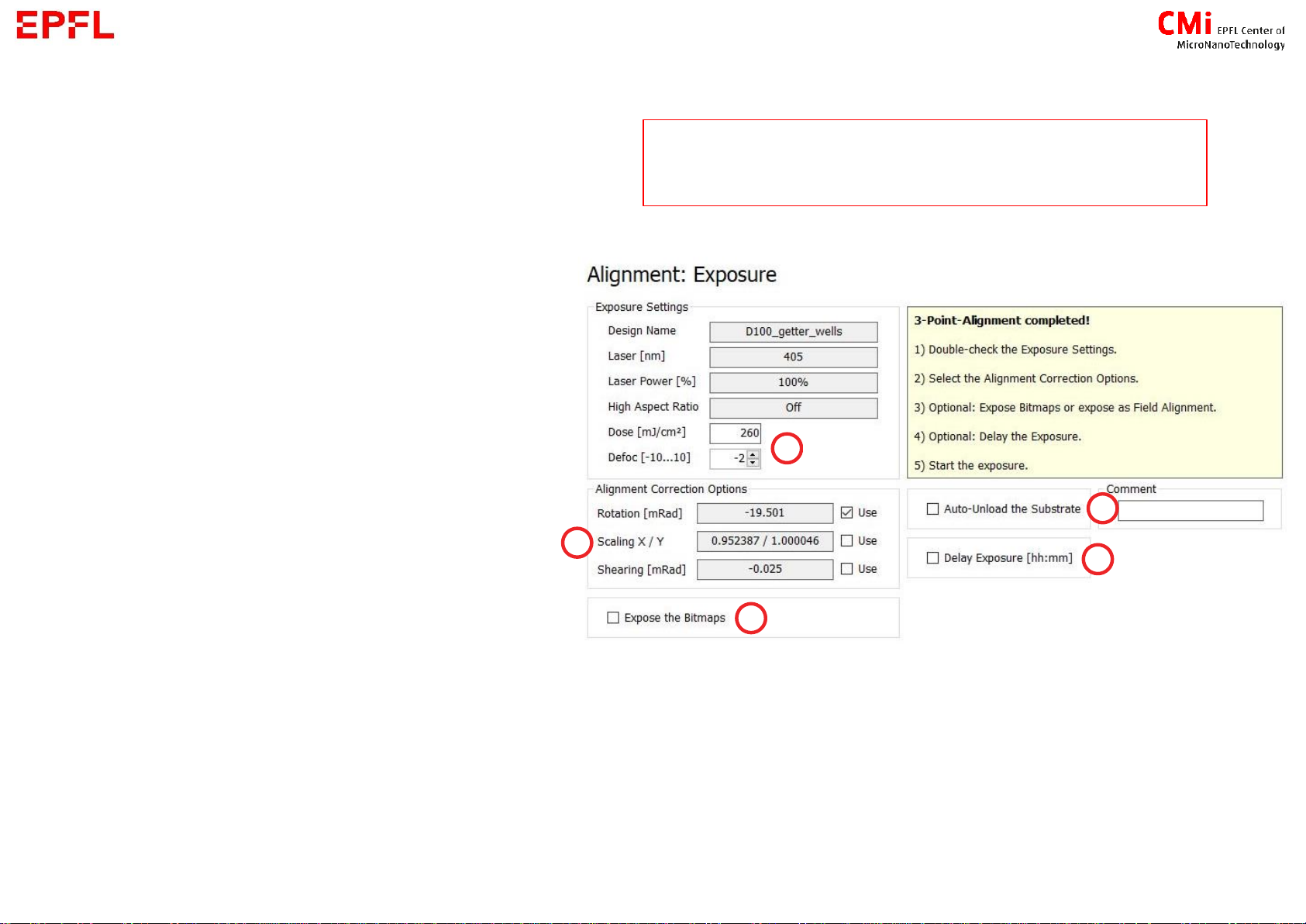
1) Standard
a) Set a dose and focus according to
the Resist Table (Desktop) or from
your own experience
b) The design can be tilted based on
the rotation of your substrate
measured by the machine
c) Enable the exposition of bitmaps
you set previously
d) Delay the exposure [hour:minutes]
e) Auto-unload the substrate if you
want to expose only one layer
Be aware that MLA-1 and MLA-2 have
different Resist Tables
13
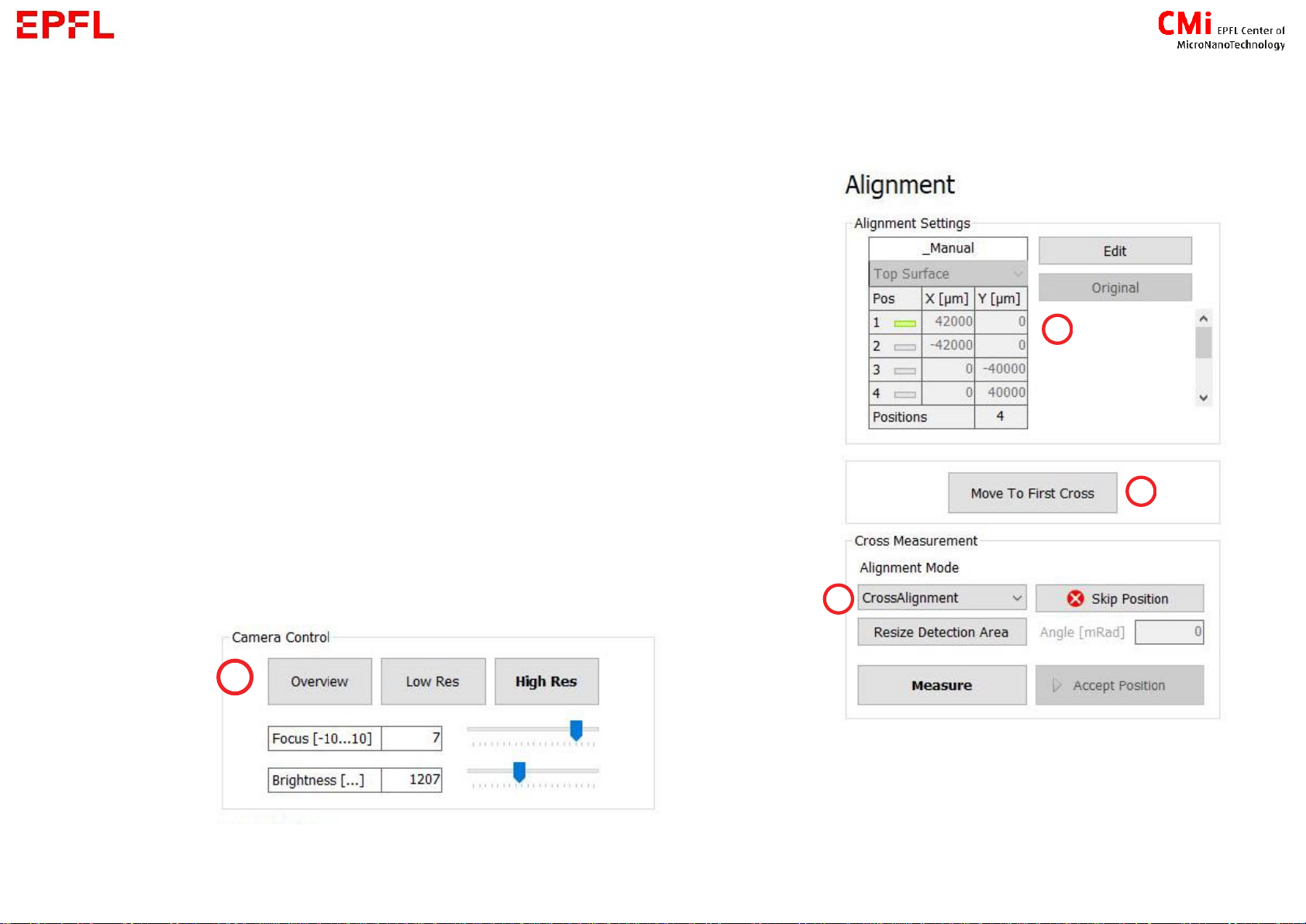
2) Standard with alignment
a) Control if alignment positions are correct and edit if needed
b) Click to start alignment procedure
c) Overview and Low Res camera →move to your mark
High Res →for the measurement
d) Chose measurement mode :
- Automatic : CrossAlignment or RectangleAlignment
- Manual : ManualAlignment

14
2) Standard with alignment
e) For automatic detection, please make sure the feature to
it, press on Resize/Maximize Detection Area and select a zone on
the camera window or slide the sides of the rectangle.
f) Measure:
-automatic detection of the feature
-manual selection of the position with the target tool
→Remeasure or Accept Position
→Repeat c-f for all the marks
15
2) Standard with alignment
g) Set a dose and focus according
to the Resist Table (Desktop) or
from your own experience
h) Define which correction based
on alignment you want to apply
i) Enable the exposition of
bitmaps you set previously
j) Delay the exposure
[hour:minutes]
k) Auto-unload the substrate if you
want to expose only one layer
Be aware that MLA-1 and MLA-2 have
different Resist Tables

16
3) Series
a) Choose parameters to test :
dose / focus / dose + focus
b) Define starting value, step and how
many lines (# of fields) should contain
the matrix
c) Distance between 2 dyes in the matrix
(stay orange if overlapping)
d) Label at the bottom left of each dye
containing Dose and Focus
e) Delay the exposure [hour:minutes]
f) Auto-unload the substrate if you
want to expose only one layer
17
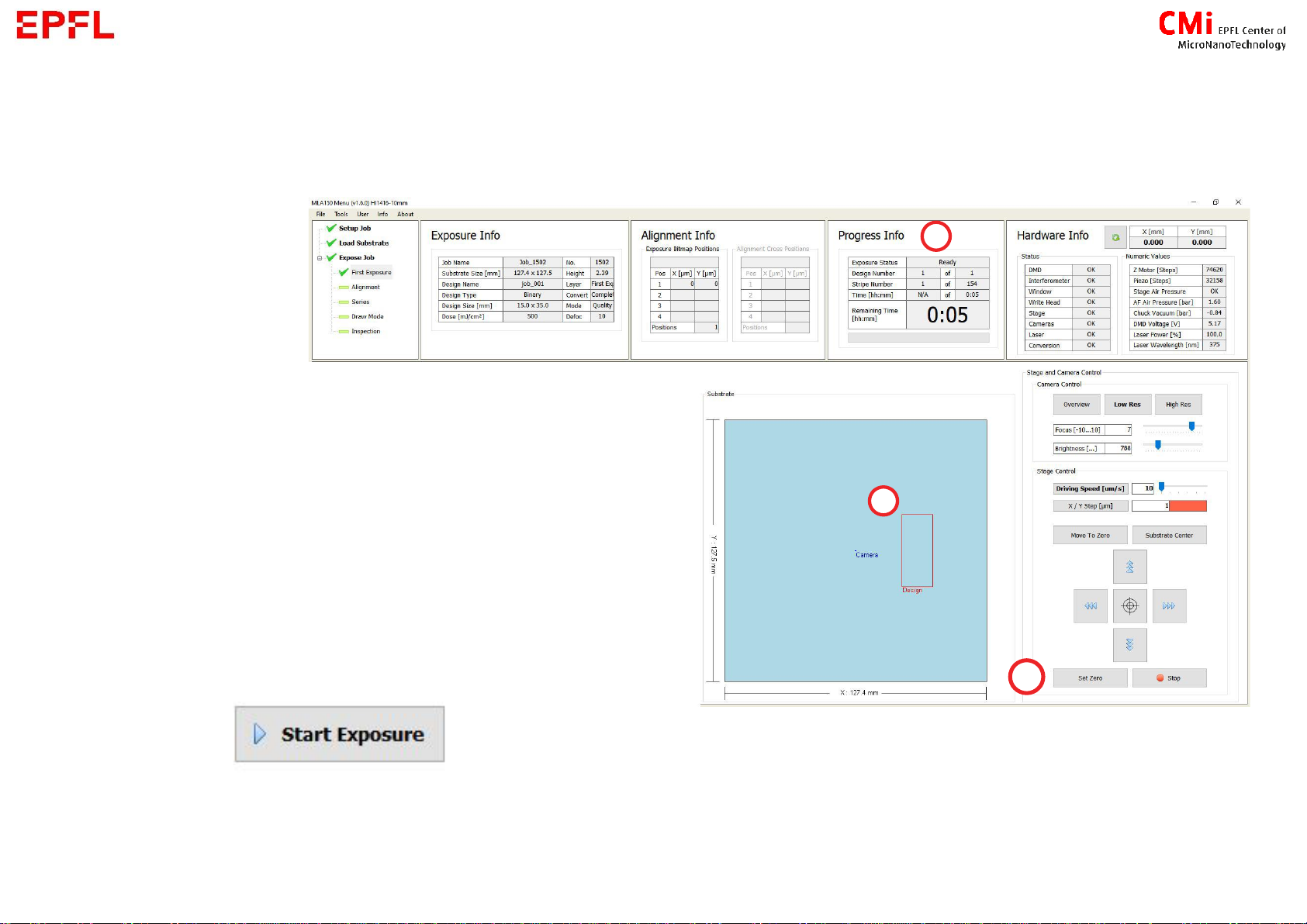
Exposition information and position
a) Estimated maximum time for exposition
b) Position of exposed design. Hold-click on its
side to move it on the substrate.
c) When using the camera to find the appropriate
position for exposition, press Set Zero at the
desired position for the design centre
→If all information on the screen looks correct,
press :
In case you have change the exposition position, an error message about not being in
the centre will appear. You can acknowledge it !
18
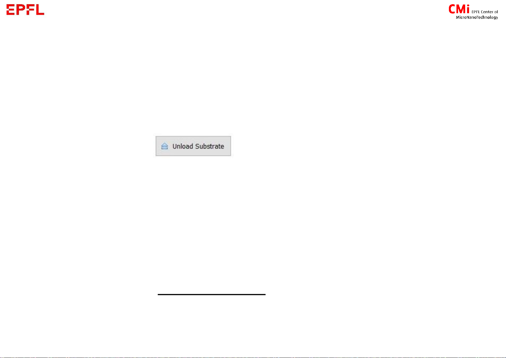
1.D End
If not automatically unloaded, your can restart your job in the main menu or expose a
second layer
If you are done, click
→When back to the main menu:
1) open the windows
2) deactivate the vacuum
3) get back your sample
4) close the windows
→Press New Job
→Go to the Zone PC to log out from the CAE

2. Design Conversion
20
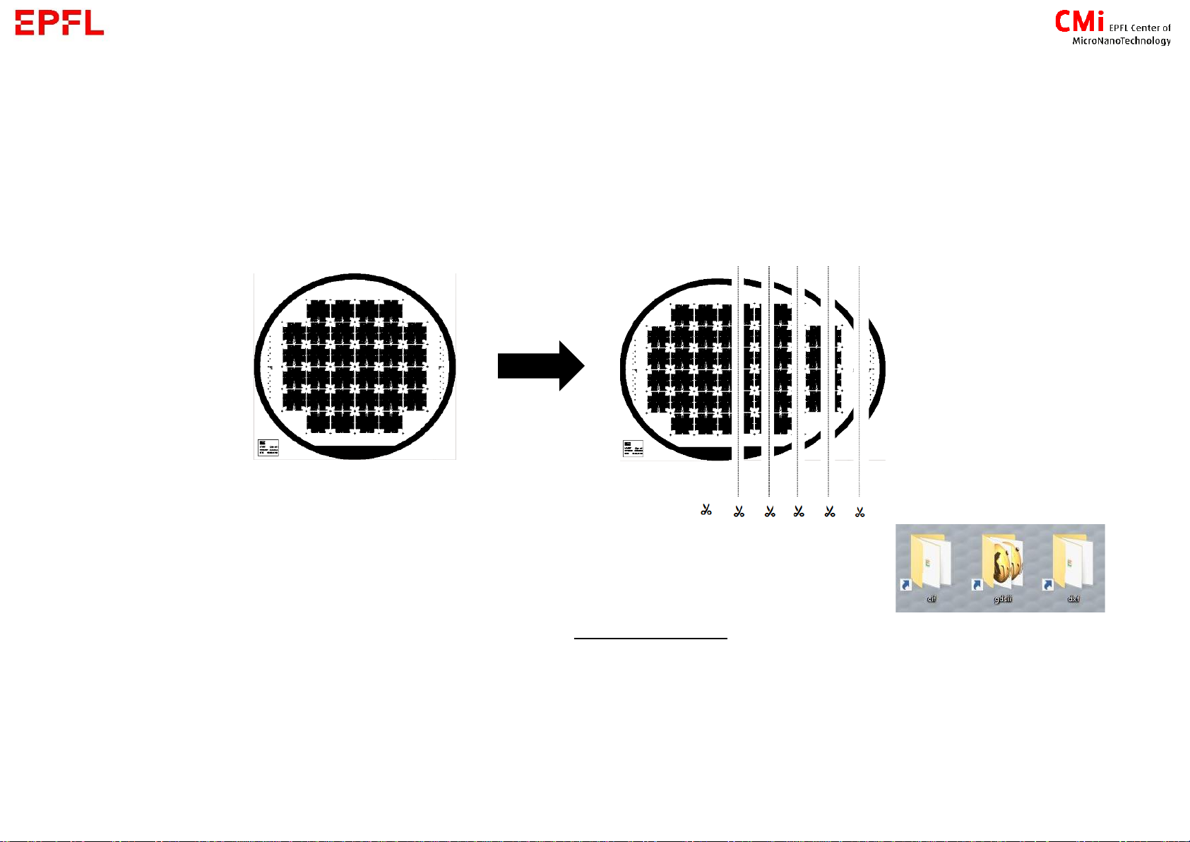
2. Convert
- Goal : convert your design into a series of stripes than can be exposed by the MLA150
1. Copy your design into the corresponding file extension folder
Allowed extension : .gds , .cif , .dxf (no capital letter)
Allowed character for file name
Popular Laboratory Equipment manuals by other brands


Agilent Technologies
Agilent Technologies InfinityLab LC Series user manual

Cannon
Cannon TE-3000 instruction & operation manual

BioLAB
BioLAB BIFL-204 Operation manual

Ocean Insight
Ocean Insight OCEANHDX RAMAN quick start guide

Qiagen
Qiagen PyroMark Q96 quick start guide

Sterlitech
Sterlitech 1812 Assembly & operation manual


