HEIDENHAIN UV 130D User manual

1/2014
Austauschanleitung
Replacing Instructions
Versorgungseinheit
UV 130
D
als Ersatz für UV 130
Power supply unit
UV 130
D
as Replacement for UV 130

2
Dieses Symbol zeigt Ihnen dass eine oder mehrere der folgenden Gefahren bestehen:
nGefahren für Werkstück
nGefahren für Spannmittel
nGefahren für Werkzeug
nGefahren für Maschine
nGefahren für Personen
Dieses Symbol zeigt Ihnen dass besondere Hinweise zu beachten sind.
Dieses Symbol zeigt Ihnen dass Sie detailliertere Beschreibungen in einer anderen
Dokumentation finden.
Bedeutung der verwendeten Symbole

3
Kom atibilität:
Die Versorgungseinheit UV 130
D ist bedingt anbau- und anschlusskompatibel!
Achtung!
Der Austausch darf nur durch eine Elektrofachkraft erfolgen!
Eigenschaft
UV 130
DUV 130
Lage der Stecker
X70 X71 X72 X69 X79 Frontseitig links Frontseitig rechts
Frontseitig links oben Frontseitig rechts oben
Zwischenkreisanschluss
Rechts unten Links unten
Lage der Anschlussklemme X31
Stecker X90 (Ausgang 24 V)
Vorhanden Nicht vorhanden
Nicht vorhanden Vorhanden
Stecker X74
X31 Versorgungsspannung für Umrichter (3x 400 V + 10 %)
X69 Versorgung für die Steuerung
X70 Hauptschütz
X71 Sicherheitsrelais Spindel (Impulssperre für die Spindel)
X72 Sicherheitsrelais Achsen (Impulssperre für alle Achsen)
X74 5 V-Stromversorgung
X79 Gerätebus
X89 Bremswiderstand
X90 24 V-Versorgung (z.B. für die Versorgung des Ausganges "Steuerung betriebsbereit")

4
Vorderseite Vorderseite
UV 130
DUV 130
Unterseite
X31
X89
Unterseite
X70
U
DC-LINK ON
X74
+ 5V
0V
X69 X79
READY UV
POWER RESET
POWER FAIL
U
DC-LINK
>>
I
DC-LINK
>>
I
LEAK.
>>
AC FAIL
NC RESET
Lage der Stecker und Klemmen
UVW

5
Passende Stromschienen liegen bei.
Die Klemme X74 muss nicht belegt werden.
8. Klappen Sie die Abdeckkappen für die Stromschienen herunter so dass diese einrasten.
9. Befestigen Sie die Abdeckung wieder auf der Vorderseite des Umrichtersystems.
10. Schalten Sie die Maschine ein.
11. Bestätigen Sie - falls vorhanden - die Meldung für das elektronische Typenschild.
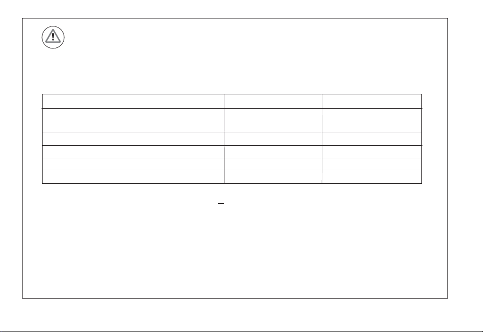
Arbeitsschritte:
1. Schalten Sie die Maschine aus und sichern Sie diese gegen Wiedereinschalten.
2.Beachten Sie die Entladezeit der Versorgungseinheit von 5 min. und stellen Sie mit einem
geeigneten Spannungsprüfgerät die Spannungsfreiheit am gesamten Umrichtersystem fest!
3.Entfernen Sie die Abdeckung von der Vorderseite des Umrichtersystems.
4.Bauen Sie die defekte Versorgungseinheit UV 130 aus.
5.Bauen Sie die neue Versorgungseinheit UV 130
D ein.
6.Stellen Sie alle Verbindungen wieder her.
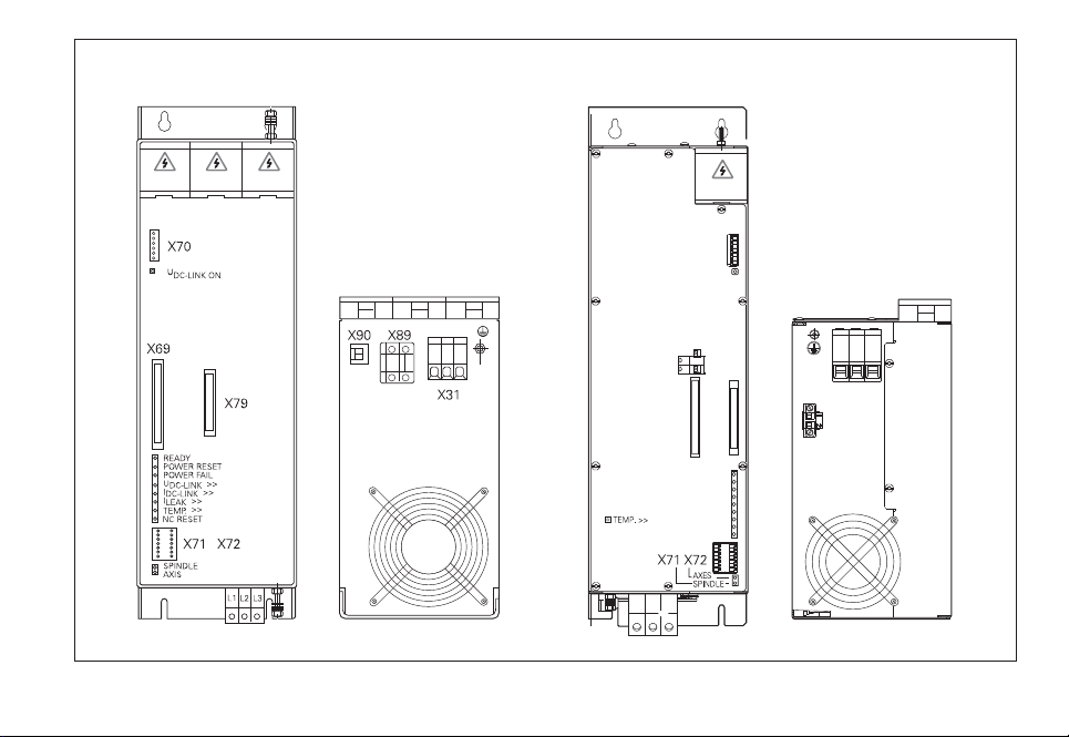
7. Falls der Stecker X90 beim UV 130 verdrahtet war klemmen Sie die Anschlüsse wie folgt um:
X90 Pin 1 (+) umklemmen auf X72 Pin 1
X90 Pin 2 (-) umklemmen auf X72 Pin 2

6
Prüfungen nach dem Einbau der neuen Versorgungseinheit
Gemäß DIN VDE 0113 Teil 1 / EN 60204-1 müssen nach dem Austausch einer Komponente
folgende Prüfungen durchgeführt werden:
DIN VDE 0113 Teil 1 / EN 60204-1
Hinweis!
Legen Sie die Austauschanleitung in der technischen Dokumentation der Maschine ab
und vermerken Sie die Änderungen!
1. Überprüfen Sie ob die elektrische Ausrüstung mit der technischen Dokumentation übereinstimmt.
2. Prüfen Sie ob eine durchgehende Verbindung des Schutzleitersystems besteht.
3. Führen Sie eine Funktionsprüfung durch.
Gefahr für Personen!

7
This symbol indicates that one or more of the following dangers exist
nDanger to the workpiece
nDanger to fixtures
nDanger to the tool
nDanger to the machine
nDanger to persons
This symbol indicates that important notes must be adhered to.
This symbol indicates that you can find detailed information in another documentation.
Meaning of the symbols used

8
Compatibility:
The UV 130
D power supply unit is partly compatible in its mounting dimensions and
electrical specifications!
Caution
The exchange may only be performed by an electrical specialist
Property UV 130
DUV 130
Position of the connectors
X70, X71, X72, X69, X79
on the front, left on the front, right
on the front, top left on the front, top right
DC link connection
bottom right bottom left
Position of the connecting terminal X31
Connector X90 (24 V output)
available not available
not available available
Connector X74
X31
Power supply for inverter (3x 400 V + 10 %)
X69
Power supply for the control
X70 Main contactor
X71
Safety relay for spindle (pulse inhibitor for the spindle)
X72
Axes safety relay (pulse inhibitor for all axes)
X74 5 V power supply
X79 Unit bus
X89 Braking resistor
X90 24 V supply (e.g. to power the output "Control is ready")

9
UV 130
DUV 130
X31
X89
X70
U
DC-LINK ON
X74
+ 5V
0V
X69 X79
READY UV
POWER RESET
POWER FAIL
U
DC-LINK
>>
I
DC-LINK
>>
I
LEAK.
>>
AC FAIL
NC RESET
Front Front
Bottom Bottom
Position of the connectors and terminals
UVW

10
Use the enclosed conductor bars.
The terminal X74 does not have be assigned.
8. Lower the cover caps for the conductor bars until they engage.
9. Mount the cover on the front of the inverter system.
10. Switch on the machine.
11. If present, confirm the message for the electronic ID label.
Work steps:
1. Switch off the machine and take precautions against restart.
2.Pay attention to the discharge period of the power supply unit of 5 min. and use a suitable
voltage test unit to ensure that the entire inverter system is not under voltage!
3.Remove the cover on the front of the inverter system.
4.Remove the defective UV 130 power supply unit.
5.Mount the new UV 130
D power supply unit.
6.Reestablish all connections.
7.
If the connector X90 of the UV 130 was connected, proceed as follows
Change connection of X90 / pin 1 (+) to X72 / pin 1
Change connection of X90 / pin 2 (-) to X72 / pin 2

11
Note
File the replacing instructions in the technical documentation of the machine
and record the changes!
Tests after mounting the new power supply unit
According to DIN VDE 0113, part 1 / EN 60204-1 the following must be checked after
a component has been exchanged
DIN VDE 0113, part 1 / EN 60204-1
Danger to persons!
1. Check whether the electrical equipment corresponds to the technical documentation.
2. Check whether the connections of the grounding conductor system are continuous.
3. Perform a functional test.

DR. JOHANNES HEIDENHAIN GmbH
Dr.-Johannes-Heidenhain-Straße 5
83301 Traunreut, Germany
{+49 8669 31-0
|+49 8669 5061
E-mail [email protected]
Techn cal support |+49 8669 32-1000
Measur ng systems {+49 8669 31-3104
E-mail [email protected]
TNC support {+49 8669 31-3101
E-mail [email protected]
NC programm ng {+49 8669 31-3103
E-mail [email protected]
PLC programm ng {+49 8669 31-3102
E-mail [email protected]
Lathe controls {+49 8669 31-3105
E-mail [email protected]
www.he denha n.de
664789-92 · Ver01 · 1/2014 · Printed in Germany · S
Table of contents
Languages:
Other HEIDENHAIN Power Supply manuals