HEINKEL-TOURIST 103 A-1 Instruction manual


Workshop Manual Heinkel Tourist 103 A-1 page 1
To all HEINKEL Dealers
This Manual is intended to assist you in carrying out all
maintenance and repair work in your HEINKEL workshop.
Detailed drawings make the text easy to understand so that no
motor fitter should have any difficulty in carrying out any
repairs quickly and rationally.
Correlation of the illustration references with the text is
simplified by figures. For example 10/2 : 10 is the number of
the illustration and the figure 2 after the oblique stroke refers to
the part number in the illustration in question.
All repairs particularly on the engine of the vehicle should only
be carried out with the proper special tools. For repairs never
use any but Original HEINKEL spare parts or Original
HEINKEL Exchange Parts as otherwise our part of the
Guarantee becomes invalid.
Our Customers' After-sale Service Department will always
welcome any hints and suggestions which you may care to give
us for the enlargement and improvement of this Manual.
ERNST HEINKEL AKTIENGESELSCHAFT
STUTTGART-ZUFFE HAUSE

Workshop Manual Heinkel Tourist 103 A-1 page 1
a
To all HEINKEL Owners
This Manual is intended to assist you in having carried out all
maintenance and repair work in your HEINKEL dealer's
workshop. Besides we believe that many of you are interested
in knowing more about your HEINKEL TOURIST motorscooter
than we can tell you in the Owner's Manual. Furthermore this
Manual might help you when travelling abroad especially
when travelling in countries where on account of importation
restrictions or for other reasons no HEINKEL workshops can
be found in case of trouble you might show this copiously
illustrated Manual for information to the workshop people and
thus save precious time and money.
We draw your attention to the fact that all repairs particularly
on the engine of the vehicle should always be carried out with
the proper special tools. For repairs never use any but
Original HEI KEL Spare Parts or
Original HEI KEL Exchange Parts,
as otherwise our part of the Guarantee becomes invalid.
Detailed drawings make the text of this Manual easy to
understand. Correlation of the illustration references with the
text is simplified by figures. For example 10/2 : 10 is the
number of the illustration and the figure 2 after the oblique
stroke refers to the part number in the illustration in question.
ERNST HEINKEL AKTIENGESELSCHAFT
STUTTGART-ZUFFE HAUSE

Workshop Manual Heinkel Tourist 103 A-1 page 2
Contents
Foreword . . . . . . . . . . . . . . . . . . . . . . . . . . . . .
1, 1a
Technical Data . . . . . . . . . . . . . . . . . . . . . . . . . . . .
3
Exchange Engine . . . . . . . . . . . . . . . . . . . . . . . . . . . 6
Special Tools . . . . . . . . . . . . . . . . . . . . . . . . . . . . 7
Miscellaneous . . . . . . . . . . . . . . . . . . . . . . . . . . . .
9
Dismantling and reassembling the engine . . . . . . . . . . . . . . . . .
9
Dismantling the Cylinder Head, Cylinder and Piston
. . . . . . . . . . . . .
11
Reassembling the Cylinder Head, Cylinder and Piston
. . . . . . . . . . . .
12
Adjusting the valves . . . . . . . . . . . . . . . . . . . . . . . . . 13
Dismantle, ream but and assemble connecting rod bush
. . . . . . . . . . .
14
Dismantle and assemble cylinder Head, grind in valves
. . . . . . . . . . .
15
Check Piston and Cylinder
. . . . . . . . . . . . . . . . . . . . . . .
17
Table of Measurements and Oversizes (Cylinder and Piston)
. . . . . . . . .
18
Dismantling the Clutch . . . . . . . . . . . . . . . . . . . . . . . .
19
Fitting the Clutch . . . . . . . . . . . . . . . . . . . . . . . . . .
21
Dismantling the Dynamo . . . . . . . . . . . . . . . . . . . . . . . .
23
Assembling the Dynamo . . . . . . . . . . . . . . . . . . . . . . . .
25
Adjusting the Ignition . . . . . . . . . . . . . . . . . . . . . . . . .
27
Measuring voltage and current on Dynamo and Governor Switch . . . . . . . .
28
Measuring Voltage on the Dynamo . . . . . . . . . . . . . . . . . . . 28
Measuring charging current . . . . . . . . . . . . . . . . . . . . . .
28
Dismantling the Swinging arm . . . . . . . . . . . . . . . . . . . . .
29
Fitting the Swinging Arm
. . . . . . . . . . . . . . . . . . . . . . . .
31
Table of Bolts . . . . . . . . . . . . . . . . . . . . . . . . . . . .
33
Tightening Torques for Bolts and uts . . . . . . . . . . . . . . . . . . 33
Dismantling Crankshaft and Bearing . . . . . . . . . . . . . . . . . . .
34
Fitting Crankshaft and Bearing . . . . . . . . . . . . . . . . . . . . .
35
Dismantling the Gears . . . . . . . . . . . . . . . . . . . . . . . . 37
Fitting the Gears . . . . . . . . . . . . . . . . . . . . . . . . . . 38
Removing, dismantling and refitting of Carburettor . . . . . . . . . . . . .
39
Removing, dismantling and refitting of BI G Carburettor
. . . . . . . . . . .
39
Removing, dismantling and refitting of PALLAS Carburettor
. . . . . . . . . .
41
Removing and Fitting the Front Fork
. . . . . . . . . . . . . . . . . . .
43
Disassembling and Fitting of the Front Fork . . . . . . . . . . . . . . . . 44
Removing and Fitting of Frame and Fork Ball Races . . . . . . . . . . . . .
44
Removing and Fitting of Front Wheel Hub
. . . . . . . . . . . . . . . . .
45
Removing and Fitting Brake Shoes . . . . . . . . . . . . . . . . . . .
45
Adjusting the Gear Shift Arrangement . . . . . . . . . . . . . . . . . .
46
Adjusting the Clutch . . . . . . . . . . . . . . . . . . . . . . . . .
46
Adjusting the Headlamp . . . . . . . . . . . . . . . . . . . . . . . .
47
Removing and Fitting of Frame
. . . . . . . . . . . . . . . . . . . . .
48
Power Curve . . . . . . . . . . . . . . . . . . . . . . . . . . . . 49
Speed Curve . . . . . . . . . . . . . . . . . . . . . . . . . . . .
49
Climbing Performance Curve . . . . . . . . . . . . . . . . . . . . . . 49
Fuel Consumption Curve . . . . . . . . . . . . . . . . . . . . . . .
49
Wiring Diagram . . . . . . . . . . . . . . . . . . . . . . . . . . .
50
Table of Loads . . . . . . . . . . . . . . . . . . . . . . . . . . .
51
Drawing of Assembly Jig for Scooter . . . . . . . . . . . . . . . . . .
52
Drawing of Assembly Jig for Scooter Engine
. . . . . . . . . . . . . . . .
53
Table for Service, Maintenance and Greasing . . . . . . . . . . . . . . . . .54

Workshop Manual Heinkel Tourist 103 A-1 page 3
Technical data of motorscooter »HEINKEL-TOURIST«, model 1 3 A-1
Engine
Engine model 407 A-1
Engine cycle Four-stroke
umber of cylinders 1
Arrangement of Cylinders Vertical
Bore 60 mm. Ø
Stroke 61.5 mm.
Swept Capacity 174 cc.
Clearance volume 27.5 cc.
Compression ratios 1:7.4
Output 9.2 h.p. at 5500 r.p.m.
Compression pressure 130 lbs per sq. inch. (When fuel valve is open and
the engine is warm)
Piston play 0.05–0.06 mm.
Diameter of gudgeon pin 18 mm. Ø DI 73121 (watch the identification colours)
+ 0.025 mm.
Bore of compression ring 18 mm. Ø + 0.040 mm.
Seating of crank assembly 2 × annular groove bearings 6305 C 3
Seating for clutch shaft 1 × annular groove bearings 6203 C 3
Valve arrangement Overhead valves (V-type) in fully enclosed light-metal
cylinder head
Inlet valve 0.15 mm.
Valve clearance Exhaust valve 0.20 mm. measured on cold engine
Inlet/Exhaust 18° after t.d.c.
Inlet/Inlet 17° after b.d.c.
Exhaust/Exhaust 18° before b.d.c.
Valve timing
Exhaust/Inlet 19° before t.d.c.
± 1° measured with
2mm valve clearance
Inlet 6.975 mm. Ø — , 1 mm.
Diameter of valve stems Exhaust 6.965 mm. Ø — 0,01 mm.
Inlet 7 mm. Ø + 0.028 mm.
Bores of valve guides Exhaust 7 mm. Ø
+ 0.013 mm.
Valve spring pressure 30.0 kg (valve open)
10.3 kg (valve closed)
Cooling Fan-cooling
Lubricating system Oil-bath centrifugal lubrication
Ignition
Type of ignition Starter/Generator unit "BOSCH" 12 volt coil ignition with
automatic timing, 12 volts, 90 watts
(AZ/DAQ 90/12/1700 + 0.2 R 2)
Spark timing Retarded ignition
0.6—0.8 mm. before t.d.c, using timing tool (404/W 10)
or 8°—10° before t.d.c. (when setting by means of the graduated
disc)
Advanced ignition
6.5—7 mm. before t.d.c. or 33°—35° before t.d.c.
(when setting with the governor fully open)
Gap between contact breaker points 0.35—0.45 mm.
Spark plug calorific value 225 *) today: BOSCH W5 AC or NGK B7 HS
or Champion L81C
Spark plug thread M 14 X 1.25
Spark gap 0.5—0.6 mm.
Carburettor
eedle type carburettor with
accelerating pump
Pallas Type 20/14 P Bing Type 1/20/46
Carburettor passage 20 mm. 20 mm.
Main jet 80(85) 85
Slow-running jet 25 35
eedle jet 2701 2.66
eedle setting 3 3
Jet needle, conical 15 x 1.95 Ø
number 3
Mixture screw 2½ x turns open 1½ turns open
adjust to best idling
Air filter "Knecht" micronic air filter
*) see pteng (www.pteng.de)

Workshop Manual Heinkel Tourist 103 A-1 page 4
Clutch
Clutch Oil-bath multiple-disc clutch
Operation of clutch By hand on left handlebar
Clutch spring pressure 60—70 kg.
Thickness of outer plate max. 5.0 mm. min. 4.0 mm.
Clutch adjustment 2—3 mm. on the clutch lever (on handlebars)
Gearbox
Gearbox Four-speed type
Method of engagement dogs
Power Transmission
Engine-Gearbox
Single enclosed chain, ⅜“ x ⅜“ (56 links endless) , fully enclosed and
oil-bath immersed.
Power transmission
Gearbox-Rear wheel
Single roller chain, ½“ x 5/16“ reinforced, (70 links endless), fully
enclosed and oil-bath immersed.
Reduction Engine-Gearbox 1.882:1
Gear reduction ratios 1st Gear 3,51 : 1
2nd Gear 2,07 : 1
3rd Gear 1.38 : 1
4th Gear 1 : 1
Solo With Sidecar
Reduction ratio Reduction ratio
Gearbox-Rear wheel 2.727:1 Gearbox-Rear wheel 3.10 :1
Chain Wheels Chain Wheels
Gearbox 11 teeth Gearbox 10 teeth
Rear wheel 30 teeth Rear wheel 31 teeth
Total reduction Total reduction
1st gear 18.05:1
2nd gear 10.60:1
3rd gear 7.10:1
4th gear 5.13:1
1st gear 20.50:1
2nd gear 12.02:1
3rd gear 8.06:1
4th gear 5.83:1
Chassis
Frame Torsion-free tubular steel frame
Engine suspension Rubber-Insulated 3-point-suspension
Front wheel suspension Telescopic form with hydraulic shock-absorber
Rear wheel suspension Fully-enclosed swinging arm, with telescopic, hydraulically damped
suspension unit
Offset of front axle 92 mm. (unchanging)
Caster action 18—20 mm.
Handlebar steering range 50 degrees to left and right-hand sides
Steering (vertical) angle 25°
Toe-in of sidecar wheel 18—20 mm.
(please respect any special stipulations of the sidecar manufacturers)
Camber of the machine Up to 4 degrees (inclining towards sidecar) (please respect any
special stipulations of sidecar manufacturers)
Handlebars Pressed-steel handlebars with built-in speedometer (calibrated
either in kilometers or in miles) and with twist -grip gear shift.
Brakes Mechanical internally-expanding brakes, drum 140 mm. diam,
width 25 mm.
Operation of brakes Hand-lever for front-wheel brake,
Foot-operated pedal for rear wheel
Wheels All interchangeable
Rims Flat-base rims s. 50X10"
Tyres 4.00 x 10“
Tyre pressure Front wheel Rear wheel Sidecar
driver only 18 psi 26 psi
driver and passenger 18 psi 29 psi
driver with sidecar passenger 22 psi 29 psi 22 psi
driver with pillion passenger
and sidecar passenger
22 psi 36 psi 29 psi

Workshop Manual Heinkel Tourist 103 A-1 page 5
imensions and Weights
Wheelbase 1375 mm.
Overall length 2085 mm. (without rear luggage carrier)
Maximum width 710 mm.
Maximum height 1000 mm.
Height of seat 735 mm.
Ground clearance approx. 145 mm.
Weight of vehicle, ready to be driven 150 kg.
Total weight admissible 350 kg.
Total weight admissible with sidecar 450 kg.
Fuel and lubricants
Fuel Use a proprietary brand
At least 82 octane (ROZ)
Fuel tank Holds 11.3 litres, of which approx. 1 litre forms a reserve.
Lubricant Use a proprietary brand, such as MOBILOIL SPECIAL,
for the whole year round. *)
Oil in the engine Approx. 1.5 litres (to the mark on the dipstick)
Oil in the swinging arm Approx. 0.15—0.20 litres
Fuel consumption, to DI 70030 standards 3 litres per 100 km
Maximum speed Approx. 92 km/h
*) Hint in year 2004: because of difficulties with the clutch, never use modern HD-oil or synthetic oil. Only use
classic oil for the engine. See pteng (www.pteng.de)
In the interests of technical development, we reserve the right to make modifications.
Workshop Manual Heinkel Tourist 103 A-1 page 6
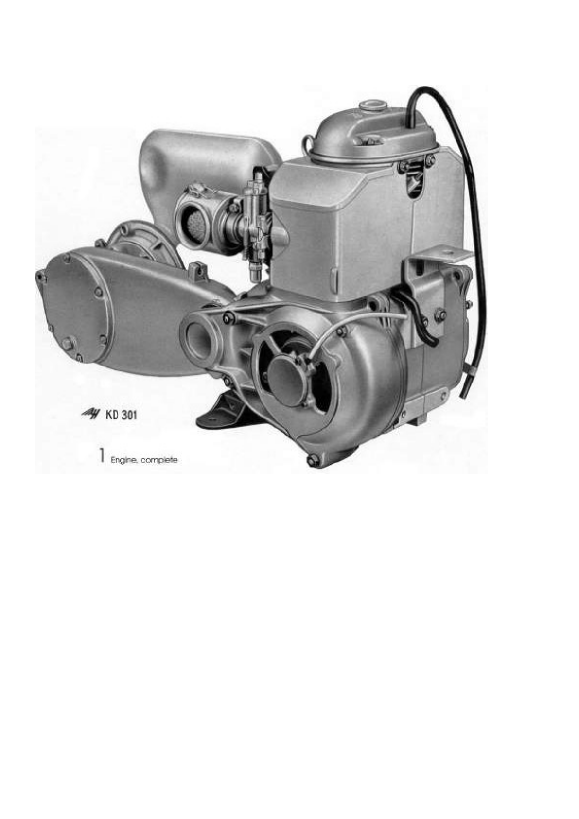
Engine » H E I N K E L - T O U R I ST «, model 4 7 A-1
Exchange engine:
Engines to be returned to the factory under the exchange scheme must be
as follows:
with swinging arm, complete, carburettor, exhaustmanifold, cooling baffles,
dip stick, magneto, complete, with spark plug, clutch lever with traction
spring and retainer plate, rear wheel hub with brake lever, all nuts, bolts
and discs, and the support for the mounting of the exhaust silencer,
without air filter, exhaust silencer, air outlet tube, guiding piece for the
Bowden cable operating the rear wheel brakes, support with sleeve for
Carburettor Bowden cable.
Note: Owing to import restrictions, import duties and for other reasons it
has not, unfortunately, been possible for the Factory to apply the German
Engine Exchange Scheme to foreign countries.

Workshop Manual Heinkel Tourist 103 A-1 page 7
Special Tools for »HEINKEL-TOURIST«
2 Special Tools
Key to illustration above:
o
.
Drawing o. Description
1 401/W 22 Extractor for driven pinion
2 408/W 14 Clutch retainer
3 401/W 20 Retainer plate for piston
4 401/W 19 Guide pin for rocker arm axle
5 407.201/W 5 Ball-bearing extractor, Type 6305
6 404/W 7 Extractor for starter dynamo
7 401/W 25 Clutch compressor
8 401/W 26 Gudgeon pin extractor
9 407/W 20 Piston ring clamp
10 407/W 21 Retainer for starter dynamo
11 401 /W 21 Snap ring opener
12 401/W 8 Assembly pliers for brake shoes
13 401/W 10 Assembly pliers for brake shoes
14 commercial type Meter for use with ignition timer
15 commercial type 5 mm. key for starter dynamo
16 407/W 30 Assembly sleeve for radial gasket
17 407/W 29 Assembly sleeve for sealing cap
18 commercial type Tension wrench (Torque-metering spanner) 0-6 mkg.
19 404/W 10 Ignition timer

Workshop Manual Heinkel Tourist 103 A-1 page 8
3 Special Tools
Key to illustration above:
o. Drawing o. Description
1 self-made Retainer for exhaust silencer
2 self-made Retainer for Engine
3 self-made Wooden punch for frame ball-races
4 commercial type Grease gun
5 407/W 37 Retainer for brake plate
6 self-made Extractor and refitter for connecting rod bushes
7 commercial type Reamer guide
8 commercial type Reamer for connecting rod bushes
9 commercial type Holder for hand milling cutter
10 commercial type Pilot for hand milling cutter
11 commercial type Milling cutter 29 mm diam. 77.5°
12 commercial type Milling cutter 32 mm diam. 45.0°
13 commercial type Milling cutter 32 mm diam. 30.0°
14 commercial type Cutter for adjusting valve seating
15 commercial type Guide for cutter for adjusting valve seating

Workshop Manual Heinkel Tourist 103 A-1 page 9
4 Scooter frame assembly jig
General ata
In order to facilitate repair work on the scooter frame we recommend
using an assembly jig (fig. 4, drawing on page 52) which can be
made by the dealer in his own workshop. The same applies to the
assembly jig for the engine (fig. 5, drawing on page 53).
When carrying out any major overhaul and/or fitting work on the
engine such an assembly jig and corresponding special tools should
in all cases be used.
Prior to carrying out repair work the vehicle should be cleaned most
thoroughly. After having been cleaned, the removed components
should be checked, for wear and tear, and, if necessary, be replaced.
Worn and damaged components should be exchanged for
Genuine HEI KEL Exchange Parts or
Genuine HEI KEL Spare Parts.
In order to fit correctly all moving parts, such as ball bearings,
shafts, axles, bushings, radial gaskets, pistons etc. should be lubri-
cated. To obviate leakage renew all gaskets, cleanse face surfaces
of the housings (housing halves) and seal with securing lacquer all
threads on parts that are in contact with oil.
All HEI KEL-Spares should be ordered by HEI KEL-Owners from
the HEI KEL-dealers and/or distributors, and not direct from the
HEI KEL factory. Overseas HEI KEL dealers order HEI KEL spares
from the distributors or from the importers. Only the importer may
order the spares direct from the HEI KEL factory in Western Ger-
many, or distributors direct, with the importer's authorization.
When ordering, the order should specify
1. name and address of ordering firm
2. mode of despatch requested
3. frame and engine number of vehicle involved
4. correct specification (nomenclature) of spare parts requested and
drawing number.
5. Quantity ordered.
ismantling and reassembling the engine
Raise the vehicle and, with the central stand set up, place it on
the jig. Place the two pegs of the cross-member into the two
middle holes provided on the gusset plate of the scooter frame,
fix frame tube on jig cross-member by means of screwing clamp,
fix central stand of scooter by means of clamping clip.
1. Remove spare wheel and spare wheel carrier. Raise the seat
cushion from the middle section. Take out the leads to the brak-
ing and licence plate light at the socket plug. Undo two hex.
bolts for the pipe clamps, open the side flap and remove the rear
coachwok.
2. Undo and disconnect battery cable. Remove the battery.
3. Undo and remove the leads which lead to the engine at the
governor and at the ignition coil. Remove the governor switch.
4. Close the fuel cock, disconnect the fuel line at the carburettor;
remove fuel tank. (Also remove rubber cushions beneath fuel
tank.)
5. Undo air filter locking screw and remove air filter, take off car-
burettor.
5 Assembly jig for scooter engine
Workshop Manual Heinkel Tourist 103 A-1 page 10
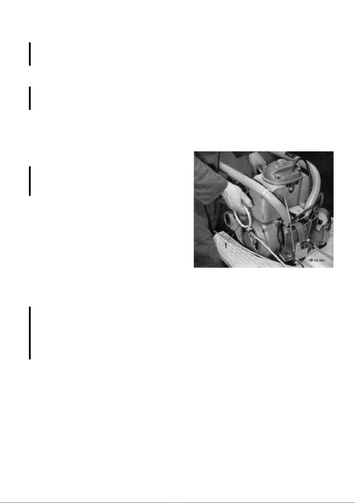
6 Lifting the engine out
6. Remove exhaust silencer and air outlet pipe.
Please note:
Avoid stress when fitting exhaust silencer as otherwise exhaust
manifold might break!
7. Undo four nuts on the rear wheel and remove the rear wheel.
Undo fixing bolts and nuts on the spring leg and remove spring
leg.
Please note:
When fitting the rear wheel, tighten wheel nuts at 6.0 mkg. Insert
upper fixing bolt of spring leg from inside!
8. Disengage rear wheel brake cable from the brake lever and
unscrew the brake cable set-screw from the support on the
swinging arm.
9. Disconnect the clutch control cable from the clutch lever. Unscrew
adjusting screw.
10. Undo cylinder screw on the shift lever and push lever off gear
selector. (Do not damage rubber ring!) Remove adjusting screw
for the clutch cable from the support on the clutch cover.
Please note:
When fitting the shift lever, the marks on the gear selector and
the shift lever have to correspond. Grease both rubber sleeves
on the switch cable by grease gun.
11. Undo the hex. nuts of the rubber elements for engine suspension
with a box spanner, push back hex. bolts (Box spanner SW 17.)
12. Loosen hex. bolt (SW 17) of clamp (right-hand side) (this makes
engine removal easier).
13. Lift the engine with swinging arm out to the rear, as shown on
fig. 6. It would be advantageous to use retaining jig 6/1
If further repair work is to be carried out on the engine, undo
two hex. nuts with box spanner (SW 15), remove internal toothed
disc and clamp for engine suspension. Fix engine on flange 5/2
of engine assembly jig by means of knurled screw 5/5 and
special nut 5/4. When engine in horizontal position, use piece
5/3 for support and fix fan wheel and armature by means of
retaining jig 5/1.
Reverse the procedure when reassembling.
Please note:
For connecting electric cables, proceed in accordance with wir-
ing diagram, page 50.
When fitting Genuine HEI KEL Exchange Engine, check oil level.
If necessary, fill in oil of well-known brand, such as e.g. Mobil
Oil Special.
Prior to operating, change Micronic filter insert.

Workshop Manual Heinkel Tourist 103 A-1 page 11
Engine
ismantling of cylinder head, cylinder and piston
Please note:
If you wish to carry out the above mentioned repair work, do
not remove the engine; just proceed as per page 9, "Dismantling
and Reassembling of Engine", paragraphs 1, 4, 5 and 6. (How-
ever, please bear in mind that this applies only to the above
repair work!):
1 . Undo the nuts on the cylinder head cover with box spanner
(SW 10), remove air-vent hose and cylinder head cover. Remove
cooling baffles, dismantle induction and exhaust manifolds.
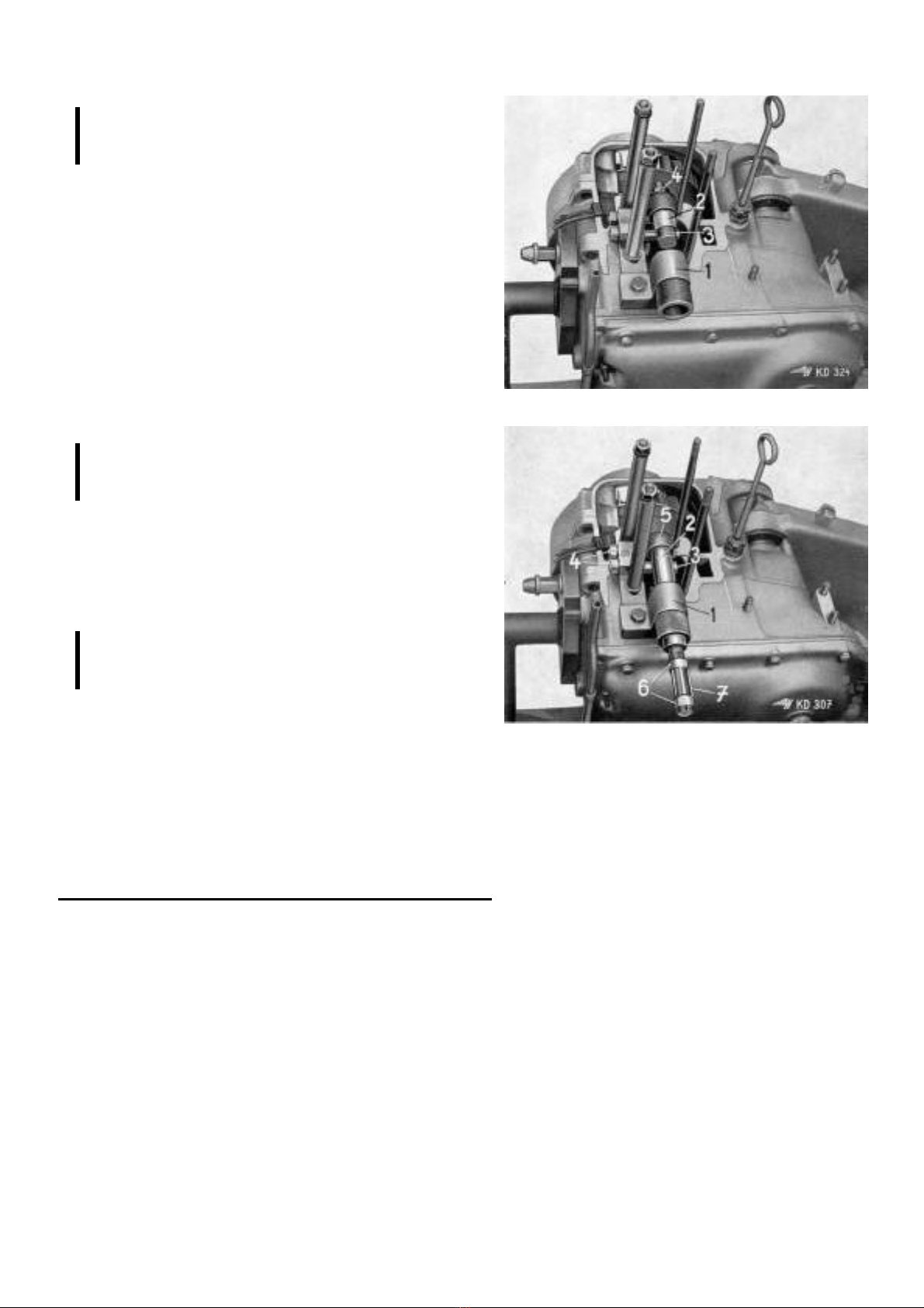
2. Unscrew and remove spark plug. Place piston at t.d.c. with valves
closed and loosen clamp nuts 7/1 and nuts for rocker arm shafts-
Cover push rod channel with clean rag. Undo two nuts (SW 10)
on rocker arm and slightly loosen the ball-shaped screw for
valve setting, so that the rocker arm shafts 7/2 can be pushed
out of their Journals with a pin without forcing.
Take off rockers 7/3 (and the spacing washers) and remove push
rods.
3. Using box spanner (SW 14), undo cylinder head fixing nuts 7/4
and take off cylinder head and cylinder. (Watch out for the soft-
iron washers, since these have to be used again when re-
assembling).
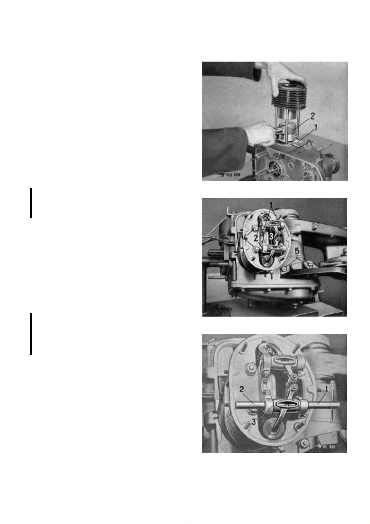
4. For better dismantling of the piston, use the forked retainer plate
(401/W 20) 8/1. Cover crank case with a piece of clean rag.
With a pair of pointed pliers, remove both wire snap rings from
the piston. Push out the piston gudgeon pin with gudgeon pin
extractor (401/W 26) 8/2 and remove piston.
Please note:
To avoid bending the connecting rod, on no account knock the
gudgeon pin out.
5. To strip the engine completely, undo nuts 7/5 and take off the
bracket.
7 Cylinder head with rocker arms
8 Dismantling the piston
Workshop Manual Heinkel Tourist 103 A-1 page 12
Reassembling piston, cylinder and cylinder head
9 Fitting the cylinder
10 Cylinder head with rocker arms
1 . Tighten tie rod for cylinder (3 mkg). To obtain safe sealing, wipe
tie rod on crank case with sealing lacquer.
2. Lay on to the crankcase the cylinder foot gasket (dry) and the
forked retaining piece (401/W 20) 9/1.
3. Fit the wire snap ring for the piston gudgeon pin in the piston.
Place the piston on connecting rod, insert the gudgeon pin into
piston and connecting rod bush as far as the wire snap ring,
holding the piston tightly with the left hand.
Cover crank case with a clean rag.
4. Insert the wire snap ring with a pair of pointed pliers. Make sure,
by twisting them, that the snap rings are properly seated.
5. Oil the working surfaces of the cylinder and also the piston.
Twist the piston rings, so that the gaps are not all facing in the
same direction.
6. Using the piston ring tightener (407/W 20) 9/2, squeeze the
piston rings together, fit the cylinder and lower carefully over
the piston. Remove piston ring tightener and forked retaining
piece (401/W 20).
Please note:
When using oversize cylinder and piston, the corresponding
measurements will be found listed on Genuine HEI KEL Ex-
change Cylinders. (See Page 18.)
7. Lay on cylinder head gasket (dry) and fit cylinder head. Lay on
washers 12/3 and wipe stay bolts with sealing lacquer. Using the
tension wrench, secure cylinder head by alternately tightening
diagonally-opposite bolts. (3 mkg). Once nuts 10/4 have been
tightened, seal with sealing lacquer.
8. Move crankshaft by rotating fan wheel and set piston at its top
dead center. Fit push rods and make sure that they are all set
at the same height. Fit rocker arms 10/3. To center rocker arms,
insert guide pin (401/W 19) 11/1 into bearing blocks and rocker
arms. If there should happen to be a relatively large lateral play
between rocker arm and bearing blocks, eliminate it by fitting
spacing shims, drawing number 408.300-014 (0.4 mm.), 408
300-015 (0.3 mm.), 408.300-016 (0.2 mm.).
Please note:
If a lateral play of rocker arms of up to 0.4 mm. is found, those
spacing shims are to be inserted on the pressure side (i.e. on the
side opposite to the push rods). If said play exceeds 0.4 mm.,
those spacing shims are to be inserted on both sides of the
rocker arm.
9. Fit shaft 11/2, tighten clamping screws 10/1 for rocker arm
shafts.
10. Adjust the valves (see page 13).
11. Screw in sparking plug. Fit induction and exhaust manifolds and
gaskets.
12. Lay on cylinder head cover gasket and fit cylinder head cover.
Fit cooling baffles and air outlet hose.
13. For further assembly, reverse the procedure as outlined, under
"Dismantling the Engine - Reassembling the Engine", page 9,
paragraphs 6, 5,4 and 1.
11 Fitting rocker arm shafts

Workshop Manual Heinkel Tourist 103 A-1 page 13
12 Adjusting the valves
Adjusting the valves
Please note:
Remove spare wheel and spare wheel carrier. Raise seat
cushion on middle section of rear cowling. Disconnect at plug the
cables for braking and rear licence plate light.
Undo two hex. nuts for pipe clamp. Remove rear cowling.
The valves should only be adjusted while the engine is cold.
1. Undo the nuts on cylinder head cover by using box spanner
(SW 10). Remove air-outlet hose and cylinder head cover.
2. Set piston at top dead center position. Both valves must be
closed.
3. Adjust the valves. (See fig. 12).
The valve tappet clearances are:
Inlet valve 12/1 0.15 mm.
Exhaust valve 12/2 0.20 mm.
4. Once adjusted, lock the setscrews with nuts.
5. For assembly, the reverse procedure is to be applied.
Workshop Manual Heinkel Tourist 103 A-1 page 14
Removing and fitting connecting rod bush, reaming out the bush
13 Inserting connecting rod bush
14 Centering connecting rod bush
Please note:
Proceed as outlined on page 11, "dismantling cylinder head,
cylinder and piston". Cover crankcase with clean rag.
1. Place and fix retaining jig with guide bush 13/1 on crankcase.
2. Turn both eccentric pins 14/3 on jig against connecting rod and
tighten nuts 14/4.
3. Place extractor with spacing pipe. By using two fork spanners
(SW 17), screw on nut and extract bush.
4. Mark lubrication hole on new bush. Drill lubrication hole with
twist drill 4.5 mm. + 0.5 mm. diam. (at an angle of 90 degrees to
bore of connecting rod bush.) Remove burr from inside and
outside of bush.
5. Place thus prepared bush on guide pin 13/3.
6. Center bush on top end of connecting rod. Put on guide pin of
guide jig and fit nut 13/4.
Insert bush 13/2 by screwing on nut, using two fork spanners
(SW 17).
Please note:
Lubrication holes of bush and top end of connecting rod must
correspond. Check alignment by using wire or needle.
7. Remove retaining jig with guide bush, undo nuts and turn both
eccentric pins away from connecting rod.
8. Center connecting rod 14/5 by using conical part 14/2 of the
reamer.
9. Turn both eccentric pins on jig against connecting rod and
tighten nuts.
Please note:
Prior to tightening, make sure by feel that the connecting rod
has not been tilted.
10. Loosen both adjusting nuts (SW 16) 14/6 on the reamer. Adjust
the cutters 14/7 to required diameter and then tighten adjusting
nuts again.
11. Insert reamer into connecting rod bush and slowly but conti-
nuously ream out the bush, constantly pressing forward. (Use
tap wrench or spanner.)
Permissible tolerances
Colour marks Ø hole for piston piston connecting
mm gudgeon gudgeon rod bush
White 18 + 0.003 0
+ 0.0005 - 0.0025 + 0.0425
Black 18 + 0.0005 - 0,0025 + 0.0275
- 0.002 - 0.005 + 0.0450

Workshop Manual Heinkel Tourist 103 A-1 page 15
ismantle and assemble cylinder head, grind in valves
15 Dismantling cylinder head
16 Hand-milling valve seats
Please note:
Proceed first as per page 11, "Dismantling the Cylinder head,
cylinder and piston, paragraphs 1, 2 and 3 (without removing
cylinder).
1. Place cylinder head onto jig (see fig. 15). Push lever and thus
compress valve springs, remove the conical valve cotters. Re-
move upper and lower spring plates, also remove external and
internal valve springs.
2. Clean cylinder head and remove oil carbon deposits.
3. Place cylinder head onto jig (see fig. 16) and fix by means of
retaining bolt 16/5.
4. Using a hand-milling cutter 16/4 mill inserted valve seats. Use
guide pin 7 mm. Ø + 0,013 mm.
+ 0,028 mm.
a) mill the channel, using cutter 29 mm. Ø. 77.5° 16/2.
b) mill the inserted valve seat, using cutter 32 mm. Ø
45.0°, 16/3.
c) mill the valve-bearing section of the inserted valve seat,
using cutter 32 mm. Ø, 30.0°, 16/1.
Inserted valve seats can also be milled by means of the
"HU GER"-Milling Tool for Inserted Valve Seats.
5. Place cylinder head 17/2 onto jig 17/1 and fix.
6. Firmly insert guide pin 17/3, using no lubricant, into the cleaned
valve guide.
7. Using hand-milling cutter, 29 mm. Ø, 77,5°, 16/2, mill the
channel.
8. Place on guide pin 17/3 the Milling Tool for Inserted Valve Seats
(sightly lubricate the top section of guide pin before). Loosen
fixing screw 17/5, while maintaining in position the Milling Tool
to prevent the cutter tip 17/6 damaging the valve seat.
9. Using fork spanner (SW 7), loosen lock nut 17/7 and adjust the
Rapid-Action Regulator 17/8 so that the cutter tip is positioned
in the middle of the valve seat.
10. Tighten set-screw 17/5.
11. Turn rapid-action regulator 17/8 anti-clockwise until cutter tip
17/6 is positioned at approx. 1 mm distance from the internal
edge of the valve seat.
12. Tighten lock nut 17/7.
13. Maintain annular support 17/9 in position while turning the crank
17/4 in direction indicated by arrow in fig. 17 until all of the
valve-bearing section is being milled until the cutter will run idle.
Please note:
If by the above procedure the valve seat has not been smoothly
milled (smooth surface!), proceed as follows:
14.Loosen lock nut 17/7, turn anti-clockwise rapid-action regulator
17/8 so that the cutter tip is positioned at approx. 1 mm. distance
from the internal edge of the valve seat. Tighten lock nut.
15. Loosen knurled screw 17/10 and turn milling regulator 17/11 to
the left (as indicated by arrow on fig. 17) by one line mark.
Tighten knurled screw again.
Please note:
1 line mark of the calibration about equals 0.1 mm.
16. Proceed as outlined under paragraph 13 above.
17. As after carrying out the above procedure the valve seat has
been milled smoothly (smooth surface!), proceed to finish-mill.
For this purpose, leave milling operator in same position. Only
operate rapid-action regulator 17/7 and 17/8 (see paragraph 14)
and repeat procedure as outlined in paragraph 13.
17 Milling valve seats, using special milling tool

Workshop Manual Heinkel Tourist 103 A-1 page 16
18 Measering spring pre-tension
18.Remove Milling Tool for Inserted Valve Seats.
19. Using hand-milling tool 32 mm Ø 30.0° 16/1, mill the valve-
bearing section of the valve seat. Remove guide pin.
Please note:
Widths of the valve-bearing sections of the valve seats
Inlet valve 1.1-1.2 mm
Exhaust valve 1.5 mm
20. Using a fine-grade grinding paste, grind the valves until all of
the bearing sections of valves and valve seats (on cylinder head
and valves) show a uniformly grey shine without any bright
grooves.
21. After grinding, clean valves and cylinder head.
22. Check that valve-seats have been thoroughly finished by using
engineers' marking blue.
23. Insert valves in cylinder head. Using depthmeter 18/1, measure
distance between top surface of the valve stem 18/2 and the
milled surface 18/3. (Support of lower spring plate.)
Please note:
This distance - for pre-tension of the spring - has to be:
for inlet valve 31.0-31.8 mm.
for exhaust valve 31.5-32.3 mm.
24. Compensate possible tolerances by using spacing discs (shims),
drawing number 404.300-005 (0.2 mm), 404.300-006 (0.5 mm.),
404.300-007 (1.0 mm.). Those spacing shims are to be placed
beneath the lower spring plate.
25. lnsert valves and place cylinder head onto jig (see fig. 15).
26. Lay on lower spring plate (if necessary, also lay on spacing
shims), internal and external valve springs and the top spring
plate. Compress lever of jig and thus compress valve springs;
insert conical valve cotters.
Please note:
The external valve spring, when in released position, has a total
length of 30.5 mm. Under 6.9 kg. pressure its length has to be
27.0 mm., under 20.0 kg. pressure 20.3 mm.
The internal valve spring, when in released position, has a total
length of 26.5 mm.. Under 3.4 kg. pressure its length has to be
23.0 mm., under 10.0 kg. pressure 16.3 mm.
Having fitted the valves, it is recommended to apply a few tap
hammer strokes on the end of the valve stem, using a plastic or a
rubber hammer, thus smoothening the valve seat sections and
obtaining perfect seating.
It is recommended, besides, to pour some petrol into the valve
ports to ascertain, by having a look at the bottom side of the
cylinder head, that the valves are a perfect fit.
Use an Exchange Cylinder Head if valve guides are so worn as
to exceed 7 mm. Ø + 0.013 mm.
+ 0.028 mm.
and/or if valve seat rings are very worn.
27. For further assembly, reverse the procedure as explained under
"Reassembling the Cylinder Head, Cylinder and Piston",
page 12, paragraphs 7, 8 etc.
Workshop Manual Heinkel Tourist 103 A-1 page 17
Check piston and cylinder
19 Testing the height play
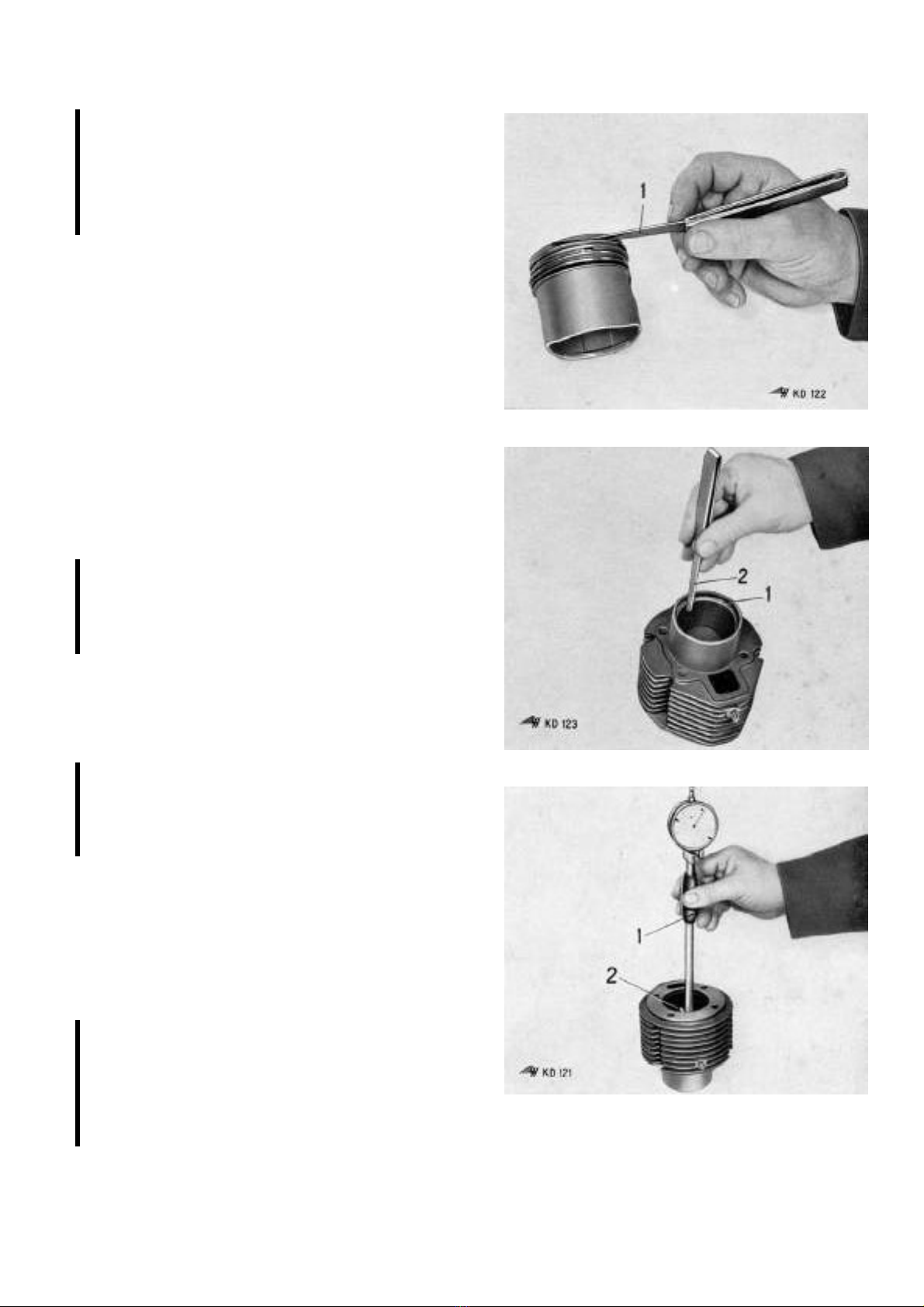
20 Testing the gap
Please note:
Proceed as explained on page 11, "Dismantling Cylinder Head,
Cylinder and Piston".
Cover the crankcase with a clean rag.
When refitting a used piston, remove all traces of oil carbon from
the piston head and the cylinder, take care that the piston is
fitted in the same direction as before (i.e. front to front).
1. Check piston (i.e. surface of contact) for grooves, traces of
piston seizures, worn spots (light grey surface!); check piston
rings for burns.
2. Using a feeler gauge 19/1, check the height play of the piston
rings, the permissible tolerance between the piston ring and the
ring groove being:
Ring Groove Piston Ring Minimum Maximum
I Compression ring (chromium) 0.060 mm. 0.090 mm.
II Compression ring 0.035 mm. 0.070 mm.
III Oil scraper ring 0.025 mm. 0.060 mm.
3. To check piston rings for gap, singly place one ring 20/1 at a
time in the foot of the cylinder and press flat with the skirt of the
piston.
Check gap of each individual ring by using feeler gauge 20/2.
Said play is not to exceed 0.40 mm.
Please note:
If the wear of the cylinder bore (ovality!) still lies within per-
missible tolerances (0.10 mm.), new piston rings may be fitted to
the piston. If not, the cylinder and the piston have to be ex-
changed.
4. By using a commercial-type cleaning tool or a section of the
piston ring, thoroughly and cautiously clean the ring grooves;
the grooves are, however, not to be enlarged thereby.
5. Fit the piston rings, taking care that the manufacturers' markings
are turned towards the piston head. The rings must be easily
turnable in their grooves.
Please note:
If fitting a new piston and gudgeon, take care that the colour
markings coincide. (See page 14). Those coloured dots are to be
found a) on the inside of the gudgeon pin boss on the piston,
b) on the end face of the gudgeon pin.
6. Clean the cylinder, remove all traces of oil carbon.
7. Check cylinder bore for grooves and spots of seizure.
8. Assess exact amount of wear on the cylinder; Insert cylinder
meter 21/1 in the bore of the cylinder, so that the feeler and the
guide pin 21/2 slide on the bearing surfaces of the cylinder.
Measure the cylinder bearing surface at at least 3 different spots:
at top dead centre, in the middle, at approx. 10 mm. from the
foot of the cylinder.
Please note:
The internal measuring gauge is to be adjusted, prior to its
application, to the "ORIGI AL" diameter, this adjustment being
carried out with the aid of a gauge ring or a micrometer.
(See Table of Original and Oversize groups on page 18). Should
the wear exceed the adjusted ORIGI AL size by 0.15 mm. or
more, the cylinder and the piston have to be exchanged.
21 Measuring the cylinder

Workshop Manual Heinkel Tourist 103 A-1 page 18
Please note:
Size groups are marked on the cylinders of new HEI KEL ve-
hicles, these marks are to be found opposite to the push rod
channel.
Size groups of new vehicles are marked opposite to the push rod
channel, size groups of oversize cylinders on the left- and/or
right-hand side of the cylinder top.
9. For further assembly proceed as explained under "Reassembl-
ing of Piston, Cylinder and Cylinder Head", page 12, para-
graphs 1-12.
Table for original and oversize groups
Cylinder Piston
ew vehicles Oversize Size Groups Tolerance
normal Y X W
0
0 - 0.010 59.94 Ø
0
1 + 0.010 59.95 Ø
+ 0.010
2 + 0.020 59.96 Ø
+ 0.020
60.0 Ø
3 + 0.030 59.97 Ø
0
0 - 0.010 60.04 Ø
0
1 + 0.010 60.05 Ø
+ 0.010
2 + 0.020 60.06 Ø
+ 0.020
60.1 Ø
3 + 0.030 60.07 Ø
0
0 - 0.010 60.44 Ø
0
1 + 0.010 60.45 Ø
+ 0.010
2 + 0.020 60.46 Ø
+ 0.020
60.5 Ø
3 + 0.030 60.47 Ø
0
0 - 0.010 60.94 Ø
0
1 + 0.010 60.95 Ø
+ 0.010
2 + 0.020 60.96 Ø
+ 0.020
61.0 Ø
3 + 0.030 60.97 Ø
Other manuals for 103 A-1
1


