Heinrichs ES Quick start guide
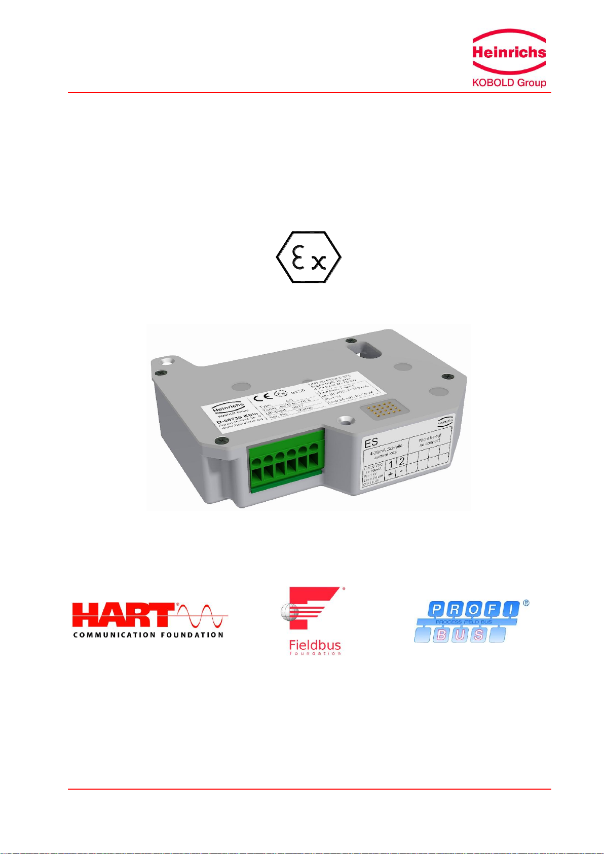
Ex-Supplementary manual ES
Page 1 of 8
Installation Notes for hazardous locations
These operating instructions are an addition to the operating manuals
BGN, BGF, TSK, BA, DWF with transmitter type ES, ES-PPA and ES-FF.
Please read the instructions carefully and store them in a safe place.
magneto-electric transmitter
ES
ES-PPA
ES-FF

Page 2 of 8
Ex-Supplementary manual ES
Table of Contents
1. INTRODUCTION...................................................................................................3
I. Shipping and storage; product inspection.........................................................................................3
II. Warranty ...........................................................................................................................................3
III. Application domain of the operating manual.....................................................................................3
IV. Measures to be taken before sending your device to the manufacturer for repair ...........................3
2. STEPS PRIOR TO OPERATION..........................................................................4
2.1 Installation, mounting, commissioning and maintenance .................................................................4
2.2 Hazard warnings...............................................................................................................................4
2.2.1 Danger........................................................................................................................................ 4
2.2.2 Warning...................................................................................................................................... 4
2.2.3 Caution ....................................................................................................................................... 5
2.2.4 Note............................................................................................................................................ 5
2.3 Proper use of the device...................................................................................................................5
3. IDENTIFICATION..................................................................................................5
3.1 Version / Date ...................................................................................................................................5
4. GENERAL INFORMATION ABOUT EXPLOSION PROTECTION .......................6
5. SCOPE OF APPLICATION...................................................................................7
6. MODE OF OPERATION AND SYSTEM LAYOUT................................................7
6.1 Measuring principle...........................................................................................................................7
7. ELECTRICAL CONNECTION...............................................................................7
7.1 ES type..............................................................................................................................................7
7.2 ES-PPA and ES-FF type...................................................................................................................7
8. EX-MARKING IN ACCORDANCE TO ATEX DIRECTIVE 2014/34/EU AND
IECEX..............................................................................................................................7
9. ELECTRICAL AND THERMAL CHARACTERISTICS...........................................7
9.1 For the version ES ............................................................................................................................7
9.1.1 Supply and signal circuit (terminals 1 and 2).............................................................................. 7
9.1.2 Binary outputs 1 and 2: potential-free optocoupler output circuit (terminals 3-4 and 5-6).......... 7
9.2 For the versions ES-PPA (terminals 7 and 8) or ES-FF (terminals 9 and 10)..................................8
10. SPECIAL CONDITIONS FOR SAFE APPLICATION............................................8
10.1 Environmental impacts on the transmitter. .......................................................................................8
10.2 Atmospheric conditions.....................................................................................................................8
10.3 Ground connection............................................................................................................................8
11. MARKING .............................................................................................................8
Ex-Supplementary manual ES
Page 3 of 8
1. Introduction
I. Shipping and storage; product inspection
The device is to be safeguarded against dampness, dirt, impact and damage.
Product inspection
Upon receipt of the product, check the contents of the box and the product particulars against the infor-
mation on the delivery slip and order form so as to ensure that all ordered components have been sup-
plied.
Notify us of any shipping damage immediately upon receipt of the product. Any damage claim received at
a later time will not be honored.
II. Warranty
Your meter was manufactured in accordance with the highest quality standards and was thoroughly tested
prior to shipment. However, in the event that any problem arises with your device, we will be happy to
resolve the problem for you as quickly as possible under the terms of the warranty which can be found in
the terms and conditions of delivery. Your warranty can only be honored if the device was installed and
operated in accordance with the instructions for your device. Any mounting, commissioning and/or
maintenance work is to be carried out by qualified and authorized technicians only.
III. Application domain of the operating manual
These supplementary instructions apply to explosion-proof transmitter Types ES, ES-PPA
and ES-FF built from 1st August 2016 onwards.
This manual supplements the operating manual for non-explosion proof level meters. If
you do not have a copy of this manual, please request one from Heinrichs Messtechnik
GmbH or download the instructions from our website. The instructions herein pertain pri-
marily to explosion-proof level meters. The technical data in the installation and operating instructions for
non-explosion proof level meters still apply insofar as the present instructions do not replace them or ex-
clude their application.
IV. Measures to be taken before sending your device to the manufacturer for repair
It is important that you do the following before shipping your meter to Heinrichs Messtechnik GmbH for
repair:
Enclose a description of the problem with your device. Describe in as much detail as possible the
application and the physical and chemical properties of the fluid.
Remove any residues from the device and be sure to clean the seal grooves and recesses thoroughly.
This is particularly important if the fluid is corrosive, toxic, carcinogenic, radioactive or otherwise haz-
ardous.
The operator is liable for any costs arising from substance removal or personal damage due to inadequate
cleaning of a device that is sent for repair.
Page 4 of 8
Ex-Supplementary manual ES
2. Steps prior to operation
Prior to installation and operation, it is essential that the operator familiarizes himself
with all of the instructions and information contained in the manual for non-
explosion proof level meters as well as the present instructions.
If any part of either manual is missing, contact Heinrichs Messtechnik to request a
new manual. These manuals can also be downloaded from our website.
2.1 Installation, mounting, commissioning and maintenance
Installation, mounting, commissioning and maintenance are to be performed by a technician trained to
work with explosion-proof devices, or by a Heinrichs Messtechnik service technician.
Warning
Any maintenance or repair that could compromise the explosion-proof capabilities of the
device in a potentially explosive atmosphere is to be carried out by an authorized Heinrichs
Messtechnik GmbH service center or under the supervision of an expert in explosion-proof
devices.
Heinrichs Messtechnik GmbH accepts no liability for any loss or damage of any kind arising from
improper operation of any product, improper handling or use of any replacement part, or from
external electrical or mechanical effects, overvoltage or lightning. Any such improper operation,
use or handling shall automatically invalidate the warranty for the product concerned.
In the event a problem arises with your device, please contact us at one of the following numbers to ar-
range to have your device repaired:
Tel: +49 221 49708-0
Fax: +49 221 49708-178
Contact our customer service department if your device needs repair or if you need assistance in diagnos-
ing a problem with your device.
2.2 Hazard warnings
The purpose of the hazard warnings listed below is to ensure that device operators and maintenance per-
sonnel are not injured and that the level meter and any devices connected to it are not damaged.
The safety advisories and hazard warnings in the present document that aim to avoid placing operators
and maintenance personnel at risk and to avoid material damage are prioritized using the terms listed
below, which are defined as follows in regard to the instructions herein and the advisories pertaining to the
device itself:
2.2.1 Danger
means that failure to take the prescribed precautions will result in death, severe bodily injury, or substan-
tial material damage.
2.2.2 Warning
means that failure to take the prescribed precautions could result in death, severe bodily injury, or sub-
stantial material damage.

Ex-Supplementary manual ES
Page 5 of 8
2.2.3 Caution
means that failure to take the prescribed precautions could result in slight bodily injury, or material dam-
age.
2.2.4 Note
means that the accompanying text contains important information about the product, handling the product
or about a section of the documentation that is of particular importance.
2.3 Proper use of the device
Warning
The operator is responsible for ensuring that the material used in the meter is suita-
ble and that such material meets the requirements for the fluid being used and the
ambient site conditions. The manufacturer accepts no responsibility in regard to such
material and housing.
Warning
In order for the device to perform correctly and safely, it must be shipped, stored, set
up, mounted operated and maintained properly.
3. Identification
Manufacturer /
Legal person responsi-
ble for placing the prod-
uct on the market
Heinrichs Messtechnik GmbH
Robert-Perthel-Straße 9
D - 50739 Cologne
Telephone: +49 (221) 4 97 08 –0
Telefax: +49 (221) 4 97 08 –178
Internet: http://www.heinrichs.eu
E-mail: [email protected]
3.1 Version / Date
Version: ES-EX_BA_04_EN.DOC
Date: 2016/09/16
Page 6 of 8
Ex-Supplementary manual ES
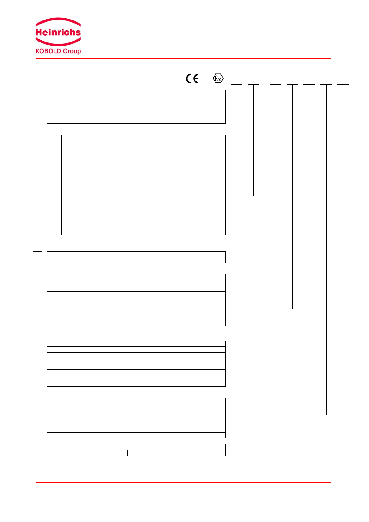
4. General information about explosion protection
Acc. Directive 2014/34/EU (ATEX)
Example designation
0158
II
2G
Ex
ia
IIC
T6
Gb
Equipment groups
I
Equipment group I applies to equipment intended for use in underground
parts of mines as well as those parts of surface installations of such mines
endangered by firedamp and/or combustible dust.
II
Equipment group II applies to equipment intended for use in other places
liable to be endangered by explosive atmospheres. This group is subdivided
into three categories.
Equipment category
Designation for
gases
Designation for
dust
Definition
1G
(0)
1 D
(20)
Equipment in this category is intended for use in areas in which ex-
plosive atmospheres caused by mixtures of air and gases, vapours or
mists or by air/dust mixtures are present continuously, for long peri-
ods or frequently.
2 G
(1)
2 D
(21)
Equipment in this category is intended for use in areas in which ex-
plosive atmospheres caused by gases, vapours, mists or air/dust
mixtures are likely to occur.
3G
(2)
3D
(22)
Equipment in this category is intended for use in areas in which ex-
plosive atmospheres caused by gases, vapours, mists, or air/dust
mixtures are unlikely to occur or, if they do occur, are likely to do so
only infrequently and for a short period only.
(The numbers in round brackets correspond to the IEC Zones.)
Acc. EN 60079-0 ff / IEC 60079-0 ff
Ex = Explosion-proof electrical equipment
Types of protection
General requirements
IEC 60079-0
„d“
Flameproof enclosure
IEC 60079-1
„q”
Sand filling
IEC 60079-5
„e“
Increased safety
IEC 60079-7
„i“
Intrinsic safety (ia, ib)
IEC 60079-11
„n“
Non-incentive electrical equipment
IEC 60079-15
„m“
Encapsulation
IEC 60079-18
„t"
Equipment dust ignition protection by enclo-
sure "t" (ta, tb or tc)
EN 60079-31
Explosion groups
Gases and vapours
IIA
Acetone, benzene, fuel oil, ethanoic acid
IIB
City gas, ethylene, isoprene
IIC
Acetylene, hydrogen, carbon bisulphide
Dust Atmospheres
IIIA
Fibers and flyings
IIIB
Non-conductive dusts
IIIC
Metal dusts
Temperature classes
Maximum surface temperature
Temperature class
450 °C
842 °F
T1
300 °C
572 °F
T2
200 °C
392 °F
T3
135 °C
275 °F
T4
100 °C
212 °F
T5
85 °C
185 °F
T6
Equipment protection level, EPL
Gases: Ga, Gb oder Gc
Dust: Da, Db or Dc
Explosion protection designations [square brackets] refer to “Related electrical equipment or circuits.”
Ex-Supplementary manual ES
Page 7 of 8
5. Scope of application
The ES transducer is used in flow meters of the BGN, BGF and TSK type series in the BA fill level indica-
tor and the DWF density meter. This covers the areas of volume flow rate measurement, fill level meas-
urement according to the principle of positive displacement and density measurement. The ES* transduc-
er is intended for installation in a housing providing a minimum IP class of protection from IP20.
6. Mode of operation and system layout
The electric ES-type transmitter serves to transform the needle position of the mechanical measuring
system into a proportional 4-20mA signal or to the field bus interface connection.
6.1 Measuring principle
The position of the float and/or lifting body is transferred to the needle axis through a magnetic system.
The ES transducer uses 2 magnetic field sensors to measure the field of a magnet attached to the needle
axis in order to generate an output current of 4...20 mA. The usual non-linear scale is in this case linear-
ised with a maximum of 16 data points.
The terrestrial magnetic field and moderately sized homogenous external magnetic fields are largely com-
pensated by the applied differential measurement of the 2 magnetic field sensors.
7. Electrical connection
7.1 ES type
The electrical connection of the ES type is provided through an intrinsically safe 2-wire supply and signal
circuit of 4-20 mA.
7.2 ES-PPA and ES-FF type
The ES-PPA and/or ES-FF types are “FISCO field devices”and the electrical connection is realised via an
intrinsically safe 2-wire field bus circuit according to the FISCO model.
As an option, devices may also be connected to intrinsically safe field bus circuits that do not correspond
to the FISCO model. In this case careful attention must be paid to the maximum electrical values (Ui, Ii,
Pi, Li and Ci) as described below.
8. Ex-Marking in accordance to ATEX directive 2014/34/EU and IECEx
II 2G Ex ia IIC T6 Gb Ex ia IIC T6 Gb
DMT 00 ATEX E 075 BVS 16.####
9. Electrical and thermal characteristics
9.1 For the version ES
9.1.1 Supply and signal circuit (terminals 1 and 2)
Voltage Ui DC 30 V
Current Ii 150 mA
Power Pi 1 W
Effective internal inductance Li 0,24 mH
Effective internal capacitance Ci 16 nF
9.1.2 Binary outputs 1 and 2: potential-free optocoupler output circuit (terminals 3-4 and 5-6)
each
Voltage UiDC 30 V
Current Ii20 mA
Power Pi100 mW
Effective internal inductance Li4 µH
Effective internal capacitance Ci16 nF
Ambient temperature range Ta -40 °C to + 70 °C

Page 8 of 8
Ex-Supplementary manual ES
9.2 For the versions ES-PPA (terminals 7 and 8) or ES-FF (terminals 9 and 10)
For the use as a field device in an intrinsically safe field bus system in acc. FISCO (IEC 60079-11, An-
nex G), or for the connection to intrinsically safe electric circuits.
Parameters for the transmitter:
Ui= 32 V
Ii= 280 mA
Pi= 2W
Ci < 5nF
Li < 10µH
The ambient temperature range amounts to -40 °C to +70 °C.
10. Special conditions for safe application
10.1 Environmental impacts on the transmitter.
Environmental impacts, like the process temperature of the flow meter and the installed ES* transmitter
must be considered. See also item 7 of the measuring device’s general instruction manual.
10.2 Atmospheric conditions
In accordance with EN 1127, a “potentially explosive atmosphere“ is defined as a mixture of air and com-
bustible gases, vapour, mist or dust under atmospheric conditions. Such conditions are defined in EN
13463-1, para. 1, with values Tatm = -20 °C to +60 °C and Patm = 0.8 to 1.1 bar. Outside this range, safe-
ty parameters for most ignition sources are not available. Usually, variable-area flow meters operate under
operating conditions outside the atmospheric conditions of 0.8 to 1.1 bar. Irrespective of the zone classifi-
cation –safety parameters of explosion protection –are basically not applicable to the inside of the meas-
uring tube. Therefore operation with combustible products is only allowed if a potentially explosive air mix-
ture is not formed inside the flow meter. Where this condition is not met, the operator will need to assess
the ignition hazard in each individual case and give due consideration to existing parameters (e.g. pres-
sure, temperature, process product, materials of construction for the measuring tube).
10.3 Ground connection
In variable-area flow meters, it is possible under operating conditions for charge separation to occur in the
measuring tube due to the transport of non-conductive fluids and/or when the flow comes into contact with
non-conductive internals (e.g. liners, floats). For that reason, variable-area flow meters must be perma-
nently grounded by the operator by way of the process connections (flanges) in order to discharge electro-
static build-up. The operator is also responsible for extending the ground continuity of the process pipe-
line. If grounding cannot be made via the process connections (plastic process connections or undefined
connections), the flow meter must be connected to the local ground potential via the flanges. This connec-
tion only ensures electrostatic grounding of the device and does not meet the requirements for equipoten-
tial bonding.
11. Marking
Only devices bearing the Ex label may be operated in explosive environments.
Example type plates for the ES standard and ES-FF versions are presented below.
This manual suits for next models
2
Table of contents
Other Heinrichs Transmitter manuals


