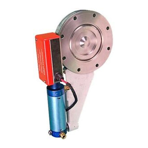
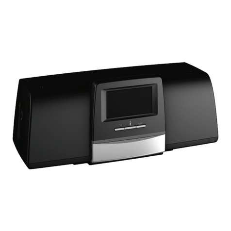
Heinzmann ARIADNE User manual

Copyright 2011 by Heinzmann GmbH & Co. KG. All rights reserved.
This publication may not be reproduced by any means whatsoever or passed on to any third parties.
5835 Manual DG 06 001-e / 09-10
Heinzmann GmbH & Co. KG
Engine & Turbine Management
Am Haselbach 1
D-79677 Schönau
Germany
Phone +49 7673 8208 - 0
Fax +49 7673 8208 - 188
www.heinzmann.com
V.A.T. No.: DE145551926
HEINZMANN
Engine & Turbine Management
ARIADNE
Knock Control
KC-01


The appropriate manuals must be thoroughly studied before instal-
lation, initial start-up and maintenance.
All instructions pertaining to the system and safety must be followed in
full. Non-observance of the instructions may lead to injury to persons
and/or material damage.
HEINZMANN shall not be held liable for any damage caused through
non-observance of instructions.
Independent tests and inspections are of particular importance for all
applications in which a malfunction could result in injury to persons or
material damage.
All examples and data, as well as all other information in this manual
are there solely for the purpose of instruction and they may not be used
for special application without the operator running independent tests
and inspections beforehand.
HEINZMANN does not guarantee, neither expressly nor tacitly, that
the examples, data or other information in this manual is free from er-
ror, complies with industrial standards or fulfils the requirements of any
special application.
To avoid any injury to persons and damage to systems, the following
monitoring and protective systems must be provided:
Overspeed protection independent of the rpm controller
HEINZMANN shall not be held liable for any damage caused through
missing or insufficiently rated overspeed protection.
thermal overload protection
The following must also be provided for alternator systems:
Overcurrent protection
Protection against faulty synchronisation for excessively-large fre-
quency, voltage or phase difference
Directional contactor
The reasons for overspeeding may be:
Failure of positioning device, control unit or its auxiliary devices
Linkage sluggishness and jamming
The following must be observed before an installation:
Always disconnect the electrical mains supply before any interven-
tions to the system.
Only use cable screening and mains supply connections that corre-
spond with the European Union EMC Directive
Check the function of all installed protection and monitoring systems

Please observe the following for electronically controlled injection
(MVC):
For common rail systems each injector line must be equipped with a
separate mechanical flow-rate limiter
For unit pump (PLD) and pump-injector unit (PDE) systems, the
fuel enable is first made possible by the solenoid valve’s control
plunger motion. This means that in the event of the control plunger
sticking, the fuel supply to the injection valve is stopped.
As soon as the positioning device receives power, it can actuate the
controller output shaft automatically at any given time. The range of the
controller shaft or control linkage must therefore be secured against un-
authorised access.
HEINZMANN expressly rejects any implied guarantee pertaining to
any marketability or suitability for a special purpose, including in the
event that HEINZMANN was notified of such a special purpose or the
manual contains a reference to such a special purpose.
HEINZMANN shall not be held liable for any indirect and direct dam-
age nor for any incidental and consequential damage that results from
application of any of the examples, data or miscellaneous information
as given in this manual.
HEINZMANN shall not provide any guarantee for the design and planning
of the overall technical system. This is a matter of the operator its planners
and its specialist engineers. They are also responsible for checking whether
the performances of our devices match the intended purpose. The operator is
also responsible for a correct initial start-up of the overall system.

Contents
Table of contents
1 Safety Instructions and Related Symbols .............................................................................. 1
1.1 Basic Safety Measures for Normal Operation................................................................. 2
1.2 Basic Safety Measures for Servicing and Maintenance .................................................. 2
1.3 Before Putting an Installation into Service after Maintenance and Repair Works......... 3
2 Introduction ............................................................................................................................ 5
3 Knocking Combustion............................................................................................................ 7
4 ARIADNE Advantages........................................................................................................... 9
5 ARIADNE Design and Features ......................................................................................... 11
6 Application............................................................................................................................ 13
6.1 Stand-alone Knock Control Unit ................................................................................... 14
6.2 Fully integrated Knock Control Unit ............................................................................ 15
7 Knock Sensor........................................................................................................................ 17
7.1 Technical Data Knock Sensor ....................................................................................... 17
7.2 Installation..................................................................................................................... 18
8 Inputs and Outputs............................................................................................................... 21
8.1 Power Supply................................................................................................................. 21
8.2 Inputs ............................................................................................................................. 21
8.3 Outputs .......................................................................................................................... 22
8.4 Communication.............................................................................................................. 22
9 Technical Data ..................................................................................................................... 23
10 Wiring Diagram.................................................................................................................. 25
11 Dimensions ......................................................................................................................... 27
12 Index of Figures ................................................................................................................. 29
13 Download of Manuals ........................................................................................................ 31


1 Safety Instructions and Related Symbols
ARIADNE Knock Control 1
1Safety Instructions and Related Symbols
This publication offers wherever necessary practical safety instructions to indicate inevitable
residual risks when operating the engine. These residual risks imply dangers to
- Personnel
- Product and machine
- The environment
The primary aim of the safety instructions is to prevent personal injury!
The signal words used in this publication are specifically designed to direct your attention to possi-
ble damage extent!
DANGER indicates a hazardous situation the consequence of which could
be fatal or severe injuries if it is not prevented.
WARNING indicates a hazardous situation which could lead to fatal inju-
ry or severe injuries if it is not prevented.
CAUTION indicates a hazardous situation which could lead to minor in-
juries if it is not prevented.
NOTICE indicates possible material damage.
Safety instructions are not only denoted by a signal word but also by haz-
ard warning triangles. Hazard warning triangles can contain different
symbols to illustrate the danger. However, the symbol used is no substitute
for the actual text of the safety instructions. The text must therefore al-
ways be read in full!
This symbol does not refer to any safety instructions but offers important
notes for better understanding the functions that are being discussed.
They should by all means be observed and practiced.

1 Safety Instructions and Related Symbols
2ARIADNE Knock Control
1.1 Basic Safety Measures for Normal Operation
The installation may be operated only by authorized persons who have been duly
trained and who are fully acquainted with the operating instructions so that they are
capable of working in accordance with them.
Before turning the installation on please verify and make sure that
- only authorized persons are present within the working range of the engine;
- nobody will be in danger of suffering injuries by starting the engine.
Before starting the engine always check the installation for visible damages and make
sure it is not put into operation unless it is in perfect condition. On detecting any faults
please inform your superior immediately!
Before starting the engine remove any unnecessary material and/or objects from the
working range of the installation/engine.
Before starting the engine check and make sure that all safety devices are working
properly!
1.2 Basic Safety Measures for Servicing and Maintenance
Before performing any maintenance or repair work make sure the working area of the
engine has been closed to unauthorized persons. Put on a sign warning that mainte-
nance or repair work is being done.
Before performing any maintenance or repair work switch off the master switch of the
power supply and secure it by a padlock! The key must be kept by the person perform-
ing the maintenance and repair works.
Before performing any maintenance and repair work make sure that all parts of engine
to be touched have cooled down to ambient temperature and are dead!
Refasten loose connections!
Replace at once any damaged lines and/or cables!
Keep the cabinet always closed. Access should be permitted only to authorized per-
sons having a key or tools.
Never use a water hose to clean cabinets or other casings of electric equipment!

1 Safety Instructions and Related Symbols
ARIADNE Knock Control 3
1.3 Before Putting an Installation into Service after Maintenance and Repair
Works
Check on all slackened screw connections to have been tightened again!
Make sure the control linkage has been reattached and all cables have been reconnected.
Make sure all safety devices of the installation are in perfect order and are working
properly!

1 Safety Instructions and Related Symbols
4ARIADNE Knock Control

2 Introduction
ARIADNE Knock Control 5
2Introduction
Knocking is an uncontrolled combustion process of gas engines, generating high frequency
pressure vibrations in the combustion chamber, reducing engine performances and potentially
leading to destructive engine damages in addition to undesirable noise emissions.
By limiting the compression ratio and restricting, for instance, the use of low methane number
fuel gas, knocking combustion is, beside misfiring, one of the major limitation for increased
performances and engine development.
Knocking combustion is a stochastic process. With the same operation conditions, the knock-
intensity is changing from cycle to cycle and from cylinder to cylinder, making a cylinder
individual analysis necessary for best performances.
These 3 head-lines point out the key role taken by the knock control in today’s spark-ignited
engine management. It must accurately detect knock of each cylinder individually and main-
tain an optimal operation under all conditions while protecting the engine from every damage.
Performance and Protection, these words have been the heart of the design for ARIADNE,
HEINZMANN’s Knock Control System (↑Figure 1). With ARIADNE on board, HEINZ-
MANN will give you the thread to guide you in your quest for improved engine performances
and avoid the threat of knock.
Figure 1: ARIADNE, HEINZMANN’s Knock Control Unit


3 Knocking Combustion
ARIADNE Knock Control 7
3Knocking Combustion
Researches on knocking combustion in spark-ignited engines started in the early 1920th years,
at the beginning of engine optimization and was already discovered quite short after the in-
vention of the SI engine itself. After some time it became evident that knocking is caused by
auto ignition of the air-fuel mixture in front of the flame propagating across the combustion
chamber when the temperature and pressure conditions of the end gas have reached a critical
level. In addition to annoying noise emissions, which gave the name “Knocking”, the engine
performances are reduced and the engine itself can be destroyed by this uncontrolled combus-
tion process. The main factors acting on the knock level are: compression ratio, cylinder fill-
ing, spark advance, intake pressure and temperature, air-fuel ratio and fuel gas properties.
During a normal combustion (↑Figure 2 Normal combustion, cylinder pressure without
knocking) a turbulent flame is propagating, changing the air-fuel mixture into burned gas.
This reaction releases energy which leads to a certain pressure increase in the combustion
chamber. The pressure is considered homogeneous in the cylinder since the propagation speed
of the flame front is rather small (10-50 m/s) and the combustion does not create pressure
waves of high amplitudes. The propagation of the flame front needs a certain time during
which the end gas is submitted to increasing pressure and temperature conditions which can
reach the auto ignition critical level. The auto ignition of a part of the air-fuel mixture has for
result its combustion at almost constant volume or at least at very high combustion speed (the
mixture is instantaneously transformed into burned gas) . This kind of detonation leads to a
high and quick local pressure increase, followed by vibrations of the whole cylinder filling
and progressive equalization of the pressures in the cylinder. The pressure oscillations have a
fundamental frequency range of 2000-8000 Hz, mostly depending on the gas temperature in
the combustion chamber and the cylinder diameter (↑Figure 3 Uncontrolled combustion, cyl-
inder pressure with heavy knocking). The abrupt characteristic of the phenomenon can be
explained by the high propagation speed of the pressure waves (500-1000 m/s), compared to
the normal propagation speed of the flame front (10-50 m/s). Knocking combustion leads to
higher heat transfers between burned gas and cylinder walls and consequently reduces engine
efficiency. The higher mechanical and thermal stress on the cylinder walls (vibrations and
heat transfers) can be destructive specially on already high loaded engines (erosion or destruc-
tion by fatigue of piston, cylinder head, liner, piston compression rings, pre-chamber …).
After 80 years of research, it is clear that the question today is not how to basically suppress
knocking combustion as such, which is illusory, but how to best deal with this remaining
threat in the future engine developments, making a reliable knock control system a major key
for increased engine performances.

3 Knocking Combustion
8ARIADNE Knock Control
Cylinder pressure without knocking
0
50
100
150
200
250
-90-75-60-45-30-150 153045607590
Crankshaft angle [°]
Cylinder pressure [bar]
Figure 2: Normal combustion, cylinder pressure without knocking
Cylinder pressure with heavy knocking
0
50
100
150
200
250
-90-75-60-45-30-15 0 153045607590
Crankshaft angle [°]
Cylinder pressure [bar]
Figure 3: Uncontrolled combustion, cylinder pressure with heavy knocking

4 ARIADNE Advantages
ARIADNE Knock Control 9
4ARIADNE Advantages
As part of a gas engine management system, ARIADNE brings advantages in term of protec-
tion, performances and costs, mainly:
ARIADNE protects gas engines against damages caused by knocking combustion.
With ARIADNE on board, engines can safely be run close to the knock limit which means
high efficiency and low emissions.
ARIADNE makes the use of fluctuating fuel gas quality possible.
Less electronics on-engine: a single ARIADNE unit can monitor up to 20 knock sensors
i.e. a whole engine in most cases.
ARIADNE monitors each cylinder, cycle by cycle, individually, making a fine single cyl-
inder tuning possible, thus improving both performances and emissions.
Low cost application possible: ARIADNE can monitor several cylinders using a single
sensor.
ARIADNE is full compatible to other HEINZMANN systems and HEINZMANN ad-
vanced user interface DcDesk 2000.
ARIADNE is available in 2 designs (IP00 and IP55) and can be mounted off- or on-
engine.
With its integrated diagnostic display, ARIADNE facilitates quick servicing.
From stand-alone unit to highly integrated part of engine management, the large range of
I/O provided makes ARIADNE suitable for all applications.


5 ARIADNE Design and Features
ARIADNE Knock Control 11
5ARIADNE Design and Features
ARIADNE monitors up to 20 separate vibration sensors (industry standard wide-band
piezoelectric vibration sensors, Bosch-type or compatible ones) placed on the engine
block or cylinder heads. In most cases one unit can protect a whole engine equipped with
one knock sensor per cylinder. For engines with more than 20 cylinders, 2 units can easily
be connected over CAN-bus.
Figure 4: Typical Knock Sensor, Bosch-Type
ARIADNE makes use of dedicated Digital Signal Processors to suppress all kind of knock
sensor signal corruptions, for instance due to vibrations caused in normal operation by the
different gas engine components. Configurable knock measuring windows, digital ampli-
fiers, band-pass filters and integrators are provided ensuring that the knock level calculat-
ed by ARIADNE fairly reflects the real knock intensity inside the cylinder. Of course all
parameters (limit values, gains …) are configurable and can be made, for instance, speed-
or load-dependant.
Figure 5: ARIADNE functional Overview

5 ARIADNE Design and Features
12 ARIADNE Knock Control
Cylinder individual parametrizing and analysis for finest reaction to knock events and best
compensation to the stochastic aspect of knocking combustion. This allows to adapt the
operation parameters (mainly spark timing, eventually also load and air-fuel ratio) for
each cylinder individually ensuring best cylinder individual performances and improving
engine emissions.
ARIADNE can either monitor all cylinders using separate individual sensors or monitor
several cylinders using the same sensor (low cost).
Optionally ARIADNE can be delivered in 2 designs: IP00 version with/without top hat
rail to be placed inside a cabinet near the engine (sensor connection over terminal strips)
or IP55 version for direct on-engine mounting (sensor connection over plug-in connect-
ors).
ARIADNE has been developed to fit in all possible gas engine control designs, from a
stand-alone unit to a fully integrated part of the gas engine management system, thus fea-
tured with a large range of I/O possibilities. With 1 analog input (0-5V / 4-20mA), 1 ana-
log output (0-5V / 4-20mA), 4 digital outputs, 2 CAN (Hzm-CAN, CANopen, Devicenet,
J1939 or other proprietary protocols) and 1 RS-485 (MOD-bus) serial interfaces, ARI-
ADNE will suit all applications.
For quick diagnostic, ARIADNE is equipped of a 2-digits display (7-segment LEDs), giv-
ing to customers or service engineers first indication on knock occurrences (light or heavy
knocking combustion detected, cylinder(s) concerned) or on other errors detected by the
unit, without connecting a PC.
Figure 6: ARIADNE quick diagnostic display
ARIADNE is full compatible with other HEINZMANN products like speed and load con-
trollers, air-fuel ratio control units, ignition modules, generator management systems and
can communicate with these over CAN-bus (Hzm-CAN). For flexible and extended con-
figuration and visualization of input and output data, ARIADNE integrates a serial inter-
face to DcDesk 2000, HEINZMANN’s Windows®user interface programme, widely used
on all other HEINZMANN digital products.

6 Application
ARIADNE Knock Control 13
6Application
ARIADNE monitors up to 20 vibration sensors placed on the engine structure. Depending on
the configuration, one sensor is assigned to one or several cylinders. In comparison to normal
cycles, knocking combustion produces high frequency pressure oscillations which act as a
vibration source on the engine structure and make the knock sensor signal clearly higher for
certain frequencies. By using a configurable bandpass filter ARIADNE only monitors this
engine specific knock frequency suppressing all non knock-related usual engine vibrations.
ARIADNE also needs engine speed and phase to determine, for each cylinder individually,
the time window where knock combustion is susceptible to occur (usually, knock is measured
just after cylinder top dead centre , for example between TDC and TDC+50°crank) (↑Figure
5 ARIADNE functional Overview).
Several measures can be taken to reduce knock:
In case of light knocking, the first action is normally to reduce step by step the spark angle
(for example in steps of 0,5° crank). If knock combustion disappears the spark angle is
progressively increased back to its nominal value.
If knock combustion is still present after the spark angle has been reduced to its minimum,
the engine has to be gradually derated to avoid potential damages: the load is reduced step
by step and increased back to its nominal value if knock disappears.
If the 2 previously described actions have not allowed to reduce the knock level signifi-
cantly, a correction of the air-fuel ratio might be necessary.
If the knock level detected increases up to the heavy knocking limit, indicating a very high
knock severity with potential fatal damages, the engine must be stopped.
ARIADNE is particularly adapted to following engine types:
V- or inline gas engines
Rated speed of 300 … 1800 rpm
Rated load from 100 … 8000 kW
Number of cylinders from 4 … 20
ARIADNE has been designed to suit all gas engine control system applications. In order to
give an idea of the range of possible applications, 2 usual configurations are described in the
following in some more details.

6 Application
14 ARIADNE Knock Control
6.1 Stand-alone Knock Control Unit
When used as stand-alone unit, ARIADNE’s analog output can directly be wired to the ig-
nition system, transmitting the knock severity measured on the engine (maximum of all
cylinders knock levels). This 4-20mA or 0-5V signal acts as offset on the engine nominal
spark angle. In case of heavy knocking, the engine stop signal is transmitted over digital
output to the speed/load controller. For more precise knock control, a load signal can be
connected to ARIADNE (for example an electrical load measurement or a boost pressure
sensor). Optionally ARIADNE can provide a load reduction algorithm over digital output
or CAN-bus.
Figure 7: Stand-alone Knock Control Unit
This manual suits for next models
1
Table of contents
Other Heinzmann Control Unit manuals
Popular Control Unit manuals by other brands
Nice
Nice Moon MC824H FUNCTIONS
Honeywell
Honeywell VP525C installation instructions
Bailey
Bailey Infi 90 NTPL01 Instruction

Maple Systems
Maple Systems iR-A Series instruction manual
Texas Instruments
Texas Instruments TA 5 1 Q15B5EVM-K Series user guide
Honeywell
Honeywell Notifier XP6-R Installation and maintenance instructions
