2
Basic Installation Instructions
Most field problems occur because dirt and debris present in
the system at the time of installation becomes trapped in the
check valves. The system should be flushed before the valve
is installed. If the system is not flushed until after the valve is
installed, remove both check modules from the valve and open
the inlet shutoff to allow water to flow for a sufficient time to flush
debris from the water line. If debris in the water system contin-
ues to cause fouling, a strainer can be installed upstream of the
backflow assembly.
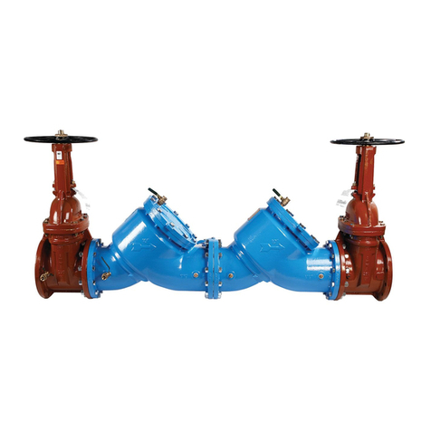
Series C200 and C300 may be installed in either horizontal or
vertical position as long as the backflow assembly is installed in
accordance with the direction of the flow arrow on the assem-
bly and the local water authority approves the installation. The
assembly should be installed with adequate clearance around the
valve to allow for inspection, testing, and servicing. A minimum
clearance of 12" is needed between the lower portion of the
assembly and the floor or grade.
The control valves on the OSY-TS model have integrated super-
visory tamper switches that require connection to a fire alarm
control panel.
NOTICE
Assembly body should not be painted.
Horizontal Installation
Vertical Installation
Wiring the Tamper Switch
The supervisory tamper switch consists of two SPDT switches.
The device is designed to send a signal when the valve is closed
and when the switch is removed from the valve. In the neutral
position, the switch indicates the valve is fully open. Closing
the valve causes the switch rod to come out of the valve stem
groove, activating the switch. Removing the device also activates
the switch.
Use the schematic diagram and the wiring notes for proper
wiring of the tamper switch to a fire alarm control panel. (For
more information refer to Tamper Switch Wiring Instructions at
watts.com.)
CAUTION
!
Before wiring supervisory switches in fire protection sys-
tems, refer to the following standards:
NFPA 13: Standard for the Installation of Sprinkler Systems
NFPA 25: Inspection, Testing, Maintenance of Water-based Fire
Protection Systems
NFPA 70: National Electrical Code
NFPA 72: National Fire Alarm Code
CSA C22.1 NO.1 Canadian Electrical Code, Part 1, Safety
Standard for Electrical Installations Section 32
CAN/ULC-S524, Standard for Installation of Fire Alarm Systems
Wiring Notes
• Connection to power limited circuitry is required.
• The auxiliary switch is for supplemental use only and shall not
be used for fire alarm signaling applications.
• Switch functions are checked at the factory. Checking the
switch after field installation is strongly advised. Check conti-
nuity with the valve fully open. Switch functions activate within
two (2) turns from open.
WARNING
!
Metallic conduit required by NEC for proper grounding conduit
joint must be sealed with a conductive sealant.
Install switch in accordance with National Electrical Code and/or
local ordinances.
Wiring methods shall be in accordance with CSA C22.1,
Canadian Electrical Code, Part 1, Safety Standard for Electrical
Installations, Section 32 and CAN/ULC-S524, Standard for
Installation of Fire Alarm Systems Assure All Devices Are Properly
Grounded.
