manuals.online logo
Brands
  1. Home
  2. •
  3. Brands
  4. •
  5. Texas Instruments
  6. •
  7. Control Unit
  8. •
  9. Texas Instruments TA 5 1 Q15B5EVM-K Series User manual

Texas Instruments TA 5 1 Q15B5EVM-K Series User manual

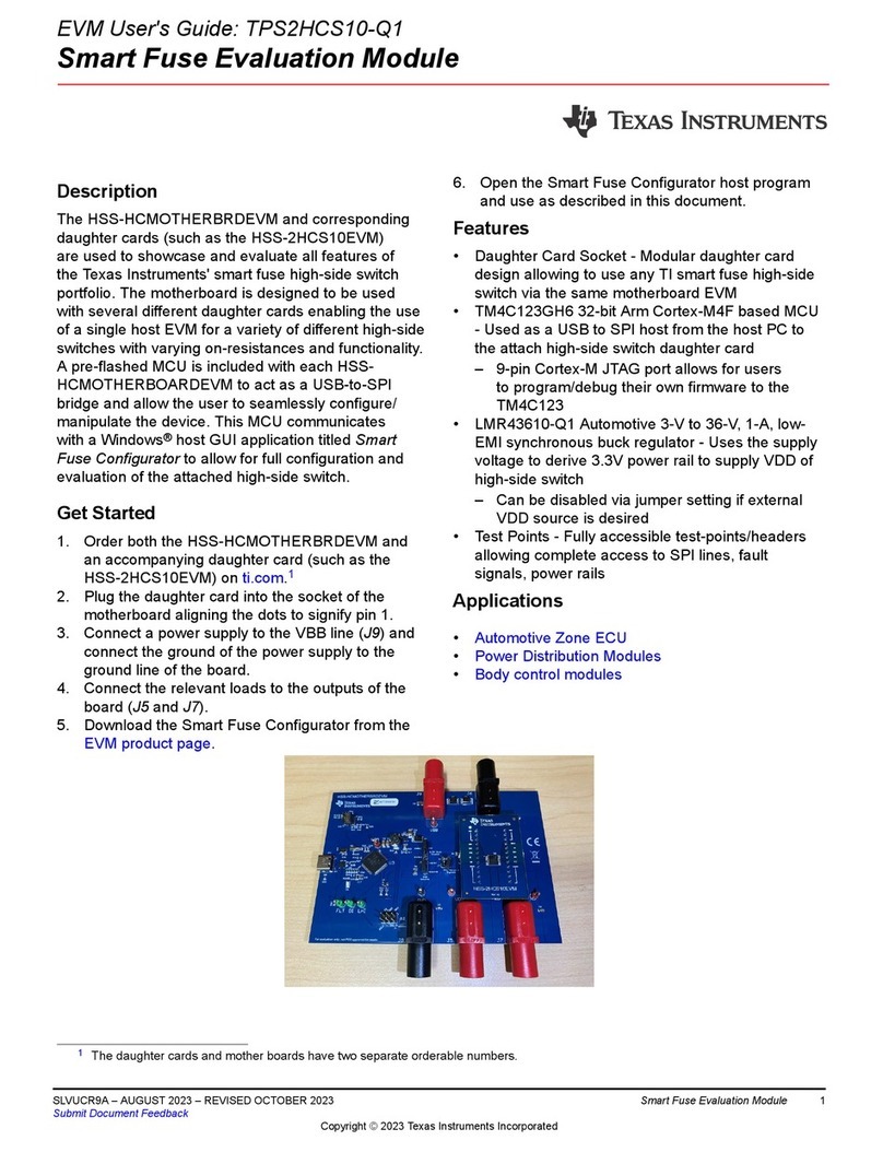
EVM User's Guide: TAC5412Q15B5EVM-K TAC5411Q15B5EVM-K
TAA5412Q15B5EVM-K
TAx5x1xQ15B5EVM-K Evaluation Module
Description
This user guide describes the functionality of
the TAC5412Q15B5EVM-K, TAC5411Q15B5EVM,
or TAA5412Q15B5EVM-K evaluation kit. The
TAx5x1xQ15B5EVM-K evaluation module (EVM)
allows the user to test the capabilities of
Texas Instruments’ two-channel high-performance
ADC TAA5412-Q1, a two-channel TAC5412-Q1 or
TAC5411-Q1, a single-channel high-performance
codec. Other variants listed in Table 1-1 are also
supported where users will replace the U1 unit with
the device of interest. The evaluation module is paired
with the AC-MB, a flexible motherboard that provides
power, control, and digital audio data to the evaluation
module.
Get Started
1. Order the EVM from the TAx5x12 product folder.
2. Download the latest TAx5x12 data sheet.
3. Request access and download the PPC3 GUI
from the TAx5x12 product folder.
Features
• Complete evaluation kit for the TAC5x12-Q1
(two-channel codec), TAC5x11-Q1 (single-channel
codec), or TAA5412-Q1 (two-channel ADC).
• High-performance mono/stereo codec dynamic
range: 120 dB DAC and 110 dB ADC or standard
performance 106 dB DAC and 102 dB ADC
• On-board microphones provided for voice
recording testing
• Direct access to digital audio signals and control
interface for simple end-system integration
• USB connection to PC provides power, control,
and streaming audio data for easy evaluation
• On-board diagnostic scenarios for analog audio
input
Applications
•Emergency E-Call
•Telematics control unit
•Automotive active noise cancellation
•Automotive head units
www.ti.com Description
SLAAEC6 – OCTOBER 2023
Submit Document Feedback
TAx5x1xQ15B5EVM-K Evaluation Module 1
Copyright © 2023 Texas Instruments Incorporated
1 Evaluation Module Overview
1.1 Introduction
The TAx5x1XQ15B5EVM is an evaluation module (EVM) designed to demonstrate the performance and
functionality of the TAx5x1x-Q1 family of devices. This family includes the devices shown in Table 1-1 with
differences in performance and function noted.
Table 1-1. TAx5x1x-Q1 Family
Device ADC DR (dB) DAC DR (dB) Feature
TAC5412-Q1 110 120 Stereo codec
TAC5411-Q1 110 120 Mono codec
TAC5312-Q1 102 106 Stereo codec
TAC5311-Q1 102 106 Mono codec
TAA5412-Q1 110 NA Stereo ADC
Evaluation Module Overview www.ti.com
2TAx5x1xQ15B5EVM-K Evaluation Module SLAAEC6 – OCTOBER 2023
Submit Document Feedback
Copyright © 2023 Texas Instruments Incorporated
1.2 Kit Contents
• TAC5412-Q1, TAC5411-Q1 or TAA5412-Q1 device
• TAx5x1XQ15B5 EVM/daughterboard
• AC-MB controller/motherboard
1.3 Specification
The TAx5x1XQ15B5EVM-K evaluation module (EVM) paired with the AC-MB, a flexible motherboard that
provides power, control, and digital audio data to the evaluation module, allows the user to record and playback
audio signals. The configuration for the TAx5x1x-Q1 family of devices is done through the PurePath™ Console 3
(PPC3) GUI.
1.4 Device Information
• TAC5412-Q1, a low-power, high-performance, stereo audio codec with integrated programmable boost, mic
bias, and diagnostics.
• TAC5411-Q1, a low-power, high-performance, mono audio codec with integrated programmable boost, mic
bias, and diagnostics.
• TAC5312-Q1, a low-power stereo audio codec with integrated programmable boost, mic bias, and
diagnostics.
• TAC5311-Q1, a low-power mono audio codec with integrated programmable boost, mic bias, and diagnostics.
• TAA5412-Q1, a low-power, high-performance, stereo audio ADC with integrated programmable boost, mic
bias, and diagnostics.
2 Hardware Overview
The evaluation kit consists of the TAx5x1XQ15B5EVM daughterboard and the AC-MB controller board. The
controller board provides the evaluation module power, control, and digital audio signals. The daughterboard
contains the TAx5x12-Q1 device and the input and output connections. Some components are not populated in
the EVM depending on the selected device.
USB Power
Selection
+5 V
USB Data
USB Vbus
S/PDIF Out
S/PDIF IN
VINL/R
SPI
I2C
XMOS ASI
9211 ASI
External
Power
+5-V Input
Level
Translator
Buffer
Mux AC-MB ASI EVM ASI
+3.3 V
+1.8 V
+1 V
Power-On Reset
JTAG
IOVDD
Selection
IOVDD
/POR
/RESET_SW
/RESET
AC_MB_EVM_Connector
IOVDD
+5 V
MCLK
BCLK
FSYNC
DIN 1-4
DOUT 1-4
SDA
SCL
MISO
MOSI
SCLK
/SS 1-2
/RESET
GPI 1-2
GPO 1-2
GPIO
XMOS
Interface
PCM9211
Interface
Optical Input
Optical Output
Analog Input
USB
XTAG
Power-On Reset
TAC5XXX
5x5
IC ASI
GPIO1
IC I2C
LDO
+3.3 V
BOOST VBATIN
VBAT
Selection
DIAGNOSTIC
INPUT
SELECTION
INX
+5 V
IOVDD
+1.2 V
AVDD
Selection
+1.8 V
BSTVDD
Selection
AVDD +3.3 V
AC_MB EVM
Power Rails
Main
Rest
External ASI
Connector
Digital Audio
Selection Switch
I2C and SPI
Test Points
AUDIO INPUT
CONNECTION
AUDIO OUTPUT
CONNECTION
HEADER
VBAT
IOVDD
AVDD
BSTVDD
OUTX
GPOXA
HEADER HEADER
I2S
Selection
EXT-AP
DIGMIC
HEADER
GPIO1
Figure 2-1. TAx5x1xQ1 EVM Block Diagram
www.ti.com Evaluation Module Overview
SLAAEC6 – OCTOBER 2023
Submit Document Feedback
TAx5x1xQ15B5EVM-K Evaluation Module 3
Copyright © 2023 Texas Instruments Incorporated
2.1 AC-MB Settings
2.1.1 Audio Serial Interface Settings
The AC-MB provides the digital audio signals to the evaluation module (EVM) from the universal serial bus
(USB), optical jack, stereo audio jack, and external audio serial interface (ASI) header. Figure 2-2 shows a block
diagram of the ASI routing on the AC-MB.
Figure 2-2. AC-MB Audio Interface Block Diagram
The SW2 switch on the AC-MB selects the audio serial bus that interfaces with the PCM6xx0EVM. Next to the
SW2 switch, the AC-MB has a quick reference table to identify the audio serial interface source options and
switch settings. The AC-MB acts as the controller for the audio serial interface. The AC-MB has three different
modes of operation: USB, optical or analog, or external ASI.
The serial interface clocks and data are provided from the USB interface. The USB audio class driver on the
operating system determines the sampling rate and format. The default settings for the USB audio interface
are 32-bit frame size, 48-kHz sampling rate, BCLK and FSYNC ratio of 256, and the format is time-division
multiplexing (TDM).
Hardware Overview www.ti.com
4TAx5x1xQ15B5EVM-K Evaluation Module SLAAEC6 – OCTOBER 2023
Submit Document Feedback
Copyright © 2023 Texas Instruments Incorporated
2.1.1.1 USB Mode
The OS detects the AC-MB as an audio device named TI USB Audio UAC2.0. Figure 2-3 shows the AC-MB
audio setting for the USB mode of operation.
Figure 2-3. AC-MB USB Audio Setting
2.1.1.2 Optical or Auxiliary Analog Audio Input Mode
Serial interface signals are provided from the PCM9211 digital transceiver, which is capable of sending digital
data to the EVM from an analog input or optical input. Meanwhile, the data from the EVM can be streamed
through the optical output.
Figure 2-4 shows the AC-MB audio setting for the optical and analog mode of operation.
Figure 2-4. AC-MB Optical or Auxiliary Analog Audio Input Setting
The optical output of the AC-MB streams the data captured on the EVM with the format determined by the input
source used. When there is an optical input connected, the LOCK LED must be ON. The PCM9211 streams
the audio serial interface clocks with the format determined by the optical input frame. The digital data from
the optical input is streamed to the EVM. If the optical input is not connected, the PCM9211 captures the input
signal provided through the analog input, and streams the signal to the EVM. This feature can be useful when
a digital input digital-to-analog converter (DAC) is connected to the AC-MB, providing an analog input for quick
evaluation. In auxiliary analog audio mode, the audio serial interface format is fixed to a 24-bit, 48-kHz, I2S
mode.
www.ti.com Hardware Overview
SLAAEC6 – OCTOBER 2023
Submit Document Feedback
TAx5x1xQ15B5EVM-K Evaluation Module 5
Copyright © 2023 Texas Instruments Incorporated
2.1.1.3 External Audio Interface Mode
In this mode, the audio serial interface clocks for the evaluation board are provided through connector J7 from
an external source. This architecture allows an external system to communicate with the evaluation board,
such as a different host processor or test equipment (Audio Precision™). The clocks generated from the USB
interface and PCM9211 are isolated with this setting. Figure 2-5 shows the AC-MB audio setting for the external
mode of operation.
Figure 2-5. AC-MB External Audio Interface Setting
Figure 2-6 shows how to connect the external audio interface. Odd-numbered pins are signal-carrying; even-
numbered pins are connected to ground.
Figure 2-6. AC-MB Connection with External Audio Serial Interface
Hardware Overview www.ti.com
6TAx5x1xQ15B5EVM-K Evaluation Module SLAAEC6 – OCTOBER 2023
Submit Document Feedback
Copyright © 2023 Texas Instruments Incorporated
2.1.2 AC-MB Power Supply
A single 5-V power supply powers the complete evaluation module system. However, the motherboard has
different low-dropout regulators (LDOs) integrated that provide the required power supply to the different blocks
of the board. Figure 2-7 shows a block diagram depicting the power structure of the AC-MB.
USB Power
Selection
+5 V
USB Vbus
External
Power
+5-V Input
+3.3 V
+1.8 V
+1 V
Power-On Reset
IOVDD
Selection
IOVDD IOVDD
+5 V
USB
+1.2 V
Power Rails
TO EVM
J9 J3
J4
J1
J5
Figure 2-7. Power-Supply Distribution of the AC-MB
The AC-MB can be powered from the host computer using the USB 5-V power supply (VBUS) by shorting
header J5, USB POWER. Additionally, the AC-MB can be powered from an external power supply connected to
terminal J4, EXTERNAL POWER. Header J5 must be open for external supply operation. The IOVDD voltage for
the digital signals provided to the EVM is generated on the motherboard from the main power supply (USB or
external).
The voltage levels available are 1.2 V, 1.8 V, and 3.3 V and can be selected via the J9 and J3 IOVDD header.
For 1.2-V operation, short pin 1 of header J9 and pin 2 of header J3; for 1.8-V operation, short pins 2 and 3 of
header J3; for 3.3-V operation, short pins 1 and 2 of header J3. The green POWER LED (D3) turns ON when the
motherboard is fully powered and the power supplies from the onboard LDOs are correct. The USB READY LED
indicates a successful USB communication between the AC-MB and the host computer.
www.ti.com Hardware Overview
SLAAEC6 – OCTOBER 2023
Submit Document Feedback
TAx5x1xQ15B5EVM-K Evaluation Module 7
Copyright © 2023 Texas Instruments Incorporated
2.2 TAx5x1xQ1EVM-K Hardware Settings
2.2.1 TAx5x1x-Q1 EVM Input Hardware Settings
The TAx5x1x-Q1 evaluation module has several input configuration options. The EVM allows the user to
evaluate the device across multiple operation modes. The different operation modes are highlighted in this
section.
Figure 2-8. TAx5x12-Q1 EVM Input Architecture for Channel 1 and 2
The IN1 and IN2 input architecture allows these two channels to be quickly configured to support any of the
supported operation modes. The INxP and INxM pins of the TAx5x1x-Q1 can optionally connect to onboard
microphones for quick evaluation of a microphone in AC or DC-coupled modes. Jumper configuration details can
be found in Table 2-1.
Hardware Overview www.ti.com
8TAx5x1xQ15B5EVM-K Evaluation Module SLAAEC6 – OCTOBER 2023
Submit Document Feedback
Copyright © 2023 Texas Instruments Incorporated
For TAC5x11-Q1 evaluation module, the DIN1P and DIN1M can be connected to IN1P and IN1M respectively
through jumper J63 and J64 as shown in Figure 2-9. Only IN1 Input Terminal is applicable in this evaluation
module from the configuration table below.
Figure 2-9. TAC5x11-Q1 EVM Input Architecture for Channel 1 and DIN1P/M
Table 2-1. Input Jumper Configuration
Input Terminal Input Mode Installed
Jumpers
Uninstalled
Jumpers
Input Swing Topology Register Setting
IN1 LINE-IN
Differential, AC-
coupled
J8, J20, J21 J4, J5, J6, J11,
J12, J15, J16
10 VRMS B0_P0_R80,
B0_P1_R115
LINE-IN Single-
ended, AC-
coupled
J6, J8, J12 (2-3),
J20, J21
J4, J5, J11, J15,
J16
5 VRMS B0_P0_R80,
B0_P1_R115
LINE-IN
Differential, DC-
coupled
J15, J16 J4, J5, J6, J11,
J12, J20, J21,
J8 (DUT MICBIAS
is not used)
10 VRMS B0_P0_R80
LINE-IN Single-
ended, DC-
coupled
J6, J12 (2-3), J15,
J16
J4, J5, J11, J20,
J21, J8 (DUT
MICBIAS is not
used)
5 VRMS B0_P0_R80
On-board Electret
Condenser
Microphone
(ECM) Differential,
AC-coupled
J4, J5, J8, J11,
J12 (1-2), J20, J21
J6, J15, J16 Refer to
Microphone data
sheet
B0_P0_R80,
B0_P1_R115
www.ti.com Hardware Overview
SLAAEC6 – OCTOBER 2023
Submit Document Feedback
TAx5x1xQ15B5EVM-K Evaluation Module 9
Copyright © 2023 Texas Instruments Incorporated
Table 2-1. Input Jumper Configuration (continued)
Input Terminal Input Mode Installed
Jumpers
Uninstalled
Jumpers
Input Swing Topology Register Setting
On-board Electret
Condenser
Microphone
(ECM) Single-
ended, AC-
coupled
J4, J5, J8, J11,
J12 (2-3), J20
J6, J15, J16, J21 Refer to
Microphone data
sheet
B0_P0_R80,
B0_P1_R115
On-board Electret
Condenser
Microphone
(ECM) Differential,
DC-coupled
J4, J5, J8, J11,
J12 (1-2), J15, J16
J6, J20, J21 Refer to
Microphone data
sheet
B0_P0_R80,
B0_P1_R115
On-board Electret
Condenser
Microphone
(ECM) Single-
ended, DC-
coupled
J4, J5, J8, J11,
J12 (2-3), J15, J16
J6, J20, J21 Refer to
Microphone data
sheet
B0_P0_R80,
B0_P1_R115
IN2 LINE-IN
Differential, AC-
coupled
J8, J22, J23 J7, J9, J13, J14,
J17, J18, J53
10 VRMS B0_P0_R85,
B0_P1_R115
LINE-IN Single-
ended, AC-
coupled
J7, J8, J14 (2-3),
J22, J23
J9, J13, J17, J18,
J53
5 VRMS B0_P0_R85,
B0_P1_R115
LINE-IN
Differential, DC-
coupled
J17, J18 J7, J9, J13, J14,
J22, J23, J53, J8
(DUT MICBIAS is
not used)
10 VRMS B0_P0_R85
LINE-IN Single-
ended, DC-
coupled
J7, J14 (2-3), J17,
J18
J9, J13, J22, J23,
J53, J8 (DUT
MICBIAS is not
used)
5 VRMS B0_P0_R85
On-board
Analog MEMS
microphone, AC-
coupled
J8, J9, J22, J23,
J53
J7, J13, J14, J17,
J18
Refer to the
Microphone data
sheet.
B0_P0_R85,
B0_P1_R115
On-board
Analog MEMS
microphone, DC-
coupled
J9, J17, J18, J53 J7, J13, J14, J22,
J23, J8 (DUT
MICBIAS is not
used)
Refer to the
Microphone data
sheet.
B0_P0_R85,
B0_P1_R115
Hardware Overview www.ti.com
10 TAx5x1xQ15B5EVM-K Evaluation Module SLAAEC6 – OCTOBER 2023
Submit Document Feedback
Copyright © 2023 Texas Instruments Incorporated
2.2.1.1 Line Inputs
For the line input configuration shown in Figure 2-8, the TAx5x1x-Q1 captures the audio signal provided through
RCA terminals J2 (IN1), J3 (IN2), header J54, or J55. The RCA white connector is connected to the INxP.
The RCA red connector is connected to the INxM. Depending on the differential or single-ended configuration,
populate the J6 or J7 jumper as described in Table 2-1 accordingly. The input accepted in this mode is a
differential 10-VRMS full-scale audio signal. If a single-ended source is used, the 5-VRMS signal is supported.
The gang potentiometer R50 and R51 provide the input bias resistors for this AC-coupled input mode depending
on the desired input swing and impedance.
Using the TAx5x1x-Q1 AC-Coupled external resistor calculator, enter the maximum input level and the desired
MICBIAS voltage to determine the resistance required to achieve full input swing as shown in Figure 2-10.
From the calculator example below, the maximum resistance allowed is 2399.4 Ohm, and the closest standard
resistance is 2375 Ohm. Based on this standard value resistance, the effective impedance looking into the
device is about 2184 Ohm. This effective input impedance forms a high pass filter with the external capacitor.
The Vcm is the common voltage for the respective MICBIAS and Input Swing. One can adjust the R50 and R51
potentiometer to get the common mode voltage (Vcm). By default, the EVM Vcm is set to 7.3 V.
Figure 2-10. AC-Coupled External Resistor Calculator
2.2.1.2 On-Board Microphone Input
For the on-board microphone input configuration shown in Figure 2-8, the TAx5x1x-Q1 records the audio
captured from MK1 (ECM) or U5 (Analog MEMS) microphones. For U5, the audio port is located at the bottom
of the board. Electret Microphone (MK1) is connected to IN1P/M, and MICBIAS is used to power the onboard
microphone, so header J8 must be installed. The MEMS microphone (U5) can be configured as a single-ended
or differential input and connected to IN2P/M. There must not be any connections to J2 or J3 while the onboard
microphone is used to preserve the performance of the microphone. Gain adjustment can be needed in the
device depending on the microphone sensitivity.
2.2.2 TAx5x1x-Q1 EVM Output Hardware Settings
The TAx5x1x-Q1 evaluation module has several output configuration options and offers flexibility to allow the
user to evaluate the device with different load conditions and configurations. The different configurations are
highlighted in this section.
www.ti.com Hardware Overview
SLAAEC6 – OCTOBER 2023
Submit Document Feedback
TAx5x1xQ15B5EVM-K Evaluation Module 11
Copyright © 2023 Texas Instruments Incorporated
2.2.2.1 TAx5x1x-Q1 Analog Audio Output
The EVM analog audio output port provides options for AC/DC-coupled and filter or filter-less paths for easy
evaluation. By default, the filter components are not populated.
Switch SW1 allows users to select respective loads for each output pair for 16 Ω, 604 Ω, or 10 kΩ if needed.
These resistors are for quick evaluation and can be bypassed for actual load. SW1 and the output RCA
connectors are located on the top left-hand side, shown in Figure 2-12.
Figure 2-11. TAC5x12-Q1 EVM Output Architecture for Channel 1 and 2
OUT1 and OUT2 audio output pins have connection options with external load or the on-board load selections.
A pair of RCA connectors, white from OUTP and red from OUTM, allow users to connect to external devices as
differential or single-ended. Jumper header J36 or J37 must be populated if single-ended is desired or removed
for differential configuration.
Table 2-2. SW1 Pin
SW1 pin Load Configuration Resistor Rating Output Module
Register Setting
1, 4, 7, 10 16 Ω 0.5 W B0_P0_R101
2, 5, 8, 11 604 Ω 0.125 W B0_P0_R101
3, 6, 9, 12 10 kΩ 0.4 W B0_P0_R101
Figure 2-12. TAC5x12-Q1 Analog Output Connections
For TAC5411-Q1 or TAC5311-Q1, OUT2 components are not populated.
Hardware Overview www.ti.com
12 TAx5x1xQ15B5EVM-K Evaluation Module SLAAEC6 – OCTOBER 2023
Submit Document Feedback
Copyright © 2023 Texas Instruments Incorporated
2.3 Diagnostics Hardware Setup
The diagnostics test circuitry, as shown in Figure 2-13, is not connected to any channel by default. For EVM rev.
E1 version, depending on the desired diagnostic test pins, connect J48 and J51 pin 1 to IN1P and IN1M or IN2P
and IN2M Test Point directly. In subsequent EVM versions, IN1P and IN1M are connected by default to the SW3
switch through J48 and J51 jumpers. Only one channel can be tested at a time with the on-board diagnostics
test circuitry. A fault is introduced by pressing SW2.
1
2 4
5
6
3
K1
G3VM-31HR(TR05)
21
SW2
+3.3V
INP-A
INM-A
INM-A
INP-A
MICBIASVBAT
DIAGSW
2
1
3
5
4
6
SW3
76STD01T
12
34
56
78
J52
330
R46
GND
GND
IN1P
IN1M
1
2
J48
1
2
J51
INM-A
INP-A
Place jumper on J48/51 for IN1x input. For
IN2x input remove J48/J51 jumper and
connect IN2x input on pin 1 of J48/51
Figure 2-13. TAx5x1x-Q1 EVM Diagnostic Circuitry
The diagnostic test selection is done by populating one jumper at any time on the J52 header either for input
to MICBIAS short, input to VBAT short, input to input short, or input to ground short. Once the connection is
established, press SW2 to initiate the test; the fault detection can then be verified through the device register.
The bidirectional arrow indicates moving the switch to the left for the IN1P test and to the right for the IN1M test.
TI's recommended settings for this diagnostics test circuit are discussed in this section. The following figures
below are based on a newer EVM revision, which has IN1P and IN1M connected by default through J48 and
J51.
2.3.1 Short to MICBIAS Setup
Figure 2-14 shows a short to the MICBIAS test. If using a single-ended input for the test channel, only connect
INxP.
Figure 2-14. Short to MICBIAS Diagnostic Test Setup
2.3.2 Short to VBAT Setup
A short to VBAT test requires an external voltage source connected to VBAT through J26 or onboard VBAT
through J27. If onboard VBAT is used, populate the J47 pin 1-2 jumper to enable the U4 switch regulator.
www.ti.com Hardware Overview
SLAAEC6 – OCTOBER 2023
Submit Document Feedback
TAx5x1xQ15B5EVM-K Evaluation Module 13
Copyright © 2023 Texas Instruments Incorporated
Figure 2-15. VBAT Connection
Figure 2-16. Short to VBAT Diagnostic Test Setup
2.3.3 Shorted Input Pins Setup
Shorted input diagnostic testing can be performed for differential inputs only.
Figure 2-17. Short to Input Diagnostic Test Setup
Hardware Overview www.ti.com
14 TAx5x1xQ15B5EVM-K Evaluation Module SLAAEC6 – OCTOBER 2023
Submit Document Feedback
Copyright © 2023 Texas Instruments Incorporated
2.3.4 Short to GND Setup
Figure 2-18 shows the short to ground testing for the inputs.
Figure 2-18. Short to Ground Diagnostic Test Setup
2.4 GPIO1 Hardware Configurations
GPIO1 has many configuration options through the J41 header, but only one setting is allowed at a time. GPIO1
can be configured for general-purpose input-output, a Serial Peripheral Interface (SPI), data for POCI (Peripheral
Output Controller Input), a PDM/Digital MIC, or a second audio serial interface (ASI2). GPIO1 can be configured
as the Digital Microphone Clock or Data for digital microphone applications. For the Audio Serial Interface,
GPIO1 can be configured as either the WCLK, BCLK, DIN, or DOUT in the controller or peripheral mode, as
shown in Figure 2-19.
Figure 2-19. GPIO1 Configuration
www.ti.com Hardware Overview
SLAAEC6 – OCTOBER 2023
Submit Document Feedback
TAx5x1xQ15B5EVM-K Evaluation Module 15
Copyright © 2023 Texas Instruments Incorporated
2.5 GPO1A Hardware Configurations
GPO1A has many output configuration options through the J44 header, but only one setting is allowed at a
time. GPO1A can be configured for general-purpose output, a Serial Peripheral Interface (SPI), data for POCI,
a PDM/Digital MIC clock, or a second audio serial interface (ASI2). For Audio Serial Interface, GPO1A can be
configured as either the WCLK, BCLK, or DOUT in controller mode, as shown in Figure 2-20.
Figure 2-20. GPO1A Configuration
2.6 GPI1A Hardware Configurations
GPI1A supports input configuration options through the J42 header, but only one setting is allowed at a time.
GPI1A can be configured for general-purpose input, PDM/Digital MIC data, or a second audio serial interface
(ASI2). In Audio Serial Interface, GPI1A can be configured as either the WCLK, BCLK, or DIN in peripheral
mode, as shown in Figure 2-21.
Figure 2-21. GPI1A Configuration
Hardware Overview www.ti.com
16 TAx5x1xQ15B5EVM-K Evaluation Module SLAAEC6 – OCTOBER 2023
Submit Document Feedback
Copyright © 2023 Texas Instruments Incorporated
2.7 GPI2A Hardware Configurations
GPI2A supports input configuration options through the J45 header, but only one setting is allowed at a time.
GPI2A can be configured for general-purpose input, PDM/Digital MIC data, or a second audio serial interface
(ASI2). In Audio Serial Interface, GPI2A can be configured as either the WCLK, BCLK, or DIN in peripheral
mode, as shown in Figure 2-22.
Figure 2-22. GPI2A Configuration
2.8 I2C Address Hardware Configurations
Configuring the address of the TAx5x1x-Q1 device on the EVM is typically not required for evaluation use;
however, configuring the address is supported by placing jumper on header J46 to either low (ground) or high
(pull-up to AVDD). Header J73 needs to be populated on pin 1-2.
ADDRA Level Device Address (7-bit
Addressing)
Device Address (8-bit
Addressing)
AVDD 0x51 0xA2
GND 0x50 0xA0
www.ti.com Hardware Overview
SLAAEC6 – OCTOBER 2023
Submit Document Feedback
TAx5x1xQ15B5EVM-K Evaluation Module 17
Copyright © 2023 Texas Instruments Incorporated
2.9 Audio Serial Interface Hardware Configurations
The TAx5x1x-Q1 EVM supports the Secondary Audio Serial Interface (SASI). By default, the EVM is configured
for Primary Audio Serial Interface (PASI) from the AC-MB with jumpers populated on header J43 pin 1-2 and pin
3-4. If secondary ASI is desired from AC-MB, remove jumpers on header J43, place jumper on header J67 pin
1-2, and configure TAx5x1x-Q1 device for a secondary audio interface.
Figure 2-23. AC_MB Audio Serial Interface Connection
The external audio interface can also be used for SASI with header J66. To make parameter measurements on
SASI with the external audio instrument, remove the jumpers on header J43 and place jumper on header J67 pin
2-3, as shown in Figure 2-24.
Figure 2-24. External Audio Serial Interface Connection
Hardware Overview www.ti.com
18 TAx5x1xQ15B5EVM-K Evaluation Module SLAAEC6 – OCTOBER 2023
Submit Document Feedback
Copyright © 2023 Texas Instruments Incorporated
3 Software
3.1 Software Description
Texas Instruments PurePath™ console 3 (PPC3) graphical user interface is a program that serves as a platform
for many TI audio products. PPC3 is designed to simplify the evaluation, configuration, and debugging process
associated with the development of audio products.
3.2 PurePath™ Console 3 Installation
The TAx5x1x-Q1 EVM GUI is an application that installs into the PPC3 framework. PPC3 must be installed
before downloading the TAx5x1x-Q1 EVM GUI. Click here to download the PPC3 and request access. If the
PPC3 is already installed, proceed to TAx5x1x-Q1 EVM GUI. Figure 3-1 shows the setup directory for the PPC3
installation.
Figure 3-1. PurePath™ Console 3 Installation
Open the PPC3 installer and follow the instructions in the setup wizard.
3.2.1 USB Audio Setup
Note
When using the USB audio interface, the Texas Instruments USB audio device control panel, shown in
Figure 3-2, opens with the input setting configured for eight channels, 32 bits. For USB audio, 32-bit
mode must also be used on the EVM.
Figure 3-2. Texas Instruments USB Audio Device Control Panel
3.3 TAx5x1x-Q1 EVM GUI
Open the PPC3 application in the directory chosen for the GUI installation in Section 3.2. Figure 3-3 shows the
resulting app center window. Click on the TAC5x1x-Q1 app tile.
www.ti.com Software
SLAAEC6 – OCTOBER 2023
Submit Document Feedback
TAx5x1xQ15B5EVM-K Evaluation Module 19
Copyright © 2023 Texas Instruments Incorporated
Figure 3-3. PurePath™ Console 3 App Center
The TAC5x1x-Q1 GUI is designed to work with up to four devices at any time. For example, as shown in
Figure 3-4, TAA5412-Q1 can have other device variants in the pull-down menu. The subsequent PPC3 Software
sections below are based on this device example. Choose the 1 device radio button and click New.
Figure 3-4. Select Device Configuration
The GUI opens to the default Device Config tab, as shown below.
Software www.ti.com
20 TAx5x1xQ15B5EVM-K Evaluation Module SLAAEC6 – OCTOBER 2023
Submit Document Feedback
Copyright © 2023 Texas Instruments Incorporated

This manual suits for next models

3

Other Texas Instruments Control Unit manuals
Texas Instruments TPS92410EVM-001 User manual

Texas Instruments

Texas Instruments TPS92410EVM-001 User manual

Texas Instruments TCA7408EVM User manual

Texas Instruments

Texas Instruments TCA7408EVM User manual

Texas Instruments TAS3208EVM-LC User manual

Texas Instruments

Texas Instruments TAS3208EVM-LC User manual

Texas Instruments DRV2605LEVM-MD User manual

Texas Instruments

Texas Instruments DRV2605LEVM-MD User manual

Texas Instruments AWR1642 User manual

Texas Instruments

Texas Instruments AWR1642 User manual

Texas Instruments DRV591 User manual

Texas Instruments

Texas Instruments DRV591 User manual

Texas Instruments BQ25750 User manual

Texas Instruments

Texas Instruments BQ25750 User manual

Texas Instruments BOOSTXL-ADS1219 BoosterPack User manual
Texas Instruments

Texas Instruments BOOSTXL-ADS1219 BoosterPack User manual

Texas Instruments TPS23523EVM-863 User manual

Texas Instruments

Texas Instruments TPS23523EVM-863 User manual

Texas Instruments TPS54521EVM-607 User manual

Texas Instruments

Texas Instruments TPS54521EVM-607 User manual

Texas Instruments LMX2595EVM User manual

Texas Instruments

Texas Instruments LMX2595EVM User manual

Texas Instruments DAC8742H User manual

Texas Instruments

Texas Instruments DAC8742H User manual

Texas Instruments TPS53015 User manual

Texas Instruments

Texas Instruments TPS53015 User manual

Texas Instruments DRV10987 EVM User manual

Texas Instruments

Texas Instruments DRV10987 EVM User manual

Texas Instruments bq27x10EVM User manual

Texas Instruments

Texas Instruments bq27x10EVM User manual

Texas Instruments SimpleLink CC3200MOD User manual

Texas Instruments

Texas Instruments SimpleLink CC3200MOD User manual

Texas Instruments TPA3101D2 User manual

Texas Instruments

Texas Instruments TPA3101D2 User manual

Texas Instruments LM5170-Q1 EVM User manual

Texas Instruments

Texas Instruments LM5170-Q1 EVM User manual

Texas Instruments TAS5086-5186V6EVM User manual

Texas Instruments

Texas Instruments TAS5086-5186V6EVM User manual

Texas Instruments AM263P Series User manual

Texas Instruments

Texas Instruments AM263P Series User manual

Texas Instruments HD3SS3220 User manual

Texas Instruments

Texas Instruments HD3SS3220 User manual

Texas Instruments OPT3005DTSEVM User manual

Texas Instruments

Texas Instruments OPT3005DTSEVM User manual

Texas Instruments TPS65912xEVM-081 Operating instructions

Texas Instruments

Texas Instruments TPS65912xEVM-081 Operating instructions

Texas Instruments TDC7200EVM User manual

Texas Instruments

Texas Instruments TDC7200EVM User manual

Popular Control Unit manuals by other brands

YASKAWA VIPA HMI cloudPanel H41-L1A41-0 manual

YASKAWA

YASKAWA VIPA HMI cloudPanel H41-L1A41-0 manual

SSS Siedle ZVM 711-02 Product information

SSS Siedle

SSS Siedle ZVM 711-02 Product information

Osram DALI PRO 2 IoT manual

Osram

Osram DALI PRO 2 IoT manual

ABB ACS880-04 drive modules Hardware manual

ABB

ABB ACS880-04 drive modules Hardware manual

V2 EASY1 user manual

V2

V2 EASY1 user manual

New England Arbors NEBNext Ultra E7442L instruction manual

New England Arbors

New England Arbors NEBNext Ultra E7442L instruction manual

Eaton Vickers FCGT-02-A-11 Series Overhaul manual

Eaton

Eaton Vickers FCGT-02-A-11 Series Overhaul manual

Missel MF1 Instruction for installation and maintenance

Missel

Missel MF1 Instruction for installation and maintenance

Technibel CMHGV 2101 installation instructions

Technibel

Technibel CMHGV 2101 installation instructions

CALEFFI 677 Series manual

CALEFFI

CALEFFI 677 Series manual

System Sensor M500FP Installation and maintenance instructions

System Sensor

System Sensor M500FP Installation and maintenance instructions

Spirax Sarco TD62LM Installation and maintenance instructions

Spirax Sarco

Spirax Sarco TD62LM Installation and maintenance instructions

Dungs DGAI. 20/5 Operating and assembly instructions

Dungs

Dungs DGAI. 20/5 Operating and assembly instructions

Burkert 6213 operating instructions

Burkert

Burkert 6213 operating instructions

Mitsubishi Electric EMU4-D65 instruction manual

Mitsubishi Electric

Mitsubishi Electric EMU4-D65 instruction manual

Moog D791 series user manual

Moog

Moog D791 series user manual

STOTZ MSG-PEW Getting started guide

STOTZ

STOTZ MSG-PEW Getting started guide

Avnet Reach Further MT3620 Datasheet and User Manual

Avnet

Avnet Reach Further MT3620 Datasheet and User Manual

manuals.online logo
manuals.online logoBrands
  • About & Mission
  • Contact us
  • Privacy Policy
  • Terms and Conditions

Copyright 2025 Manuals.Online. All Rights Reserved.