HeiTel CamLine Application guide

Device Manual
CamLine
(Englisch)
Version 2.06

Hardware Manual
CamLine
Version 2.06
(English)


CamLine 3
HeiTel GmbH
CamLine
Hardware Manual

4CamLine
Limited Warranty
This handbook of the HeiTel Kommunikationselektronik GmbH (from here on in:
HeiTel) documents the current technical state of the described products. We at-
tempt to describe them as thoroughly and explicitly as possible to make working
with our products as simple as possible. This manual may nevertheless include tech-
nical inexactitudes and misprints. Due to the speed of technological development,
we reserve the right to include technical alterations and developments without spe-
cial advance notice.
HeiTel therefore does not make any warranty with respect to this manual or the
continuing validity of these texts.
Furthermore, HeiTel is not liable for any loss or misuse of information resulting from
the use of this manual. In particular, HeiTel is not liable for any damages such as
financial losses or delayed or terminated business resulting from the use or misuse
of this manual, even if HeiTel or a representative of HeiTel was made aware of the
possibility of such damage. Our legal liability for compensation for intent or culpa-
ble negligence are not affected.
HeiTel does not accept any liability for details in this manual concerning the free-
dom to use commercially protected rights (trademarks, patents, registered designs,
etc.). The rights to trade marks, trade names, proprietary names and article names
reproduced in this manual are reserved and are protected by the relevant laws gov-
erning trade names, patents, registered designs and industrial designs.
This documentation may not be copied, translated, duplicated or transferred in any
other way to electronic media or any other device, either completely or partially,
without previous written permission from HeiTel.
The general terms of delivery and payment and the terms of licence of HeiTel are
valid for the purchase and usage of this software.
If any of these regulations are or become invalid due to legal reasons, then the re-
mainder remain valid nevertheless.
Printed in Germany
© Copyright 2002 by HeiTel GmbH, Kiel
CamLine Hardware Manual
Kiel, 23rd April 2002
Art.No.: 8.3112-D
HeiTel Kommunikationselektronik GmbH
Schauenburger Str. 116
D-24118 Kiel
Internet: www.heitel.com
E-Mail: [email protected]om

CamLine 5
Table Of Contents
1 Introduction ..................................................................................... 7
2 Advice on Reading this Manual .......................................... 9
Conventions ................................................................................................ 9
3 System Description .................................................................... 11
3.1 Scope of Delivery ................................................................................. 11
3.2 Hardware Description ......................................................................... 12
Front view CamLine ................................................................................... 12
Rear View .................................................................................................. 14
Control Interface ....................................................................................... 14
3.3 Installation and Setup Instructions ................................................... 17
General Safety and Security Instructions .................................................... 17
Electrical Safety ......................................................................................... 17
4 Connection of External Devices and
Components 19
4.1 Data transmission equipment ........................................................... 19
Suitable Transmission Networks ................................................................. 19
Interface Settings ...................................................................................... 19
Modem Settings ........................................................................................ 19
Modem configuration through CamLine .................................................... 21
4.2 Configuration of ext. modem/ISDN-TA via Hyperterminal ......... 21
Example initialisations for modems/TAs ..................................................... 22
Operation with a Dedicated Line ............................................................... 22
5 Technical Data .............................................................................. 23
6 Troubleshooting .......................................................................... 25
6.1 Null Modem Connection Not Possible ............................................ 26
Error Correction for Direct Connection ...................................................... 26
6.2 Remote Transmission Not Possible .................................................. 26
6.3 Image Display Errors ............................................................................ 27
7 Supplement .................................................................................... 29

6CamLine

1 Introduction
CamLine 7
1 Introduction
HeiTel CamLine
Video Transmission
Thank you for selecting HeiTel for this high-quality security product. CamLine
was specially developed for CCTV security applications.
Only high-quality components were used in CamLine which satisfy the strict-
est security requirements and guarantee years of problem-free operation. The
device is housed in a robust steel housing which can be free standing or wall
mounted.
HeiTel's years of experience as a pioneer in the field of digital video has en-
abled the development of a carefully designed, reliable product with a high
quality to cost ratio for a wide range of applications.
What is CamLine?
CamLine is a digital video transmitter which can transmit up to two camera
signals in compressed form over the public telephone (or computer) network.
CamLine is used for the connection of external transmission devices such as
modems, customer supplied TA´s, TCP/IP Alarm Adapters, etc.
Function
Up to two colour or mono cameras can be attached to each CamLine device.
The two “camera alarm” inputs are assigned to the two video inputs and
serve to create dial up scenarios when triggered. In the event of an alarm ac-
tivation CamLine transmits the “alarm image” (the image from the moment
in time that the alarm took place) from the relevant camera back to the re-
ceiving PC, and then proceeds to transmit live images from that camera, or
as requested by the user/software configuration.
A relay output is available for the remote control of external equipment,
doors lights barriers etc.

1 Introduction
8CamLine

2 Advice on Reading this Manual
CamLine 9
2 Advice on Reading this Manual
This manual informs you of all CamLine functions and provides all the neces-
sary operating instructions. Using the CamLine device while connected direct-
ly to a PC or laptop with the CamTel®Windows Software will allow you to
quickly become familiar with the transmission and recording functions. The
first chapters help you familiarise yourself with the HeiTel transmitter.
The later chapters discuss, the device functions, the connection and configu-
ration of modems/terminal adapters for remote transmission.
Device Settings
All device settings can be adjusted easily with the enclosed CamTel®Windows
Software.
Please read the detailed configuration description in the CamTel®Windows
Software manual.
Manual version
Date prepared
This handbook describes CamLine device version V 1.24 and was prepared in
September 2000. The CamLine firmware is continually expanded and im-
proved in conjunction with the development of our products. In the supple-
ment section you will find items which could not be included in the manual
at the time of printing.
Conventions
Highlighting
Text passages which refer to dialog windows, command buttons or diagrams
are printed in bold (e.g. ENTER, OK, Connect).
Orientation
The key words and program symbols in the left page margin should assist you
in orienting yourself in the text and to later locate passages you have already
read.
We thank you for using this hardware product and hope that you are satisfied
with our work.
Comments and special instructions are marked with a grey box. Exclamation
points indicate particularly important passages or remarks.

2 Advice on Reading this Manual
10 CamLine

3 System Description
CamLine 11
3 System Description
The system description provides you with an overview of the CamLine system
and the requirements for the correct operation of CamLine. Here you will find
information on the operating conditions, safety and security information for
operation, a description of the device, its interfaces and equipment connec-
tions.
3.1 Scope of Delivery
Standard scope of delivery:
■CamLine transmitter
■Power supply unit
■HeiTel null modem cable
■CamLine hardware manual
■CamTel®Windows Software and manual
Data transmission devices for CamLine:
■analogue modem ELSA 56K
■Dedicated line modem LOGEM 928 for analogue 2-wire trans-
mission
■ISDN TA (Euro ISDN, 1 off B channel (64 kbit))
■ISDN TA ELSA TL Pro (Euro ISDN, 1 or 2 B channel (64 kbit/
128 kbit), also for operation with a dedicated ISDN line)
■ISDN-TA ELSA TL/V34 terminal adapter for combined opera-
tion of ISDN/PSTN/GSM
■TA and PP2 (Euro ISDN, 1 off B channel (64 kbit))
■Siemens M20 module for GSM transmission
■TCP/IP alarm adapter, video image transmission over Ethernet
Networks (LAN/WAN)
3 System Description
12 CamLine
3.2 Hardware Description
The CamLine unit is delivered with an interface for connection to external da-
ta transmission devices.
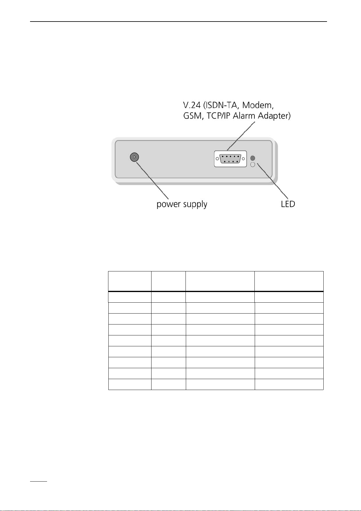
Front view CamLine
Modem RS-232
Interface
The pin assignment of the modem communications interface is compatible
with the IBM PC standard. It is equipped with all required control lines
through a 9 pin SUB-D plug and is reserved for the connection of a modem,
ISDN-TA, GSM interface or a TCP/IP Alarm Adapter. All control, configuration
and video data is transmitted through this interface.
Pin number Input/
Output Designation Abbreviation
1 Input Data Carrier Detect DCD
2 Input Receive Data RxD
3 Output Transmit Data TxD
4 Output Data Terminal Ready DTR
5 - Ground GND
6 Input Data Send Ready DSR
7 Output Ready to Send RTS
8 Input Clear to Send CTS
9 Input Ring Indicator RI

3 System Description
CamLine 13
Direct connection between CamLine and a PC
Null Modem cable
The CamTel®Windows Software and CamLine automatically recognise if a
null modem connection is being attempted. This is recognised on the basis of
a special code in the cable plug (pin assignment see below) which is read and
evaluated at the COM port when the device is switched on or when the Cam-
Tel®Windows Software is started. Please be certain only to use the original
null modem cable from HeiTel or an appropriately modified cable. No direct
connection is possible with standard commercial null modem cables.
Auto-baud recognition allows a connection at 115200 Baud, even when
CamLine is set to 230400 baud.
Pin Assignment of the HeiTel Null Modem Cable
Status information for CamLine
Display
The green LED indicates that the transmitter is switched on.
The yellow LED can signalize various conditions/errors by means of a se-
quence of flashes.
Conditions and
Errors
Off but flashes on for a short period = Offline
On but flashes off for a short period = Online
1 x flash everything is OK, transmitter is operational
2 x flash internal hardware fault
3 x flash same as 2x flash
4 x flash same as 2x flash
5 x flash connected modem / ISDN terminal adapter could not be addressed.
Check the connections and, when necessary, the dial prefix set in the trans-
mitter settings. You will also receive these errors when the transmitter is
switched on without a modem / ISDN terminal adapter or zero-modem cable
being connected. Normally, you should connect the modem / zero-modem
cable before switching on the device.
6x flash the receiver could not be reached by an alarm call. The reason for
this could be that the receiver program is not running or that the line is busy.
Ensure the null mode cable is connected to both PC and CamLine before ap-
plying power to the CamLine or starting the CamTel®Windowssoftware.
(3) (2)
(2) (3)
(7) (4)
(8) (5)
(5) (7)
(1) (6)
(4) (8)
(6) (20)
(1)
(4)
(6)
(2)
Tx Rx
(3)
Rx Tx
(8)
Rts Cts
(7)
Cts Rts
(5)
GND GND
DSR
DCD
DTR
9 pol. SUB-D 25 pol. SUB-D 9 pol. SUB-D
DSR
DTR
DCD
3 System Description
14 CamLine
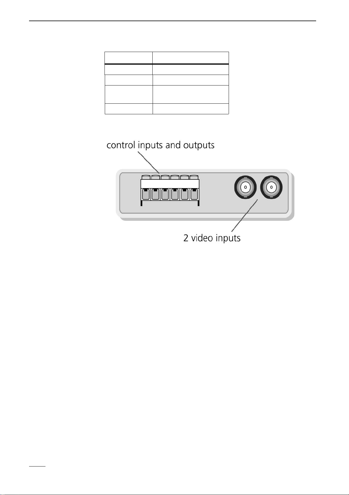
Rear View
Control Interface
All control inputs and outputs on the CamLine devices are realised in the form
of easily accessible screw/clamp connections.
The inputs are decoupled by means of capacitors to protect against faults and
are connected to ground (pin 3).
The settings menu is used to configure all inputs to the type of signal contacts
used. The device is compatible with signal contacts which have normaly open
or normaly closed contacts. The two camera signals allow CamLine to react
to signaling events triggered by external devices (such as door contacts, mo-
tion detectors, alarm system). When set, the transmitter box establishes a
connection with a CamLine receiver and transmits images from the respective
location.
Camera Signal
Save alarm image
If a camera alarm is activated, an image from the respective video input will
be saved. This is available as an alarm image in the event that a connection is
established and is transmitted as the first image.
Establishing a
connection
Each camera alarm can be set individually to establish a connection with the
receiver or not when it is activated.
Yellow LED Meaning
1x flash Unit is ready and armed
2 or 4 x flash Hardware fault
5x flash Modem/ISDN adapter
fault or line fault
6x flash Called party not available

3 System Description
CamLine 15
Display status
When online, the statuses of the camera alarm inputs are indicated by red
text in the camera buttons in the receiver software. This allows the user to
easily identify which cameras are sending signals at any given time.
Output (relay)
The transmitter box is equipped with a relay output for general switching pur-
poses. The relay can be configured in the software setup screen to be latching
or non latching switches.
When set as a latching switch, the relay state changes with each click on the
button (e.g. lighting on/off). When the relay is set as a non-latching switch,
the current relay status changes for the duration indicated in "Closed/s" (e.g.
for electro-magnetic door openers) each time the button is clicked.
There are two additional operating modes for the relay:
Switch on fault
A relay can be set as a fault relay to signal faults, such as failed connection
attempt. The relay is always active in release state when set as a fault relay,
so that power failures are also signalled (the relay breaks in the event of a
power failure).
Switch on
connection
In order to signal that CamLine is currently online, the relay switches on for
the duration of the connection and switches off at the end of the connection.
For example this function allows lights to be activated automatically in the ar-
ea being monitored. When set to "Switch on connection" the relay button
is deactivated on the CamLine receiver screen.
Loading the Factory
Settings
To load the factory settings, CamLine must first be connected to its own PC
using the nullmodem cable.
Then start the terminal software or Hyper Terminal from Microsoft. The ter-
minal program must be set to 115200 baud.
Now switch CamLine on. A "*" appears on the terminal screen. Enter
"cl-init"within 5 seconds. Shortly thereafter, "INIT OK" appears onthe
screen and the green LED goes off.
As soon as the green LED once more lights up, the factory settings are loaded.
Activations at the camera alarm must be for at least 1 second in order for
CamLine to recognise them properly.
Some relay settings do not take effect immediately, rather after the connec-
tion is terminated (e.g. deactivation of function Reset Offline).

3 System Description
16 CamLine
Pin assignment of the control interface
Inputs must be connected to ground (pin 3) by means of potential-free con-
tacts. The minimum contact time is 1 sec in order to ensure that switch con-
ditions are properly recognised.
Video Inputs
The two video inputs are BNC connections. A colour or monochrome signal
can be connected here. Almost all standard, commercially-available cameras
can be used, providing they correspond to the CCIR standard (PAL or NTSC).
75 Ohm
The impedance of the video input is set 75 Ohm (on).
Adjusting the video
signal
The picture quality should be checked at the receiver. The settings for bright-
ness and contrast can be adjusted at the receiver for each camera.
Pin Type Designation Short
des. Description
1 Input camera alarm 2 K2 Control input assigned
to camera 2
2 Input camera alarm 1 K1 Control input assigned
to camera 1
3 Ground Ground GND Physical ground
4 Output Relay 1 R1C Common contact relay 1
5 Output Relay 1 make con-
tact
R1S Make contact relay 1
6 Output Relay 1 break con-
tact
R1O Break contact from relay
1

3 System Description
CamLine 17
3.3 Installation and Setup Instructions
CamLine is designed for use under specific conditions. Conditions deviating
from these specifications may cause damage to your device and may invali-
date the guarantee. Please note the following operating conditions when us-
ing your CamLine equipment.
General Safety and Security Instructions
■Do not subject the device to strong vibrations or shocks.
■Avoid humid or dusty environments, extreme cold or heat and strong mag-
netic fields. CamLine can be operated between 0°C and 55°C ambient
temperature.
■Ensure adequate ventilation.
■Avoid extreme temperature variations.
■Never place the device in direct sunlight and keep it away from other heat
sources (heaters, etc.).
■Only use the original power supply unit with the intended network voltage
or ensure that the operating voltage does not exceed 14 V DC when using
a DC power supply.
■Select an installation site protected from theft and vandalism when using
your equipment for security purposes.
Electrical Safety
■Do not touch the CamLine device, power supply unit, cables
and plugs with wet hands.
■When disconnecting the device from the power supply, always
pull on the plug, never on the cable.
■If water or other liquids enter the device, immediately discon-
nect the power supply and have the device checked by cus-
tomer service.
■CamLine equipment may only be opened by authorised per-
sonnel.

3 System Description
18 CamLine

4 Connection of External Devices and Components
CamLine 19
4 Connection of External Devices and
Components
This chapter contains information on the use of external equipment with
CamLine. The use in transmission networks and the preparation of modems/
TAs is covered here.
4.1 Data transmission equipment
Suitable Transmission Networks
Image transmission with CamLine can be achieved via a number of transmis-
sion methods. The "modem" port serial interface available for connection to
transmission devices for ISDN, PSTN and GSM networks. Transmission over
Ethernet computer networks can easily be achieved by using the TCP/IP Alarm
Adapter, which acts as a transmission unit for Ethernet networks. Dedicated
connections can be established with dedicated line modems over simple two-
wire twisted pair copper lines, independent of public phone networks.
Interface Settings
Local Baud Rates
The local baud rate refers to the interface speeds of the serial interface be-
tween the modem/TA and CamLine (not to the transmission rate on the trans-
mission medium).
In most cases, e.g. for the transmission over ISDN lines or for null modem con-
nections directly to the PC, the setting 115200 baud is correct.
Exceptions must be made for:
■GSM transmissions with the Siemens Module M20 (19200 baud).
■Null modem connections to PC systems with COM ports that only support
57600 baud.
■Analogue connections with specific modems which must operate at 57600
baud.
Modem Settings
The highest degree of transmission security is achieved when the connected
transmission device (modem/TA, ...) is pre-configured on the PC. The device
can be pre-configured by means of a terminal program such as Hypertermi-
nal, which is included with the Win 95/98 operating systems. The required AT
command set is partially modem-specific and is described in any modem
manual. The following information applies to general modem configuration
for operation with CamLine. As supplementary information, the initialisation
strings are included for all devices which have been factory tested and are rec-
ommended. The list of usable devices is constantly updated and expanded.
Up-to-date overviews can be acquired from your specialised dealer.
Table of contents


