manuals.online logo
Brands
  1. Home
  2. •
  3. Brands
  4. •
  5. MG
  6. •
  7. Transmitter
  8. •
  9. MG Mini-M M2VF3 User manual

MG Mini-M M2VF3 User manual

EM-5107 Rev.5 P. 1 / 3
MG CO., LTD. www.mgco.jp
5-2-55 Minamitsumori, Nishinari-ku, Osaka 557-0063 JAPAN
INSTRUCTION MANUAL
Mini-M™
SIGNAL TRANSMITTER
(high-accuracy, ultra-high speed response 30 µsec.) MODEL M2VF3
BEFORE USE ....
Thank you for choosing us. Before use, please check con-
tents of the package you received as outlined below.
If you have any problems or questions with the product,
please contact our sales office or representatives.
■PACKAGE INCLUDES:
Signal conditioner (body + base socket).............................(1)
■MODEL NO.
Confirm Model No. marking on the product to be exactly
what you ordered.
■INSTRUCTION MANUAL
This manual describes necessary points of caution when
you use this product, including installation, connection and
basic maintenance procedures.
POINTS OF CAUTION
■CONFORMITY WITH EU DIRECTIVES OR UK LEGISLATION
• The equipment must be mounted inside a panel.
• The actual installation environments such as panel con-
figurations, connected devices, connected wires, may affect
the protection level of this unit when it is integrated in a
panel system. The user may have to review the CE/UKCA
requirements in regard to the whole system and employ
additional protective measures* to ensure the CE/UKCA
conformity.
* For example, installation of noise filters and clamp fil-
ters for the power source, input and output connected
to the unit, etc.
• Install lightning surge protectors for those wires connect-
ed to remote locations.
• Cover the cables (power supply, input and output) using
Shield tubes in order to prevent external noise inter-
ference. (We recommend Nitto Electric Works Co.,Ltd
“MTF-ES Series” products or equivalent.)
■POWER INPUT RATING & OPERATIONAL RANGE
• Locate the power input rating marked on the product and
confirm its operational range as indicated below:
24V DC rating: 24V ±10%, ≤ 0.6W
■GENERAL PRECAUTIONS
• Before you remove the unit from its base socket or mount
it, turn off the power supply and input signal for safety.
■ENVIRONMENT
• Indoor use.
• When heavy dust or metal particles are present in the
air, install the unit inside proper housing with sufficient
ventilation.
• Do not install the unit where it is subjected to continuous
vibration. Do not subject the unit to physical impact.
• Environmental temperature must be within -5 to +55°C
(23 to 131°F) with relative humidity within 30 to 90% RH
in order to ensure adequate life span and operation.
• Be sure that the ventilation slits are not covered with ca-
bles, etc.
■WIRING
• Do not install cables close to noise sources (relay drive
cable, high frequency line, etc.).
• Do not bind these cables together with those in which
noises are present. Do not install them in the same duct.
■AND ....
• The unit is designed to function as soon as power is sup-
plied, however, a warm up for 10 minutes is required for
satisfying complete performance described in the data
sheet.
• Do not leave the output terminals short-circuited for
a long time. The unit is designed to endure it without
breakdown, however, it may shorten appropriate life du-
ration.
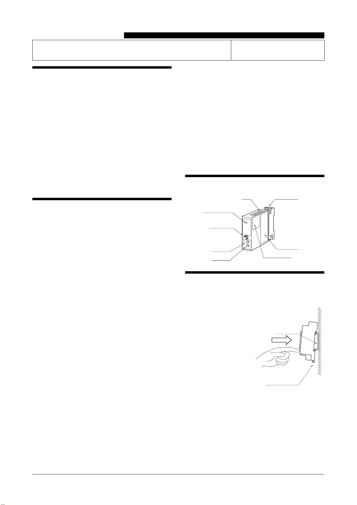
COMPONENT IDENTIFICATION
Model
SPAN
ZERO
Zero Adj.
Span Adj.
Body Base Socket
Connection
Diagram
Specifications
Fixing Screw
Power LED
INSTALLATION
Loosen the fixing screw at the front of the unit in order to
separate the body from the base socket.
DIN Rail
35mm wide
Spring Loaded
DIN Rail Adaptor
■DIN RAIL MOUNTING
Set the base socket so that
its DIN rail adaptor is at
the bottom. Position the
upper hook at the rear side
of base socket on the DIN
rail and push in the lower.
When removing the socket,
push down the DIN rail
adaptor utilizing a minus
screwdriver and pull.
■WALL MOUNTING
Refer to “EXTERNAL DIMENSIONS.”
M2VF3
EM-5107 Rev.5 P. 2 / 3
MG CO., LTD. www.mgco.jp
5-2-55 Minamitsumori, Nishinari-ku, Osaka 557-0063 JAPAN
TERMINAL CONNECTIONS
Connect the unit as in the diagram below or refer to the connection diagram on the side of the unit.
■EXTERNAL DIMENSIONS unit: mm (inch)
5
9
21.5 (.85)
70.5 (2.78)
84 (3.31)10 (.39) 15 (.59)
6 (.23)
59 (2.32)
DIN RAIL
35mm wide
[4 (.16)]
8–M3
SCREW
72 (2.83)
23 (.91)
2–4.2x5
(.17x.20)
MTG HOLE
6 (.24) deep
114 (4.49)
• When mounting, no extra space is needed between units.
4
8
12
14 13
1
4 (.16)
■CONNECTION DIAGRAM
1
4
9
12
13
14
8
4
9
12
13
14
+
–
+
–
+
–
+
–
+
–
+
–
SIGNAL SOURCE
SIGNAL SOURCE
OUTPUT
POWER
POWER
OUTPUT
• At input signal code "0", signal source is allocated between
terminals 8 and 4 when input exceeds 300V.
The M2VF3, by its fast-response feature, is not designed to eliminate
noise present in the input signal. Use a shielded twisted-pair cable
to prevent noise from entering through the input wiring.
WIRING INSTRUCTIONS
■SCREW TERMINAL
Torque: 0.8 N·m
■SOLDERLESS TERMINAL
Refer to the drawing below for recommended ring tongue
terminal size. Spade tongue type is also applicable.
Applicable wire size: 0.25 to 1.65 mm2(AWG 22 to 16)
Recommended manufacturer: Japan Solderless Terminal
MFG.Co.Ltd, Nichifu Co.,ltd
6 (.24) max
3.3 (.13) max
mm (inch)
M2VF3
EM-5107 Rev.5 P. 3 / 3
MG CO., LTD. www.mgco.jp
5-2-55 Minamitsumori, Nishinari-ku, Osaka 557-0063 JAPAN
CHECKING
1) Terminal wiring: Check that all cables are correctly con-
nected according to the connection diagram.
2) Power input voltage: Check voltage across the terminal
13 – 14 with a multimeter.
3) Input: Check that the input signal is within 0 – 100% of
the full-scale.
4) Output: Check that the load resistance meets the de-
scribed specifications.
ADJUSTMENT PROCEDURE
This unit is calibrated at the factory to meet the ordered
specifications, therefore you usually do not need any cali-
bration.
For matching the signal to a receiving instrument or in case
of regular calibration, adjust the output as explained in the
following.
■HOW TO CALIBRATE THE OUTPUT SIGNAL
Use a signal source and measuring instruments of sufficient
accuracy level. Turn the power supply on and warm up for
more than 10 minutes.
1) ZERO: Apply 50% input and adjust output to 50%.
2) SPAN: Apply 100% input and adjust output to 100%.
3) Check ZERO adjustment again with 0% input.
4) When ZERO value is changed perform fine adjustment
with ZERO as output: (0% – 100%) / 2.
5) SPAN: Apply 100% input and adjust output to 100%
MAINTENANCE
Regular calibration procedure is explained below:
■CALIBRATION
Warm up the unit for at least 10 minutes. Apply 0%, 25%,
50%, 75% and 100% input signal. Check that the output
signal for the respective input signal remains within accu-
racy described in the data sheet. When the output is out of
tolerance, recalibrate the unit according to the “ADJUST-
MENT PROCEDURE” explained earlier.
LIGHTNING SURGE PROTECTION
We offer a series of lightning surge protector for protec-
tion against induced lightning surges. Please contact us to
choose appropriate models.

Other MG Transmitter manuals

MG W5LCS User manual

MG

MG W5LCS User manual

MG HR User manual

MG

MG HR User manual

MG 10JRE User manual

MG

MG 10JRE User manual

MG M3SVS User manual

MG

MG M3SVS User manual

MG SVF User manual

MG

MG SVF User manual

MG 10AC User manual

MG

MG 10AC User manual

MG M6SWVS User manual

MG

MG M6SWVS User manual

MG M6NWVS User manual

MG

MG M6NWVS User manual

MG M3-UNIT Series User manual

MG

MG M3-UNIT Series User manual

MG M6NVF User manual

MG

MG M6NVF User manual

MG BCT User manual

MG

MG BCT User manual

MG BR User manual

MG

MG BR User manual

MG B5MS User manual

MG

MG B5MS User manual

MG M6DCTC User manual

MG

MG M6DCTC User manual

MG Mini-M M2EXV User manual

MG

MG Mini-M M2EXV User manual

MG Mini-M M2TS User manual

MG

MG Mini-M M2TS User manual

MG FRT User manual

MG

MG FRT User manual

MG KWRS2 User manual

MG

MG KWRS2 User manual

MG M6SXM User manual

MG

MG M6SXM User manual

MG M6NPA User manual

MG

MG M6NPA User manual

MG W5VS User manual

MG

MG W5VS User manual

MG 18JPA User manual

MG

MG 18JPA User manual

MG 10MS User manual

MG

MG 10MS User manual

MG 17PE User manual

MG

MG 17PE User manual

Popular Transmitter manuals by other brands

DAPAudio EB-16 manual

DAPAudio

DAPAudio EB-16 manual

YOKOGAWA DpharpEJX vigilantplant EJX210A user manual

YOKOGAWA

YOKOGAWA DpharpEJX vigilantplant EJX210A user manual

Erreka IRIS IR02 quick start guide

Erreka

Erreka IRIS IR02 quick start guide

Erreka KUMA KU02 instructions

Erreka

Erreka KUMA KU02 instructions

Telefunken TF-FMT32BT instruction manual

Telefunken

Telefunken TF-FMT32BT instruction manual

Thies CLIMA 5.4103.10.000 Instructions for use

Thies CLIMA

Thies CLIMA 5.4103.10.000 Instructions for use

GESTRA TRV 5-40 installation instructions

GESTRA

GESTRA TRV 5-40 installation instructions

REL 518-D instruction manual

REL

REL 518-D instruction manual

Moore Industries STZ user manual

Moore Industries

Moore Industries STZ user manual

Data Video HBT-15 instruction manual

Data Video

Data Video HBT-15 instruction manual

impact VC-500WLXMT instructions

impact

impact VC-500WLXMT instructions

Technalogix TAUD-1000 Operation manual

Technalogix

Technalogix TAUD-1000 Operation manual

Ametek Drexelbrook Universal Lite 509-1 Series Installation and operating instructions

Ametek Drexelbrook

Ametek Drexelbrook Universal Lite 509-1 Series Installation and operating instructions

Intercoax Ipify ECP-2704R-4T-PKG Quick install guide

Intercoax

Intercoax Ipify ECP-2704R-4T-PKG Quick install guide

Great Lakes Instruments 692P manual

Great Lakes Instruments

Great Lakes Instruments 692P manual

PureTools PT-HDBT-100P-TX user manual

PureTools

PureTools PT-HDBT-100P-TX user manual

Acromag 655T-06003-C user manual

Acromag

Acromag 655T-06003-C user manual

Teledyne Analytical Instruments INSTA TRANS-XD operating instructions

Teledyne Analytical Instruments

Teledyne Analytical Instruments INSTA TRANS-XD operating instructions

manuals.online logo
manuals.online logoBrands
  • About & Mission
  • Contact us
  • Privacy Policy
  • Terms and Conditions

Copyright 2025 Manuals.Online. All Rights Reserved.