Amphony Model 400 Manual

R
User and Installation Guide
Multi Channel Audio Transmitter
5.8 GHz
Model 400

Contents
Unpacking
Connecting the transmitter
Placing the transmitter
Operating the transmitter
Troubleshooting
Technical specifications
Safety information
Limited Warranty
................................................................................. 3
........................................................ 3
............................................................... 6
........................................................... 6
......................................................................... 7
............................................................. 9
................................................................... 10
..................................................................... 12

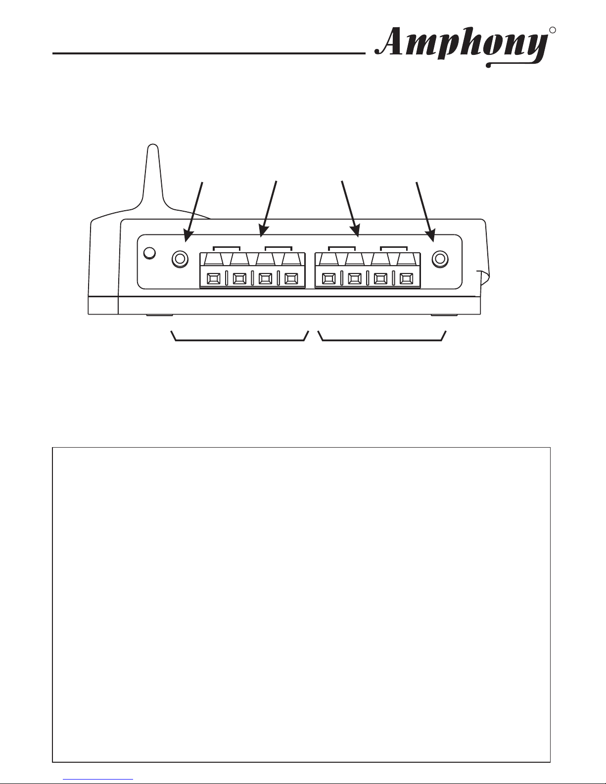
Step 1 Connecting the transmitter
The transmitter has two stereo audio inputs, one zone-A and one zone-B input.
4 audio channels can be transmitted simultaneously. Both zone-A and zone-B audio
inputs can connect either to an unbalanced line-level audio output or a balanced
amplified speaker output. For best audio quality, we recommend using the
unbalanced line-level audio input.
The transmitter can transmit to Model 400 wireless audio receivers and Model 480
wireless amplifiers. Each audio channel is encoded with a channel ID and can be
selected by each wireless receiver.
Regardless of whether any specific audio channel is transmitted to a wireless
receiver or wireless amplifier, both the transmitter line-level and amplified speaker
audio inputs can be used to feed audio into the transmitter.
Connect the transmitter to an unbalanced audio input by using the supplied phone-
RCA audio cable. Connect the phone jack with the line level input of the transmitter
and the RCA jack with the RCA output of your audio source.
Alternatively, connect the transmitter to an amplified speaker output by using the
supplied speaker cables. Be sure to observe the correct polarity of the speaker
cable.
Note:
If one of the speaker cables is switched (reversed), one speaker will receive
an opposite polarity signal which will degrade sound performance.
It is possible to connect zone-A audio inputs to line-level audio outputs and zone-B
audio inputs to amplified speaker outputs and vice versa. However, only the
unbalanced line level input or speaker inputs of each zone can be used, i.e. you
cannot mix audio inputs within a zone.
Connect the supplied small AC adapter’s barrel-shaped plug into the DC 9V jack,
and then plug the transformer into a standard AC outlet. We recommend the use of
a surge protector to protect the transmitter from power surges.
Unpacking: Check that this package contains:
One 5.8 GHz Digital Audio transmitter - Model 400, one 9 V AC adapter (wallwart),
four short speaker cables, two RCA audio cables.
ATTENTION!
Do not connect both the line level audio input and amplified speaker
audio input of the same zone. This may damage your audio source.
User and Installation Guide
R
Page 3

User and Installation Guide
R
LR LR
LINE
IN A
LINE
IN B
AB
DC
9V
Zone A Inputs Zone B Inputs
Line level
input A
Line level
input B
Amplified
speaker inputs
Copyright (C) 2010 Amphony. All rights reserved.
The information contained herein is subject to change without notice.
Revisions may be issued to advise of such changes and/or additions.
All product names, trade names, or corporate names mentioned in this
document are acknowledged to be the proprietary property of the
registered owners.
This device complies with part 15 of the FCC Rules. Operation is
subjected to the following two conditions: 1) This device may not cause
harmful interference and 2) this device must accept any interference
received, including interference that may cause undesired operation.
FCC ID PMJT400
Caution: Any changes or modifications not expressly approved by the
party responsible for compliance could void the user's authority to
operate the equipment.
Transmitter audio inputs

User and Installation Guide
R
LR LR
LINE
IN A
LINE
IN B
AB
DC
9V
LR
SPEAKER OUT
Audio Source
LR
Example: Using the amplified Zone-A speaker inputs and Zone-B line
level audio input
LINE OUT
DC 9 V
Power outlet
AC adapter
Page 5

User and Installation Guide
R
Step 2 Placing the transmitter
Ideally, the transmitter should be placed at an elevation such that there
are no obstacles between the transmitter and wireless receivers or
amplifiers (line of sight) in an area where there will be the least amount
of traffic. We suggest that you place the transmitter on top of your audio
source.
Step 3 Operating the transmitter
The green transmit light of the transmitter will be on when audio is
transmitted.
If you are using the speaker outputs, adjust the audio level of your audio
source to the maximum level where no clipping / distortion occurs at the
wireless receivers.
If the audio level supplied to the transmitter is too high, then distortion
will occur. If the audio level is too low, the dynamic range of the
transmission will not be used and the audio level at the receiver may be
too low.
If you are using a line-level audio output and the audio level is too low,
try instead using an audio output with audio volume regulator such as a
headphone output. The transmitter can connect to a headphone output
by using a phone jack-to-phone jack cable.
If audio reception is poor, try raising the transmitter and changing the
transmitter location until reception is acceptable.
If no audio signal is present, the transmitter will go into standby mode
after approximately two minutes. The transmitter will wake up as soon as
an audio signal is present.
Page 6

Troubleshooting
Problem Possible Cause Solution
Th e tr ans mit lig ht
d oes n o t go on af ter
DC pow er is ap plied
to the transmit ter
Faulty AC a d apter
or faultypower outlet
Check the power outlet and the
AC a da pt er; if poss ible , ch eck f or
correct voltage of the ACadapter.
Th e tr ans mit lig ht
g oes o u t aft er a f ew
seco nds an d doe s
not light again
No audio pr e sen t a t
au dio inp u t
Check the audio connection to
th e tran smit te r and en sure th at
th ere is aud io pr es e nt.
Transmitter hung up Disconnect and then reconnect
DC powe r.
No a ud io a t recei ver Faulty AC a d apter
or faultypower outlet
Ch e ck th e r ece iver po wer su pply .
St ro ng in t er f er enc e Se e u nd e r “Stron g Int erf ere nce“
on next page.
Au dio is dis t ort ed Au dio v olume t oo
high
Adjust th e transmitt er volu me
control until clipping stops.
Amplifier volume
control set too high
L ower th e s ource a udio volum e
un til cli pping st ops .
St ro ng in t er f er enc e Se e u nd e r “Stron g Int erf ere nce“
on next page.
Rece ive r au dio level
is too low
Au dio v olume t oo low Raise t h e sou rce aud io volume t o
achieve the desired audio level.
Connect transmitter to an
ad ju st able au dio out pu t
Amplifier volume
control set too low
Adjust the amplifier vol ume
control toachievedesired audio
level.
Au dio d rop s out
inter mittently or
crackles
St ro ng in t er f er enc e Se e u nd e r “Stron g Int erf ere nce“
on next page.
Un sta ble power
sup ply / p owe r surges
En sure t h at t he p o we r ou tlet
delivers a stable voltage. Very
stron g su r ges or vo ltag e
f luc tu at io n s ma y ca use au dio
dr opou ts. Tr y u sing a s urg e
pr ot ect or.
User and Installation Guide
R
Page 7

User and Installation Guide
R
For up-to-date troubleshooting advice, visit www.amphony.com
Problem Possible Cause Solution
Tra n sm itt er range is
extremelyshort
St ro ng in t er f er enc e In so me cas es , t here ma y be
strong interference preventing
pr oper r ec ept io n of t he a udio
signal which can be caused by
5.8 GHz cordless telephones or
5. 8 G Hz wire less n et wor ks . E ither
elimin ate the in te rf erenc e, loc at e
the base unit of the cordless
ph on e in an o ther ro om, set th e
wi reless network to use the 5.1
GHz frequency band rather than
5. 8 G Hz , reloc ate th e t ra nsmitter ,
relocate or reorient the amplifier
t o im prove re cept io n.
Too manyobstacles Audio will drop out if there are too
many ob stacle s bet ween t h e
trans mitt er an d the rec eive r, t r y
reloc ating the tr ans mitt er or
recei ver to i mpr ove rec ept ion.
Page 8

User and Installation Guide
R
Technical Specifications:
Transmitter frequency: 5.8 GHz
Audio transmission: Digital
Number of wireless audio channels: 4
Automatic power-down feature
Operating range:
-max. 150 ft line of sight
- max. 30 ft through walls and obstacles
Compatible wireless receivers:
- Model 400 wireless audio receiver
- Model 480 wireless audio amplifier
Audio inputs:
- 4 x speaker-level input
- 2 x stereo line-level input
Signal-to-noise ratio: typ. 96 dB (A-weighted)
Frequency response: 2 Hz - 20 kHz
Audio latency: < 1 ms
Total harmonic distortion: -90 dB (0.003%)
Transmitted data rate: 6 Mbps
Error correction: 1/2 rate FEC
Channel separation: 95 dB
Audio input level: max. 3 Vrms
Page 9

User and Installation Guide
R
READ THESE SAFETY INSTRUCTIONS CAREFULLY AND
HEED ALL WARNINGS IN THIS MANUAL.
POWER SOURCE
To product malfunction, and to protect against electric shock, fire or
personal injury, please observe the following:
• This product has been designed to work with 120-volt AC current using
the supplied AC adapters. Connection to a line voltage other than that or
use of non-compatible AC adapters may create a safety and fire hazard
and may damage the product.
• Do not run power cords under rugs or carpets or place heavy objects on
them.
• Damaged or deformed power cords are hazardous and should be
replaced immediately by a qualified service technician.
LOCATION
• Do not place this product in direct sunlight, or near heat sources.
• Keep this product away from strong magnetic objects.
CARE
• Do not place any object containing water or other liquids on this product.
• Do not remove the cabinet. Touching parts inside the cabinet could result
in electric shock and damage to the product.
• Do not use this product outdoors or in cars.
VOLUME CONTROL
• Do not turn up the amplifier volume while listening to a portion with very
low level input or no audio signal to avoid damage to your speakers
during a peak level audio portion.
• Turn the amplifier volume control to minimum prior to connecting or
disconnecting the transmitter or amplifier and prior to switching audio
sources as this may cause loud clicks which can damage your speakers.
NON-USE PERIODS
• When the product is not being used for a long period of time, unplug the
product.
IMPORTANT SAFETY INFORMATION ATTENTION!
Page 10

User and Installation Guide
R
CLEANING
• Unplug the product before cleaning.
• When the system gets dirty, wipe it with a clean, soft cloth. If necessary,
wipe it with a soft cloth, slightly dampened with soapy water. Wipe dry
immediately with a dry cloth.
• Never use benzene, aerosol cleaners, thinner, alcohol or any volatile
cleaning agent.
• Do not use abrasive cleaners, as they may damage the finish.
SERVICE
• Do not open the cabinet of any components. Opening the cabinets may
present a shock hazard, and any modification to this product will void
your warranty.
• Do not attempt to service the unit yourself.
• Please refer any service to an authorized Amphony service center.
Page 11

User and Installation Guide
R
Limited warranty
WHAT YOUR WARRANTY COVERS
This warranty extends only to the original user of the equipment (“you”, ”your”)
and is limited to the purchase price of each part. Amphony and its affiliated
companies (”we”, ”our”, ”us”) warrant this Multi Channel Audio Transmitter
against defects in materials or workmanship as follows.
For a period of ninety (90) days from the original date of purchase, if
we determine that the equipment is defective subject to the limitations of this
warranty, we will replace it at no charge for labor. We warrant any such work
done against defects in materials or workmanship for the remaining portion of
the original warranty period.
For a period of one (1) year from the original date of purchase, we will
supply, at no charge, new or rebuilt replacement parts in exchange for parts we
determine are defective subject to the limitations of this warranty. We warrant
any such replacement parts against defects in materials or workmanship for
the remaining portion of the original warranty period.
”Parts” means items included in this package. It does include other
parts purchased separately.
LABOR:
PARTS:
Note: not
WHAT YOUR WARRANTY DOES NOT COVER
This warranty consumer instruction, physical setup or
adjustment of any consumer electronic equipment, or signal transmission
problems.
This warranty cosmetic damage, damage due to the affixing of
any attachment not provided with the product, loss of parts, connecting the
product to any but the specified receptacles, lightning, electrical surges, fire,
flood, or other acts of God, accident, misuse, abuse, repair or alteration by
other than authorized service personnel, negligence, commercial or institutional
use, or improper or neglected maintenance.
This warranty equipment sold AS IS or WITH ALL FAULTS,
equipment removal or reinstallation, shipping damage if the equipment was not
packed and shipped in the manner we prescribe, nor equipment purchased,
serviced, or operated outside the contiguous United States of America.
does not cover
does not cover
does not cover
Page 12

LEGAL LIMITATIONS
REPLACEMENT AS PROVIDED UNDER THIS WARRANTY IS YOUR
EXCLUSIVE REMEDY. WE SHALL NOT BE HELD LIABLE FOR ANY
INCIDENTAL OR CONSEQUENTIAL DAMAGES FOR BREACH OF ANY
EXPRESSED OR IMPLIED WARRANTY ON THIS EQUIPMENT, NOR FOR
ANY INCIDENTAL OR CONSEQUENTIAL DAMAGES RESULTING FROM
THE USE OF, OR INABILITY TO USE, THIS EQUIPMENT. UNDER NO
CIRCUMSTANCES SHALL OUR LIABILITY, IF ANY, EXCEED THE
PURCHASE PRICE PAID FOR THIS EQUIPMENT, EXCEPT TO THE
EXTENT PROHIBITED BY APPLICABLE LAW. EXCEPT AS PROVIDED
HEREIN, WE MAKE NO WARRANTIES, EXPRESS OR IMPLIED,
INCLUDING WARRANTIES OF MERCHANTABILITY AND FITNESS FOR A
PARTICULAR PURPOSE. WE RESERVE THE RIGHT TO REFUSE TO
HONOR THIS WARRANTY IF WE DETERMINE ANY OF THE ABOVE
EXCEPTIONS TO HAVE CAUSED THIS EQUIPMENT NOT TO HAVE
PERFORMED PROPERLY. THIS WARRANTY SHALL BE VOID IF ANY
FACTORY-APPLIED IDENTIFICATION MARK, INCLUDING BUT NOT
LIMITED TO SERIAL NUMBERS AND WARRANTY LABELS, HAS BEEN
ALTERED OR REMOVED. THIS WARRANTY SHALL ALSO BE VOID IF THE
TRANSMITTER OR AMPLIFIER HAVE BEEN OPENED BY AN
UNAUTHORIZED PERSON.
This warranty gives you specific legal rights which may vary from state to state.
Some states do not allow the exclusion or limitation of incidental or
consequential damages, or allow limitations on the duration of an implied
warranty, so those limitations may not apply to you.
No responsibility is assumed for the presence of interference outside of
Amphony’s control, such as other transmitters or cordless phones, which may
hamper proper signal reception.
Note:
User and Installation Guide
R
Table of contents
Other Amphony Transmitter manuals