Heli-Professional REVOLUTION 500E User manual

REVOLUTION 500E RTF
Manual v
1.0
CONTENTS
Page
Introduction
2
Product Contents
2
Specifications
3
General Safety Instructions
3
Flight Battery Safety Instructions
3-4
Checklist Maiden Flight
4
Checklist Regular Flights
4-5
Charging the Flight Battery
5
Insert the Batteries in the Transmitter
6
Inserting the Flight Battery
6
Transmitter Settings
6-9
Control Test
9-12
Control Functions During Flights
13-16
Preparing the Maiden Flight
17
Adjusting the Rotor Blade Tracking
17
Manual Xelaris 80A Brushless ESC
18-19
Assembly instructions Revolution 500E
21-40
©Heli-Professional 2012

www.heli-professional.com
2
Dear
Customer,
thank you for choosing the
Revolution 500E RTF helicopter.
PLEASE READ THIS MANUAL CAREFULLY BEFORE THE INITIAL STARTUP.
The Revolution 500E Ready To Fly is a high performance model helicopter that was specifically designed for beginners
with sufficient experience of pitch-controlled models. The helicopter is completely assembled, tested and ready for
use. The model is equipped with high-quality RC components. Besides a 4S 4250mAh lithium polymer battery, digital
servos, a brushless motor, a 2.4 GHz transmitter with receiver and the Xelaris Flybarless-3X System (FBL-3X) are in-
cluded.
Due to its various settings, the model is extremely versatile and offers setups for the individual needs of every pilot.
Since piloting a remote controlled model helicopter is very complex, we strongly recommend taking model helicopter
flight lessons or using a flight simulator when you are a beginner.
Although the Revolution 500E is a Ready To Fly model, we also strongly recommend to read this manual carefully.
Please don’t hesitate to contact your local dealer if you have any questions.
Product Contents
Revolution 500E RTF
FBL
-3X flybarless system
520mm GFK
main rotor blades
Digital swash plate and tail rotor servos with plastic
gearing
85mm
tail rotor blades
4S 4250mAh
battery
Bicolor plastic canopy
X
-4DC charger
4S 1300kv
brushless motor
2.4GHz
Transmitter and receiver
4S LiPo Brushless
ESC

www.heli-professional.com
3
Specifications
Main rotor diameter
:
approx
. 1200 mm
Take
-off weight:
approx
. 2800 g
Height
:
approx
. 340 mm
Length
:
approx
. 1100 mm
Tail rotor diameter
:
approx
. 235 mm
LiPo
battery:
4S 4250 mAh
General Safety Instructions
A model helicopter is a very powerful flying device and not a toy. Disregarding our instructions, inappropriate use,
and insufficient maintenance by persons lacking necessary competence may result in injuries for the user and can
cause damage to the surroundings and to materials. Therefore, we strongly recommend to get insurance. Children
and juveniles should operate a model helicopter only under supervision of an experienced adult.
Make sure that all necessary batteries for regular flights are fully charged. Do not fly on public roads, in residential
areas or close to people. Contact with rotating blades can cause severe injuries or even death.
Heli Professional will not accept responsibility for any damage caused by products of the delivery program and
rejects any liability, as we are not in a position to supervise proper operation, handling, and maintenance by the
user. Furthermore, we ask you to follow our operating instructions carefully and to use only original Heli Profes-
sional parts.
Flight Battery Safety Instructions
Inappropriate use can cause lithium polymer batteries to burn, explode, and release toxic gas which
can cause severe burns and poisoning.
Heli Professional will not accept responsibility for any damage caused by inappropriate use and rejects
any liability, as we are not in a position to supervise proper operation, handling, and maintenance. You are also
obliged to comply to the safety regulations in dealing with lithium polymer batteries. If you disagree with these
safety regulations, we kindly ask you to return the helicopter boxed as new and in unused condition to your dealer.
·Charge and store the battery ALWAYS in a non-flammable environment resp. in a fireproof container (e.g. LiPo-
bag), which prevents a flashover in case of a battery ignition.
·Never charge the battery unattended.
·The battery must always be charged outside the helicopter model. Therefore, remove the battery including the
battery plate from the model.
·Only use the battery in combination with the included charger. Other uses are prohibited.
·Always store the battery in a dry and dark environment at room temperature. Never expose the battery to direct
insolation or intense heat. When transporting the battery, the temperature must be between +10°C and +35°C.
Never store the battery in your vehicle as it may catch fire or explode due to heat development in the interior.
·Should the battery bloat during the charging or discharging process, disconnect the charger or the ESC immedi-
ately from the battery. Danger of fire! A bloated battery can never be used again and must be disposed properly.
·In case of a crash: Disconnect the battery as fast as possible from the ESC. Make sure the battery doesn’t bloat
and check it for mechanical damages. Store the battery in a LiPo-bag or outside. The battery can still catch fire
even after several hours.
·Keep the battery away from children and unauthorized persons.
·Let the battery cool down after each flight and before every charge.

www.heli-professional.com
4
·The battery must neither be overcharged nor exhausted. The battery is totally damaged and cannot be used an-
ymore in case of an exhaustive discharge. Therefore do not exceed following flight times:
Flight Style
3D Mode
Max. Flight Time*
Hover
Off
6.5 Minutes
Basic Flight
Off
5.5 Minutes
Aerobatics
On
4 Minutes
* Please note: the max. flight time will be shorter in cold condition or with old batteries.
·Heli Professional will not accept responsibility for any damage or secondary failures caused by inappropriate use
and rejects any liability, as we are not in a position to supervise proper operation, handling, and maintenance.
Checklist Maiden Flight
Attention: This checklist is supposed to give you a short overview of the preparations for the maiden flight and does
not replace the contents of this manual.
·Unbox and check all parts for damage.
·Check if all screws are fully tighten
·Check if all connectors are plugged in securely
·The main blade screws must be tightened until the blades can only be moved with a lot of force
·Charge the battery with the included charger according to the instructions. Notice the safety instructions and pay
attention to the correct polarity of the charger, the balancer and the ESC of the model.
·Insert AA batteries into the Transmitter. Do not change the settings of the transmitter in any way!
·Position and tighten the fully charged battery according to the picture on the battery plate with the included
hook and loop fasteners and secure it with O-rings in the helicopter model.
·Secure the balancer plug under the hook and loop fastener according to the picture.
·Test all functions of the model. The FBL-3X system and the transmitter are already programmed. No further set-
tings are required.
·The initial startup should be done on an appropriate airfield. Local clubs generally offer the best possibilities for
safe and fun helicopter flying.
Checklist Regular Flights
Attention: This checklist is supposed to give you a short overview of regular flights and does not replace the contents
of this manual.
·Check all connections and screws before every flight
·Secure the battery with O-rings in the battery rails and connect the ESC with the battery.

www.heli-professional.com
5
·To avoid the main blades from fold together when starting or landing, the main blade screws must be tighten
very hard, so that the blades can only be moved with a lot of force. If the main blades fold together, they start an
extreme vibration which can destroy the helicopter! If this happens, due to less tightened main blade screws, it
can be stopped by pushing the pitch stick hard and fast to positive pitch (Motor must be cut off!). If you do this,
you can avoid the helicopter from destroying itself.
·Always switch on the transmitter first! Throttle/pitch stick and other switches must be set on their zero position
beforehand!
·Wait until the ESC and the FBL-3X system have initialized. The FBL-3X system has initialized when the swash plate
has rotated once. The helicopter must stand absolutely still and leveled during this procedure.
·Check the function of all servos (direction of movement, etc.). Therefore, put the autorotation switch in the po-
sition “lock”. This prevents the motor from running unintendedly.
·Fly with your model.
·Start the landing procedure before the battery is low.
·Disconnect the ESC from the battery and switch off the transmitter finally.
Charging the Flight Battery
Charge the 4S 4250mAh lithium polymer battery only with the included charger, which is optimally
adjusted to charge and balance the battery. Disregarding this procedure may cause damage to the bat-
tery, the charger and the immediate environment (danger of fire). Never charge the battery unattended!
We recommend to charge and store the battery in a non-flammable environment (e.g. LiPo-bag). Pay attention to
the correct polarity when connecting the charger and the balancers with the battery.
Power supply:
·12V car battery: Use a 12V lead gel battery to connect directly to the charger (no power adaptor necessary).
·230V power supply: Use the charger only with an appropriate power adaptor (Not included. Ord. no. 01.1378
and 01.1376).
Charging the battery:
1. Disconnect the battery from the ESC and remove the battery with the battery plate from the model.
2. Connect the charger first with the 12V power supply. All LEDs must blink red and green.
3. Now connect the battery with the charger and the balancer plug of the battery with the balancer socket of the
charger according to the picture. The LEDs are blinking red.
4. Choose the charging current with the knob (recommendation: 4.5A).
5. Press the start button. All LEDs must glow red.
6. When the charging is finished, you will hear a whistling sound and all LEDs must glow green.
7. Disconnect the battery from the charger and disconnect the charger from the power supply.

www.heli-professional.com
6
Insert the Batteries in the Transmitter
Insert 8 AA batteries (not included) into the 2.4 GHz transmitter. Pay attention to the correct polarity. Check the pow-
er level of the batteries on the voltage display. Change the batteries immediately when the voltage is too low and the
acoustic warning signal sounds.
Inserting the flight battery
Slide the battery plate including the flight battery into the battery rails of the front porch and secure it with O-rings.
Sliding in the battery plate. Securing the battery plate with O-rings.
Transmitter settings
Do not change any settings or the programming of the transmitter. All settings are optimally configured ex works.
Any changes whatsoever are at your own risk. Heli Professional will not accept responsibility for damages or any
secondary failures.
Two throttle curves are programmed ex works: a hovering/normal flight curve (switch position “Normal”) and a
3D/stunt flight curve (switch position “3D”).
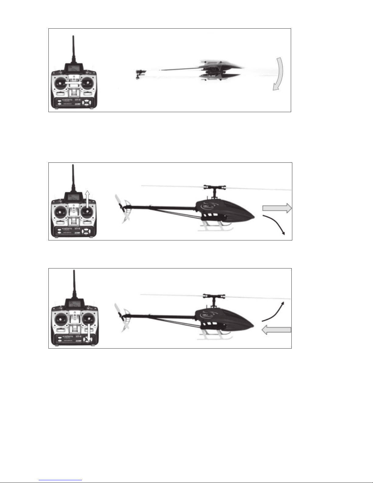
Hovering/Normal Flight Mode (Pitch Range -5°/+12°): When switching
on the transmitter or starting the model, always put the pitch stick in
its lowest position. If you tilt the pitch stick slowly upwards, the collec-
tive pitch angle of the main blades will increase, and the helicopter will
start to climb. If you lower the pitch stick, the collective pitch angle of
the main blades will decrease and the helicopter will start to descent.

www.heli-professional.com
7
Never change the stick positions of the aileron, elevator and rudder stick while the helicopter lifts off! You are only
allowed to actually pilot the helicopter after it has lifted off from the ground completely. Otherwise, the gyro stabi-
lizer system can be interfered.
3D/Stunt Flight Mode (Pitch Range -12°/+12°): In contrast to the hovering/normal flight mode, the maximum nega-
tive pitch range is -12°. This means that you have a collective pitch angle of 0°in the mid-position of the pitch stick. So,
when switching on the transmitter or starting the model, always put the pitch stick in a position some degrees below
the mid-position. If you tilt the pitch stick slowly upwards, the collective pitch angle of the main blades will increase,
and the helicopter will start to climb. If you lower the pitch stick towards the mid-position, the collective pitch angle of
the main blades will decrease and the helicopter will start to descent. If you lower the pitch stick below the mid-
position, the collective pitch angle of the main blades (in the negative direction) will increase again and you are able to
fly loops, rolls and 3D maneuvers.
Never change the stick positions of the aileron, elevator and rudder stick while the helicopter lifts off! You are only
allowed to actually pilot the helicopter after it has lifted off from the ground completely. Otherwise, the gyro stabi-
lizer system can be interfered.
Do not toggle between the flight modes during 3D flights or normal flights. Set the pitch stick in mid-position and
hover or land the helicopter to toggle between the flight modes!
Autorotation: Set the autorotation switch during regular flights to
“Unlock”. Otherwise, the motor will not run.
If you want to initiate an autorotation, put the autorotation switch
into the “Lock” position. The motor will immediately stop running
and you land the helicopter with the residual energy of the rotor
blades.
Attention: An autorotation is a difficult maneuver, needs training
and should not be performed by beginners!
If you lose control of the helicopter and a crash is imminent, use
the autorotation switch to stop the motor from running. This will
reduce the damage on the model.
For safety reasons: Always put the autorotation switch into the
“Lock” position when you perform a function control, change
settings, carry the helicopter, etc. This avoids the motor from unintentional starting which can lead to serious inju-
ries.
Dual Rate: The “Dual Rate” switch limits the servo deflection. Limit-
ing the servo deflection can be helpful to get used to the model and
to avoid oversteering.
This helpful function has already been programmed: If you put the
D/R switch into position “0”, the servo deflections are not limited
(100% servo deflection). If you put the D/R switch into position “1”,
the servo deflections are limited to 80%. We recommend beginners
to limit the servo deflection to 80%.

www.heli-professional.com
8
Standard Transmitter Configuration
Menü 1
Menü SET
Menü CUV
Mode
Helimode
D/R Channel 1
80%
Throttle Normal
0-25- 65-84-100
Model Nr.
1 of 12
D/R Channel 2
80%
Pitch Normal
35-43-50- 75-100
Menü Reverse
D/R Channel 4
100%
Throttle 3D
100-87-80-87-100
Kanal 1
Normal
Expo Channel 1
25%
Pitch 3D
0-25-50-75-100
Kanal 2
Reverse
Expo Channel 2
25%
Menü PLS
Kanal 3
Normal
Expo Channel 4
25%
Timer Start
20%
Kanal 4
Reverse
Endpoint 1 –6
Individuell
Mode
2
Kanal 5
Normal
Gyro U
40%
Kanal 6
Reverse
Gyro D
40%
1
2
3
4
5
6
7
8
9
10
11
12
13
1
1
2
3
2
4
2
4
2
5
2
6
2
7
2
8
2
9
2
10
11
12
13
Keys:

www.heli-professional.com
9
Gyro Sensitivity: The “CH 5” switch controls the gyro sensitivity. 40%
sensitivity is factory-adjusted which turned out to be the perfect ad-
justment for all flight modes. So, both switch positions are set to the
same value and you are not allowed to change this setting. The switch
position is irrelevant.
Control Test
Although the helicopter was mounted, adjusted and tested ex works, it is necessary to check all functions of the mod-
el to exclude any damages that might have arisen during the transport. Before you start the function test, you have to
adjust the steering mode configuration. There are two options to choose from: Mode 1 and Mode 2. Mode 2 is the
default configuration. If you want to change the mode, see the included transmitter manual for detailed instructions.
Mode 2:
The left stick controls collective pitch/throttle (climb/sink) and rud-
der/tail rotor pitch (left/right).
The right stick controls the swash plate movements, i.e. elevator
(forwards/backwards) and aileron/roll (left/right).

www.heli-professional.com
10
Mode 1:
The left stick controls the swash plate movements, i.e. elevator
(forwards/backwards) and aileron/roll (left/right).
The right stick controls collective pitch/throttle (climb/sink) and
rudder/tail rotor pitch (left/right).
The following control test is explained on the basis of mode 2! If you use mode 1, the control commands change
accordingly.
Place the helicopter on a flat surface and position yourself in a way that you can look at the model from all angles.
1. It is absolutely necessary to disconnect the plugs between motor and ESC.
Rudder
(left)
Rudder
(right)
Aileron /
Roll
(left)
Aileron /
Roll
(left)

www.heli-professional.com
11
2. Put the pitch/throttle stick into its lowest position and switch on the transmitter.
3. Connect the flight battery and the ESC and wait until both the ESC and the FBL-3X have initialized.
4. Put the autorotation switch into the position “Lock”!
5. Move the pitch stick all the way up and down and check the vertical movement of the swash plate on the main
rotor shaft as well as the ease of movement of all linkage rods.
Mode 2: Topmost position of the pitch/throttle stick Mode 2: Lowest position of the pitch/throttle stick.
(seen from the left side in direction of flight). (seen from the left side in direction of flight).
6. Check the rudder/tail rotor pitch function by moving the stick all the way from left to right. Check the ease of
movement of the tail pitch control lever on the tail rotor shaft. When you move the stick to the left, the tail pitch
control lever must move to the right and vice versa.
Mode 2: Left position of the rudder/tail rotor pitch stick. Mode 2: Right position of the rudder/tail rotor pitch stick.

www.heli-professional.com
12
7. Move the elevator stick all the way up and down and check the tilt direction of the swash plate. When you move
the stick forwards, the swash plate must tilt forwards (in the direction of flight) and vice versa.
Mode 2: Topmost position of the elevator stick (seen Mode 2: Lowest position of the elevator stick (seen
from the left side in direction of flight). from the left side in direction of flight).
8. Move the aileron/roll stick all the way from left to right and check the tilt direction of the swash plate. When you
move the stick to the left, the swash plate must tilt to the left (in the direction of flight) and vice versa.
Mode 2: Left position of the aileron stick (seen from Mode 2: Right position of the aileron stick (seen from
behind the swash plate in direction of flight). behind the swash plate in direction of flight).

www.heli-professional.com
13
Control Functions During Flights
This chapter explains the basic control/steering functions of the helicopter based on Mode 2.
In general
:Steering one of the four control functions (e.g. pitch/throttle) does always lead to a change in t
he overall
flight position of the model. This means that you always have to
steer the other three control functions according
ly
to keep the helicopter in the desired flight position.
Important:
Steering the rudder/tail rotor pitch function changes the position of the tail boom, but in fact, you a
l-
ways steer the nose of the model
(see rudder/tail rotor pitch function for more details).
Pitch/Throttle Function
If you move the pitch/throttle stick forwards, the main rotor blade angle will change and the helicopter will climb. If
you move the pitch/throttle stick backwards, the main rotor blade angle will change and the helicopter will descend.
Rudder/Tail Rotor Pitch Function
If you move the rudder/tail rotor pitch stick to the left, the tail blade angle will change and the helicopter will turn
around its vertical axis. Consequently, the nose of the helicopter will turn to the left in the direction of flight.
www.heli-professional.com
14
If you move the rudder/tail rotor pitch stick to the right, the tail blade angle will change and the helicopter will turn
around its vertical axis. Consequently, the nose of the helicopter will turn to the right in the direction of flight.
Elevator Function
If you move the elevator stick forwards, the main rotor blade angle will change and the helicopter will turn around its
lateral axis. Consequently, the helicopter will tilt forwards and fly forwards.
If you move the elevator stick backwards, the main rotor blade angle will change and the helicopter will turn around
its lateral axis. Consequently, the helicopter will tilt backwards and fly backwards.

www.heli-professional.com
15
Aileron/Roll Function
If you move the aileron/roll stick to the left, the main rotor blade angle will change and the helicopter will turn around
its longitudinal axis. Consequently, the helicopter will tilt and fly to the left.
If you move the aileron/roll stick to the right, the main rotor blade angle will change and the helicopter will turn
around its longitudinal axis. Consequently, the helicopter will tilt and fly to the right.

www.heli-professional.com
16
Trim Functions
The trim functions allow you to adjust the flight characteristics and to avoid an unintended drift of the helicopter via
the longitudinal and lateral axis. Do not trim the rudder/tail rotor pitch because this is done automatically by the
gyro system. However, should the tail rotor drift away unintentionally, switch off the helicopter, disconnect all
plugs and then, reconnect all plugs so that the ESC and the FBL-3X gyro system can initialize again.
Nevertheless, the helicopter will never remain absolutely stable in its hovering position even with a perfect trimming.
A steady correction of all control functions is always necessary to keep the helicopter in the intended flight position.
Mode 2: Hovering/Normal Flight Mode and 3D/Stunt Flight Mode: Trimming the
pitch/throttle is never necessary. Leave the slide control in mid-position.
Mode 2: Use the elevator trim slide control if the helicopter drifts forwards or back-
wards when hovering with no elevator stick input.
Mode 2: Use the aileron/roll trim slide control if the helicopter drifts to the left or
right when hovering with no aileron/roll stick input.

www.heli-professional.com
17
Preparing the Maiden Flight
Although the helicopter was mounted, adjusted and tested ex works, it is necessary to check the following functions.
·Check the tail drive belt tension: It is sufficiently tense when you can push it down max. 5 mm in the tail rotor
housing with normal force. Check the tension regularly. Tensing the tail drive belt: Loosen both M3x20 mm bolts
of the tail boom housing in the frame. Loosen the M3x35 mm bolt of the stabilizer fin. Tense the tail drive belt by
pulling the tail boom backwards. Level the tail boom exactly horizontally and tighten all bolts again. A too loose
or too tense tail drive belt can wear out quickly or can even jump out of its guidance (failure of the tail rotor).
·Check the fastenings of all electronical parts and the wiring. Cables must not come in contact with rotating parts.
·Check the main and tail rotor blades for firm seating. Tighten the blades until they can only be moved with a lot
of force.
·Check all bolts for firm seating. Tighten loose bolts if necessary.
·All bolts must always be secured with thread lock!.
You are finally ready for the maiden flight with your new Revolution 500E RTF.
Adjusting the Rotor Blade Tracking
Although the rotor blade tracking was adjusted ex works, it is absolutely necessary to check it during the maiden flight
and on a regular basis afterwards. In addition, you must adjust the rotor blade tracking after every crash. If the main
blades are running out of track, vibrations, loss of power and instability will be the result. Hence, adjusting the rotor
blade tracking is a crucial process and should be done with special diligence.
Attention: Adjusting the rotor blade tracking is executed with rotating blades. Always keep a safety distance of at
least 10 m between you and the model.
1. Switch the model on and bring the rotor blades to hovering speed. If both blades are running at one level, no
further adjustments will be necessary.
2. If you see two rotor blade levels (as in the illustration below), adjustments will be necessary.
3. Switch the model off and wait until the blades stop to rotate. Mark one rotor blade with thin, colored duct tape
or a clearly visible, colored pen.
4. Switch the model on again and bring the rotor blades to a hovering speed. You can either check the rotor blade
tracking on the ground or in the air at approximately eye level. It is useful to have an assistant who eyeballs the
rotor blade tracking. By targeting the marked rotor blade, you can easily spot whether the rotor blade is running
out of track upwards or downwards.
5. Bring the rotor blades to a standstill.
6. A: The rotor blade, which runs out of track upwards, has too much pitch. This means that you have to shorten
the pitch linkage rod between the blade holder and the swash plate by screwing in one ball link for one full rota-
tion. Never screw in the ball link for only half a rotation!
7. B: The rotor blade, which runs out of track downwards, has not enough pitch. This means you have to lengthen
the pitch linkage rod between the blade holder and the swash plate by unscrewing one ball link for one full rota-
tion. Never unscrew the ball link for only half a rotation!
Change the lengths of the linkage rods only on one rotor blade at a time and check the rotor blade tracking
again.
8. Repeat this procedure until the rotor blade tracking is adjusted almost perfectly. Minimal deviations do not com-
promise the flight characteristics.

Manual xelaris 80A Brushless ESC
www.heli-professional.com
18
Thanks for purchasing a Xelaris Brushless Electronic Speed Controller (ESC). High power system for RC model is very dangerous,
please read this manual carefully. In that we have no control over the correct use, installation, application, or maintenance of
our products, no liability shall be assumed nor accepted for any damages, losses or costs resulting from the use of the product.
Any claims arising from the operating, failure or malfunctioning etc. will be denied. We assume no liability for personal injury,
property damage or consequential damages resulting from our product or our workmanship. As far as is legally permitted, the
obligation to compensation is limited to the invoice amount of the affected product.
Specifications:
Current: 80A
Peaks: 100A
BEC: Switch BEC
BEC output: 5V –4A
Cells: 2 –4 LiPo Cells / 5 –12 NiMH Cells
Weight: 82g
Size (L x W x H) 86x38x12
Programmable Items (The option written in bold font is the default setting):
1. Brake Setting˖Enabled / Disabled
2. Battery Type˖Lipo / NiMH
3. Low Voltage Protection Mode(Cut-Off Mode): Soft Cut-Off (Gradually reduce the output power) /Cut-Off (Immediately stop
the output power)
4. Low Voltage Protection Threshold(Cut-Off Threshold)˖Low / Medium / High
1) For lithium battery, the battery cell number is calculated automatically. Low / medium / high cutoff voltage for
each cell is: 2.85V/3.15V/3.3V. For example: For a 3S Lipo, when “Medium” cutoff threshold is set, the cut-off
voltage will be: 3.15*3=9.45V
2) For NiMH battery, low / medium / high cutoff voltages are 0%/50%/65% of the startup voltage (i.e. the initial
voltage of battery pack), and 0% means the low voltage cut-off function is disabled. For example: For a 10 cells
NiMH battery, fully charged voltage is 1.44*6=8.64V, when “Medium” cut-off threshold is set, the cut-off voltage
will be:8.64*50%=4.32VDŽ
5. Startup Mode˖Normal /Soft /Super-Soft (300ms / 1.5s / 3s)
Normal mode is suitable for fixed-wing aircraft. Soft or Super-soft modes are suitable for helicopters. The initial acceleration of
the Soft and Super-Soft modes are slower, it takes 1.5 second for Soft startup or 3 seconds for Super-Soft startup from initial
throttle advance to full throttle. If the throttle is completely closed (throttle stick moved to bottom position) and opened again
(throttle stick moved to top position) within 3 seconds after the first startup, the re-startup will be temporarily changed to
normal mode to get rid of the chance of a crash caused by slow throttle response. This special design is suitable for aerobatic
flight when quick throttle response is needed.
6. Timing˖Low / Medium / High,( 3.75°/15°/26.25°)
Usually, low timing is suitable for most motors. To get higher speed, High timing value can be chosen.
Begin to use your ESC
IMPORTANT! Because different transmitter has different throttle range, please calibrate throttle range before flying.
Throttle range setting: (Throttle range should be reset whenever a new transmitter is being used)
Normal startup procedure:
Protection Function
1. Start up failure protection: If the motor fails to start within 2 seconds of throttle application, the ESC will cut-off the output
power. In this case, the throttle stick MUST be moved to the bottom again to restart the motor. (Such a situation happens in
the following cases: The connection between ESC and motor is not reliable, the propeller or the motor is blocked, the gearbox
is damaged, etc.)
2. Over-heat protection: When the temperature of the ESC is over about 110 Celsius degrees,the ESC will reduce the output
power.
3. Throttle signal loss protection: The ESC will reduce the output power if throttle signal is lost for 1 second, further loss for 2
seconds will cause the output to be cut-off completely.
Move throttle stick
to bottom position
and then switch on
transmitter.
Connect battery pack to
ESC, special tone like
“123”means power
supply is OK
When self-test is
finished, a long
“beep-----”tone
should be emitted
Move throttle stick
upwards to
go flying
Several “beep-”tones
should be emitted to
present the amount of
lithium battery cells
Switch on the
transmitter,
move throttle
stick to the top
position
Connect battery
pack to the ESC,
and wait for
about 2 seconds
The “Beep-Beep-”tone
should be emitted,
means the top point of
throttle range has been
confirmed
Move throttle stick to the
bottom position, several
“beep-”tones should be
emitted to present the
amount of battery cells
A long “Beep-”tone
should be emitted,
means the lowest point
of throttle range has
been correctly confirmed

Manual xelaris 80A Brushless ESC
www.heli-professional.com
19
Trouble shooting
Program the ESC with your transmitter (4 Steps)
Note: Please make sure the throttle curve is set to 0 when the
throttle stick is at bottom position and 100% for the top position.
1. Enter program mode
2. Select programmable items
3. Set item’s value (Programmable value)
4. Exit program mode
Trouble
Possible Reason
Action
After power on, motor does not work, no
sound is emitted
The connection between battery pack
and ESC is not correct
Check the power connection.
Replace the connector.
After power on, motor does not work, such
a
n alert tone is emitted:
“beep
-beep-, beep-beep-,beep-beep-”
(Every “beep
-beep-
” has a time interval of
about 1 second)
Input voltage is abnormal, too high or
too low.
Check the voltage of battery pack
After power on, motor does not work, such
an al
ert tone is emitted:
“beep
-, beep-, beep- ”(Every “beep-
” has a
time interval of about 2 seconds)
Throttle signal is irregular
Check the receiver and transmit-
ter
Check the cable of throttle chan-
nel
After power on, motor does not work, such
an alert tone
is emitted:
“beep
-, beep-, beep-” (Every “beep-
” has a
time interval of about 0.25 second)
The throttle stick is not in the bottom
(lowest) position
Move the throttle stick to bottom
position
After power on, motor does not work, a
special tone “
” is
emitted after 2
beep tone (beep-beep-)
Direction of the throttle channel is
reversed, so the ESC has entered the
program mode
Set the direction of throttle
channel correctly
The motor runs in the opposite direction
The connection between ESC and the
motor
need to be changed.
Swap any two wire connections
between ESC and m
otor
1. Enter program mode
1)
Switch on transmitter, move throttle stick to top
position, connect the battery pack to ESC
2) Wait for
2 seconds, the motor should emit special
tone like “beep-beep-”
3)
Wait for another 5 seconds, special tone like
“” should be emitted
, which means
program mode is entered
3. Set item value (Programmable value):
You will hear several tones in loop. Set th
e value matching to a tone by moving throttle stick to top
when you hear the tone, then a special tone “
” emits, means the value is set and saved.
(Keeping the throttle stick at top, you will go back to Step 2 and you can select other items; or
moving the stick to bottom within 2 seconds will exit program mode directly)
Tones
Items
“beep-”
1 short tone
“beep-beep-”
2 short tones
“beep-beep-beep”
3 short tones
Brake
Off
On
-
Battery type
Lipo
NiMH
-
Cutoff mode
Soft-Cut
Cut-Off
-
Cutoff threshold
Low
Medium
High
Start mode
Normal
Soft
Super soft
Timing
Low
Medium
High
2. Select programmable items:
After entering program mode, you will hear 8 tones in a loop with
the following sequence. If you move the throttle stick to bottom
within 3 seconds after one kind of tones, this item will be selec
t-
ed.
1. “beep” brake (1 short tone)
2. “beep-beep- battery typ (2 short tone)
3. “beep-beep-beep-”cutoff mode (3 short tone)
4. “beep-beep-beep-beep-”cutoff threshold (4 short tone)
5. “beep-----”startup mode (1 long tone)
6. “beep-----beep-”timing
(1 long 1 short)
7. “beep-----beep-beep-”set all to default
(1 long 2 short)
8. “beep-----beep-----”exit (2 long tone)
4. Exit program mode
There are 2 ways to exit
program mode:
1.
In step 3, after
special tone “
”,
please move
throttle stick to the
bottom position
within 2 seconds.
2.
In step 2, after tone
“beep-----beep-----
”(ie.The item #8),
move throttle stick
to bottom within 3
seconds.

Other manuals for REVOLUTION 500E
3
Table of contents


 user manual")