HELI CPC 20 User manual

FORWARD
The performance, structure, operation and maintenance and other aspects of the K
series 2-3.8t forklift truck are described in this manual in order to guide the operators
to use and maintain the truck properly.
The rules and notices in the manual should be abided seriously by all of relative
person to enable trucks in optimized working state for long period and bring the
highest efficiency.

CONTENTS
FORWARD
I.Driving Operation and Daily Maintenance of Forklift Truck
1. Transport of forklift truck
2. Storage of forklift truck
3. Precautions before operation
4. Operation of forklift truck
5.Cautions on cooling system
6. Oil for forklift truck
7. Lubrication chart
II.Specifications of Forklift Truck
III.Description of Main Parts of Forklift truck
IV.Construction, Principle, Adjustment and Maintenance of Forklift Truck
1. Power system
2. Clutch and clutch pedal
3. Transmission, reduction gear and differential
4. Hydraulic-powered transmission & torque converter
5.Drive axle
6. Steering system
7. Steering axle with lateral positional cylinder
8. Brake system
9. Hydraulic system
10. Lifting system
11. Electric system
1
1
1
1
2
3
5
6
7
10
11
11
14
17
31
41
44
48
52
70
89
92

I.Driving Operation and Daily Maintenance of Forklift Truck
It is important that driving and managing persons for forklift trucks remember
the principle of the“first safety”and ensure the safety operation as the description of
《Operation and Service Manual》.
1. Transport of Forklift Truck
Pay attention to the following items when you transport forklift trucks with
container or trucks:
(1)Apply the parking brake.
(2)Fix the mast and the balance weight with steel wire. Wedge up all wheels.
(3)Sling points should be always at the positions specified in sling index plate
when hoisting up the forklift truck.
2. Storage of Forklift Truck
(1)Drain off fuel completely. Don't drain off the cooling water containing
antifreeze and rustproof agent.
(2)Apply antirust to the surface of the parts not painted. Apply lubrication oil to
the lift chain.
(3)Lowing the mast to the lowest position.
(4)Apply the parking brake.
(5)Wedged up the wheels.
3. Precautions before Operation
(1)Don't check fuel leakage and level or instruments at the place there is open
flame. Never fill the fuel tank with the engine running.
(2)Check the tire inflation pressure.
(3)The forward-reverse lever should be in neutral.
(4)Never smoke while the fuel system is under working or the battery is
inspected.
(5)Check all the levers and pedals.
(6)Complete the provisions before starting.
-1-

(7)Release the parking brake.
(8)Make trial of the mast for lifting, lowing and forward and backward tilting
and the truck for steering and braking.
(9)The contamination level of the hydraulic oil should be lower than 12 as
described in NAS 1638.
4. Operation of Forklift Truck
(1)Only trained and authorized operator shall be permitted to operate the truck.
(2)Wear all the safety guards, such as shoes, helmet, clothing and gloves while
operating the truck.
(3)Check all the control and warning devices before staring the truck. If any
damages or defects are found, operate it after repairing.
(4)The goods handled should not exceed the rated capacity of the truck. Insert
forks deeply under goods and make the loads distribute on the forks evenly. Don't pick
the loads with one fork tip.
(5)The starting, turning, driving, braking and stopping of the truck should be
done smoothly. When steering on the humid or low friction road, the truck should be
decelerated.
(6)Travel with loads as low as possible and tilted backward.
(7)Be careful when traveling on a slope. When climbing grade with a slope more
than 10%, the truck should travel forward, and when descending so grade, backward
travel. Never turn on a slope. Avoid loading and unloading operation when
descending.
(8)Pay attention to pedestrian, obstacle and bumpy road when driving. Pay
attention to the clearance over forklift truck.
(9)Never allow any person(s) to stand on the forks or the truck to carry person.
(10)Never permit anyone to stand or walk under upraised forks.
(11)Don't operate truck and attachment at any position out of the driver seat.
(12)On the high lift forklift truck with the lift more than 3m, it is noted that the
-2-

goods on it should not fall down or the protection measures be taken if necessary.
(13) Tilt the mast of the high lift forklift truck as backward as possible when the
truck works. Use minimum forward and reverse tilt when loading and unloading.
(14)Be careful and slowly driving over a dockboard or bridge-plate.
(15)Shut down the engine and don't stay on the truck when filling fuel. Don't
ignite the engine when checking battery or fuel lever.
(16)The unloaded forklift truck with attachment(s) should be operated as a
loaded truck.
(17) Don't handle unfixed stacked goods. Be careful to balky goods to be
handled.
(18) When leaving lower the forks on the ground and let the shift lever to neutral,
shut down the engine or cut down electric supply. If parking on a grade is unavoidable
apply the parking brake and block the wheels.
(19) Don't open the radiator cap when the engine is warm.
(20) Don't adjust the control valve and relief valve at will to prevent the damage
of hydraulic system and its components because of excessive pressure passing them.
(21) Tyres should be inflated according to the pressure valve specified in the
mark plate of “Tyre pressure”.
(22) According to the measure method specified in JB/T 3300. Max. noise at the
outboard of the truck should be not more than 89dB(A).
5. Cautions on Cooling System
Cooling system which is filled with HELI exclusive coolant free from
maintenance normally before leaving the factory is used to cool engine and hydraulic
powered transmission unit (hydraulic powered type forklift truck). The coolant filled
in the truck can not only protect the truck against freezing above -35℃, but also
protect the cooling system from corrosion, scale-forming and increase the coolant
boiling point remarkable. So the coolant concentration will not be reduced even in the
warm season or area because of water replenishing. If greater anti-freezing protection
-3-

is needed considering climate, please contact with local HELI sales network for HELI
exclusive coolant with greater anti-freezing ability.
(1) If the radiator appears “boiling” or excessive coolant temperature, it is
prohibited strictly to open the radiator cover immediately. Do as the following:
(a) Park the truck at a safe area;
(b) Keep the engine idling and open the engine hood to keep good ventilation;
(c) Shut off the engine when the water temperature indicator points to the normal
range;
(d) Check the following points when the engine is cool completely:
● Check if the coolant lever is correct;
● Check if the fan belt is loose;
● Check the engine oil quality and oil level;
● Check if the radiator is clogged;
● Check if the thermostat can open normally;
(2) Use HELI exclusive coolant in order to keep the engine and cooling system
in good condition. Change it once a year. If the coolant is bad in less than one year,
change it when necessary. When changing the coolant, clean the interior of the cooling
system. The freezing point of the coolant should be at least 10℃ lower than the lowest
environment temperature.
(3) Replenish the coolant with HELI exclusive one only when the engine is cool
when necessary avoiding engine damage. If there is no HELI exclusive coolant in an
emergency, never add any additives. Add water only and contact with local HELI sales
network for proper mixture as possible. Use new HELI exclusive coolant when
replenishing. It is prohibited to add hard water such as tap water, mineral water, river
water, well water to the cooling system avoiding radiator corrosion or scale forming
which will reduce radiator performance and service life.
(4) It is prohibited to contact the radiator core directly with sharp hard objects if
the core is dirty. Clean it with water flow or air flow with the following set pressure
-4-

value. Keep the mouth against the radiator core.
Water flow pressure: no higher than 0.49MPa (5kgf/cm²);
Air flow pressure: no higher than 0.98MPa (10kgf/cm²).
(5) Coolant storage notes:
(a) Avoid direct contact with the coolant which is bad for health;
(b) Store the coolant in proper sealed container because the coolant steam is
harmful. Make sure to keep it out of the reach of children because there is a danger of
poisoning;
(c) Once the coolant goes to eyes, please wash with water and see a doctor;
(d) See a doctor immediately once the coolant is drank carelessly;
(e) Never use the coolant drained from the truck again. Place the coolant drained
from the truck in a special container and deal with environmental rules.
6. Oil for Forklift Truck
Name
Gasoline oil
Diesel oil
Lubricating oil
Hydraulic oil
Torque
converter oil
Gear oil
Brake fluid
Grease
Brand for home users
RQ-85
Selection according to manual for diesel engine or
light diesel oil No. -10 to -35 in winter and No. 0
in summer in GB 252-81
Selection according to manual for engine or
GB 485-84 lubricating oil in gasoline engine and
GB 5323-85 lubricating oil in diesel engine
N32# or N46#
6# torque converter oil
85W/90
4604 compound brake fluid
3# lithium base grease (drop point 170)
Brand for abroad users
JISK 2202 2#
JISK 2204 2#
(GENERAL region)
JISK 2204 3#(Cold region)
SAE 10W (winter)
SAE 30 (summer)
ISO VG30
SAE 10W
SAE 90/SAE 80W
JISK-2233
JISK-2220, 1#, 2#
-5-

7.Lubrication Chart
-6-
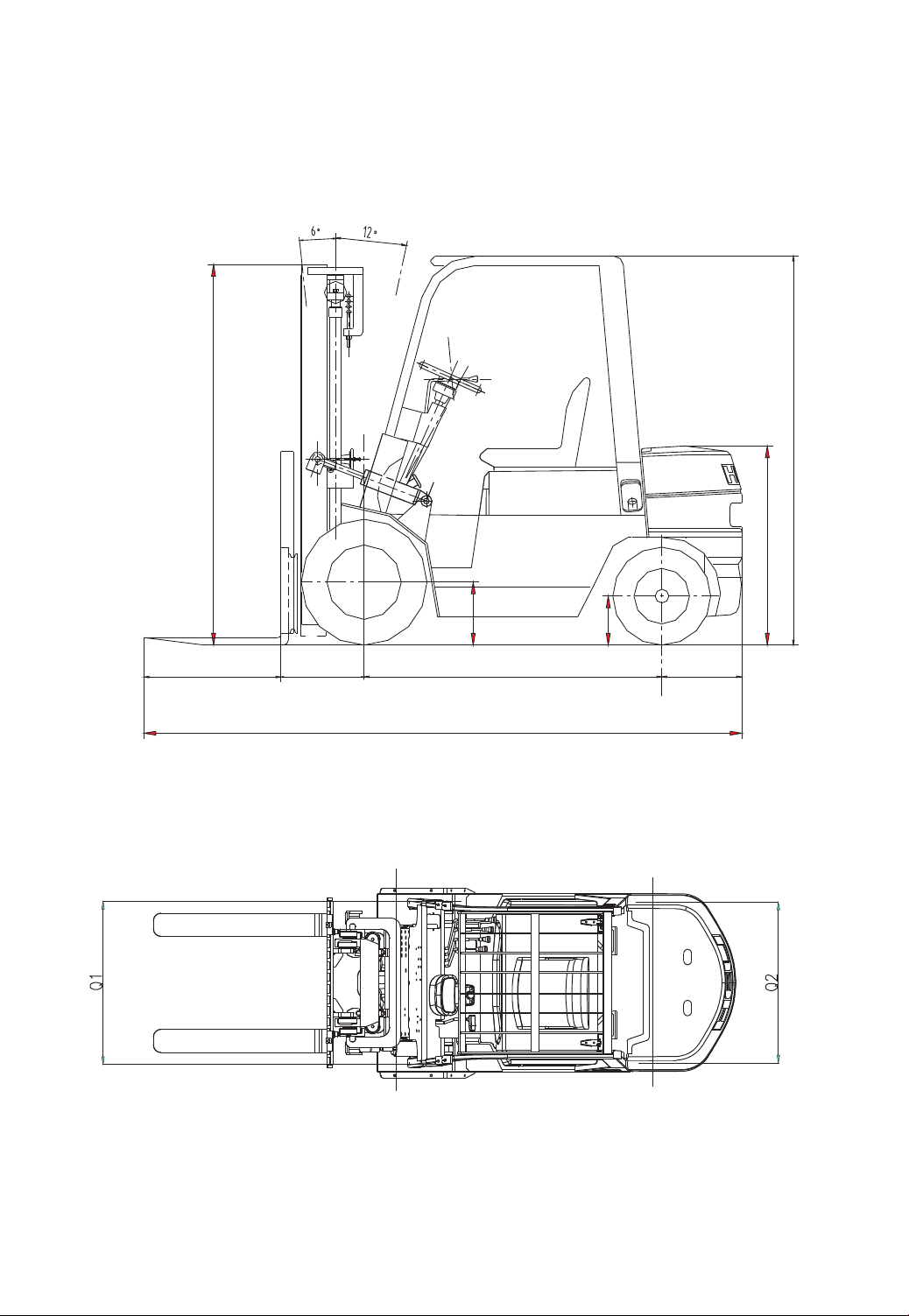
II.Specifications of Forklift Trucks (See Table 1)
External View of Forklift Trucks
-7-
L
L1 B F C
D
1040(1150)
245(275)
320(345)
2100(3.8t 2195)

Specifications of Forklift Trucks
Table 1
kg
mm
mm
mm
Fwd/Rwd
mm
mm
2000
500
3000
155
6°/12°
580
550
2170
1920
2500
2230
1940
3000
160
470
450
3500 3800
170 150
370 400
340 360
2420 2590
2110 2415
CPC 20
CPCD 20
CPC 25
CPCD 25
CPC 30
CPCD 30
CPC 35
CPC 38
CPCD 35
CPCD 38
20
19
20
19
8.3
12.1
20
21
20
19
20
19
8.3
14.7
20
27
20
19
20
19
8.9
12.1
18
18
20
19
20
19
8.9
14.7
18
23
20
19
20
19
9.8
11.3
20
15
20
19
20
19
9.8
14
20
18
20
19
20
19
10
11.3
20
15
20
19
20
19
10
14
20
16.5
20
19
20
19
11.7
15
20
15
20
19
20
19
11
20
20
20
Model
Parameters
Rated Capacity
Load Center
Standard Lift Height
Free Lift Height
Mast Tilt Angle
Lifting Speed
mm/s
Travel Speed
km/h
Mechanical
Hydraulic
Max. Drawbar
Force
kN
Gradeability
%
Min. Turning Radius
Min. Intersecting Aisle
Unloaded
Loaded
Unloaded
Loaded
Unloaded
Loaded
Unloaded
Loaded
Unloaded
Loaded
Performance
-8-

mm
mm
mm
mm
mm
mm
mm
mm
mm
mm
mm
mm
mm
mm
kg
CPC 20
CPCD 20
CPC 25
CPCD 25
CPC 30
CPCD 30
CPC 35
CPC 38
CPCD 35
CPCD 38
Specifications of Forklift Trucks
Table 1
Model
Parameters
Overall Length L
Overall Width
Overall Height D
Overall Height(extended mast)
Wheelbase F
Tread
Front Overhang B
Rear Overhang C
Forks
Fork Spacing (adjustable)
Underclearance (at mast)
Service Weight (with water & oil)
Dimensions
Front Q1
Rear Q2
Length L1
Width
Thickness
3646
1150
2070
4030
1600
970
970
482
494
1070
100
45
245~1020
110
3680
3752
1225
2090
4250
1700
1000
970
487
495
1070
125
45
250~1090
135
4270
3763
1225
2090
4250
1700
1000
970
498
495
1070
125
50
250~1090
135
4700
3962
1225
2090
4265
1900
1000
970
497
495
1070
150
50
300~1080
135
4850
3422
1150
2070
4030
1600
970
970
482
420
920
100
45
245~1020
110
3320
-9-

III.Description of Main Parts of Forklift Truck
Power System — Transmission System —
Clutch — Mechanical Transmission
Torque Converter — Hydraulic Transmission
Reduction Gear & Differential — Drive Axle — Steering System — Steering Axle —
Lifting System —
Operation of Brake and Clutch Pedals (Clutch type truck)
Operation of Brake and Inching Pedals
(Torque converter type truck)
Parking Brake
Operation of Accelerator
Operation of Choke
— Hydraulic System — Electric System
Operating System —
-10-

IV.Construction, Principle, Adjustment and Maintenance of
Forklift Trucks
We herein explain the construction, basic principle, adjustment, disassembly and
assembly, repair, troubleshooting and other contents of forklift trucks made by us for
the operators to use, maintain and repair them more successfully.
1. Power System
1.1 General Description
The power of K series forklift trucks with 2 to 3.5 ton capacity is provided by
diesel engine Xinchang A490BPG-76, Xinchang C490BPG-200 or Quanchai
QC490GP. DachaiCA498-97,and 3.8 ton capacity is provided by diesel engine
Xinchang A4965BPG, Quanchai QC495G or Dachai CA498-97.Refer to relevant
manual for the details of operation and maintenances for the engine.
1.2 Fuel System
The fuel system is composed of a tank, fuel volume sensor and fuel meter (see
Fig. 1-1).
Fig. 1-1 Fuel tank for 2-3.8 ton forklift trucks
Fuel volume sensor
Highest lever 52L
Lowest lever 52L
To the oil inlet end of the fuel
injection pump of the diesel engine To the oil return end of the diesel engine
-11-

1.2.1 Fuel tank
The fuel tank is a welded construction integrated with the truck frame. It is
located on the left side of the truck frame and has a capacity of 52l for 2-3.8 ton
trucks. The fuel volume sensor is installed on the tank cover to detect the fuel level.
1.2.2 Fuel volume sensor
Fig. 1-2 Fuel volume sensor
The sensor is designed to convert the remaining amount of fuel into voltage. (See
Fig.1-2) The sliding type resistor made of alloy steel wire is linked with float. As the
float moves up and down, resistance is changed. With electro-magnetic fuel meter, the
remaining amount of fuel in the fuel tank can be read off the meter panel.
1.2.3 Maintenance
Once every 100 working hours, it is required to maintain the fuel system
according to the following methods. Once every 600 working hours, it is required to
clean the fuel tank.
The highest lever
Float
The lowest lever
Truck capacity
Float position
1
1/2
0
2-3.8 (ton)
Resistance (Ω)
55
43
10
-12-
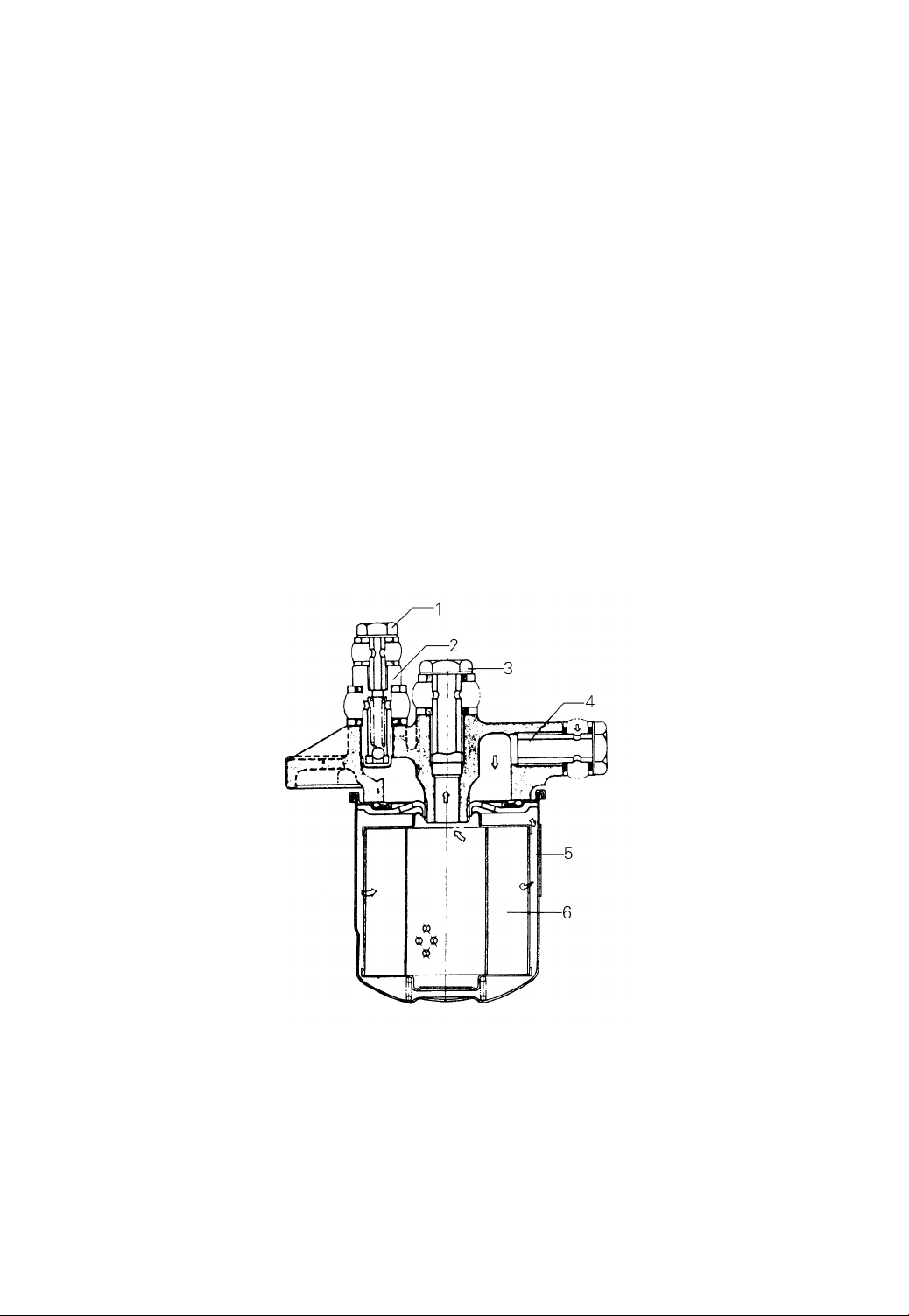
(1) Fuel filter
The fuel filter is for clearing the fuel of the dust and impurity. It is installed
between the feed pump and injection pump.
The filter is of cartridge type. Generally it can not be disassembled. Replace the
filter assembly when required.
For maintenance of the filter, proceedings are as follows (See Fig.1-3):
a) Once a 100 working hours, it is required to remove the cartridge cover by
specific tools and then take out the filter element.
b) Once a 600 hours operation, it is required to replace the filter assembly.
c) After the re-fitment of filter, check it for leaks.
d) Check overflow valve (1) for correct working.
Fig. 1-3 Fuel filter
(2) Cleaning of fuel tank
Once every 600 working hours, the fuel tank should be cleared.
-13-

2.Clutch and Clutch Pedal
Table 2
2.1 General Description
The clutch consists primarily of pressure plate, friction piece and clutch yoke.
The pressure plate is bolted to the engine flywheel. There is an inspection hole
attached to the clutch cover. The clutch pedal pushes the clutch yoke by push rod in
order to release the friction piece from flywheel which normally mesh together.
2.2 Replacement of Friction Piece
(1) Press the clutch pedal and place three spacers between the pressure plate case
and release lever to cause the friction piece apart.
(2) Turn counter clockwise the slide lead screw in the upper of the transmission
to let the driving shaft go into the transmission (See Fig.3-1).
(3) Remove six mounting bolts on the pressure plate case to cause the flywheel
apart and remove the old friction piece right away.
(4) When a new friction piece is installed, notice the hub (See part 5 in Fig.2-1)
with the longer spline boss being toward the transmission.
(5) Turn the slide lead screw clockwise and pull out the driving shaft step by step
and let its spline match with the hub spline.
CPC20、25、30、35、38
Single plate, dry
275
175
8.0
352
about 10
Foot operated
Truck Model
Parameters
Type
Dimensions
of Friction
Piece
mm
Outer dia.
Inner dia.
Thickness when pressed
2
Friction Surface Area cm
Weight kg
Operation Mode
-14-
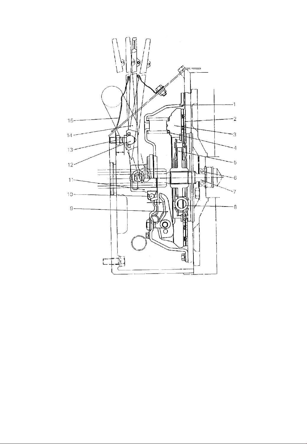
(1) Pressure plate case (2) Friction piece (3) Pressure plate (4) Pressure spring
(5) Hub (6) Bearing (7) Driving shaft (8) Coil spring (9) Release lever
(10) Release bearing (11) Release bearing block (12) Bolt (13) Lock nut
(14) Release yoke (15) Cover
Fig.2-1 Clutch
(6) After making certain that the driving shaft end has entered the middle
bearing of the flywheel, tighten the slide lead screw to the torque of 107-119N.m
(10.9-12.1kgm).
(7) Install the pressure plate case on the flywheel.
-15-
(8) Press the clutch pedal and remove the three spacers.
(9) Adjust the travel of the clutch pedal. (See Fig.2-2)
2.3 Clutch Pedal
The clutch pedal and the brake pedal are fitted on the same bracket. The clutch
pedal is secured on the transmission.
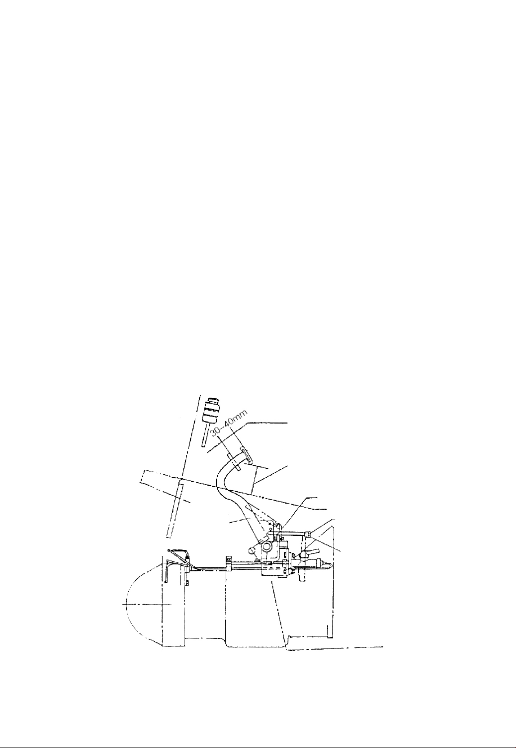
2.4 Adjustment of Clutch Pedal Travel (See Fig.2-2)
(1) Loosen clutch pedal stopper bolt (a).
(2) Using stopper bolt (a) to get a pedal height from the floor of 111mm. Spare
travel is 30-40mm.
(3) Detach the spring at the end of the clutch pedal and loosen the nut (b).
(4) Press the clutch pedal about 30 to 40mm. At this time, pull the release yoke
forward. When resistance is felt, turn spherical nut (b) until it comes into contact with
release yoke and then lock with lock nut (c).
(5) Install the pedal spring properly.
Spare travel
Pedal height 115mm
Stopper bolt (a)
Spherical bolt (b)
Lock nut(c)
Clutch pedal
Fig.2-2 Clutch pedal
-16-

3.Transmission, Reduction Gear and Differential
3.1General Description
The drive unit of clutch type truck is a one-body construction consisting of the
transmission, reduction gear and differential (Fig.3-1). The transmission is provided
with a synchromesh mechanism that synchronizes the rotation of gears which are
about to be meshed, ensuring smooth gear shifting. The transmission of this type
avoids clashing gears and reduces noise arising when shifting, especially shifting from
forward to reverse or vice versa.
3.2 Transmission
The transmission consists mainly of a driving shaft, an output shaft, a main shaft
and an idler shaft, each having gear(s) of different sizes on it. The gear(s) can be
shifted with the aid of the synchromesh mechanism installed on the main shaft by
operation of the shift handle. The power from the output shaft is transmitted through
the reduction gear differential and half shafts to the drive shaft.
3.2.1 Driving shaft and slide lead screw
Transmission
Type
Gears number
Gear ratio FWD 1st/2nd
BWD 1st/2nd
Reduction gear
Gear
Reduction ratio
Differential
Gear
Reduction ratio
Differential gear
Oil amount
Dry weight (no oil)
Manual-shift, slide type synchromesh mechanism
FWD:2 BWD:2
3.253/1.407
3.204/1.386
Spiral bevel gear
2.1
Spur gear
6.182
Bevel gear
8 L
Approx.100kg
-17-

Driving shaft’s end toward the clutch is held by the ball bearing located in
flywheel, another end fitted with input gear is held in transmission case by the ball
bearing and its middle portion is held in the bearing retainer which is fixed in
transmission case with the slide lead screw. When the replacement of the friction piece
is required, the driving shaft along with the bearing retainer is moved axially through
turning the slide lead screw until the shaft end toward the clutch returns inside the
transmission case.
3.2.2 Output shaft
The cluster gear is installed on the output shaft through two needle bearings and
a spacer. Also the output gear is splined to the output shaft through a spacer. The
output shaft is held in the transmission case with two tapered roller bearings and
several shims are used to adjust the backlash between the output gear and the bearing.
The bigger gear of the cluster gear normally meshes with the input gear and high
speed gear while the smaller gear with the low speed gear. The output gear normally
meshes with the forward gear or reverse idler gear.
3.2.3 Main shaft
The high and low speed reverse and forward gears are all installed on the main
shaft through needle bearings. As they normally mesh with the cluster gear, idler gear
and input gear respectively, it’s easy to shift for changing speed or direction
synchronizer by operating the synchromesh mechanism.
3.2.4 Idler shaft
Both ends of the idler shaft are supported by the transmission case and its rear
end is positioned by a steel ball. The idler gear is installed on the idler shaft through
needle bearings and normally meshes with the reverse gear and output gear.
3.2.5 Rotating rod and shift forks (See Fig.3-1 and Fig.3-2)
Two rotating rods are used for performing the changeover in travel speed and
direction respectively. The shift forks are supported on the shift rods. The ball is
designed to rest in the notch of the shift rod to secure gearshifting position.
-18-
This manual suits for next models
9
Table of contents
Other HELI Forklift manuals


