Table of Contents
1.
Maintain list ..................................................................................................................................1
a.
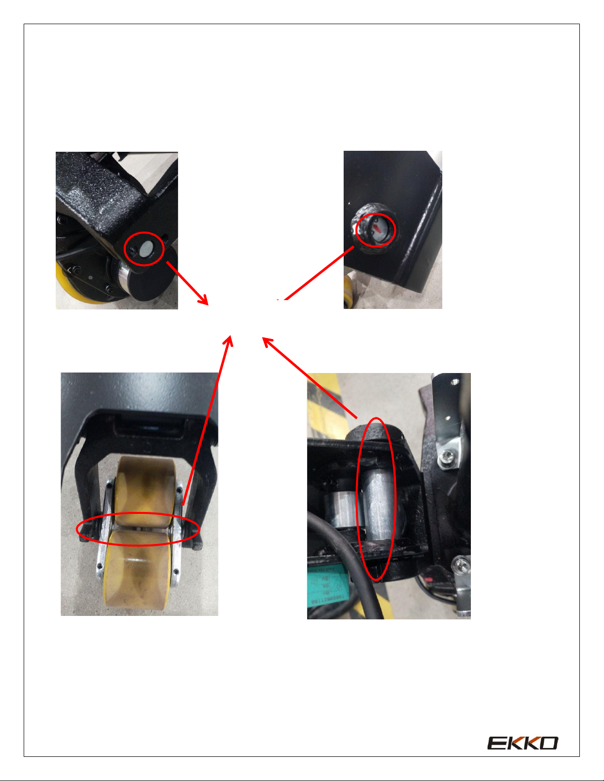
Main part overview....................................................................................................................1
b.
Lubrication
points......................................................................................................................3
c.
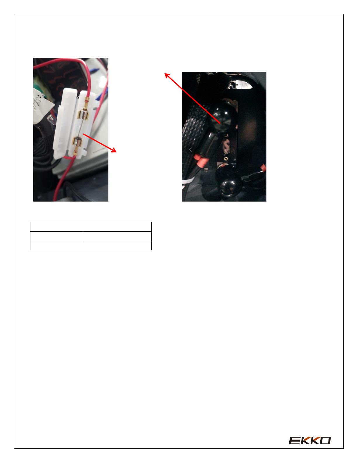
Check and refill hydraulic
oil
.....................................................................................................4
d.
Check electrical fuses ................................................................................................................5
2.
Failure
analysis..............................................................................................................................6
a.
Common
failure
analysis
............................................................................................................6
b.
Controller fault code
display
......................................................................................................7
c.
Troubleshooting for common faults...........................................................................................9
3.
Wiring/circuit
diagram................................................................................................................14
a.
Circuit diagram........................................................................................................................14
b.
Hydraulic
circuit......................................................................................................................16
4.
Disassembly of main parts...........................................................................................................17
a.
Electromagnetic
brake
adjustment
............................................................................................17
b
Disassembly
of
driving
assembly
.............................................................................................17
c.
Disassembly
of
Electromagnetic
brake
.....................................................................................18
d.
Drive
internal
gear,
Bearing
......................................................................................................
18
e.
Operating
handle
assembly
.......................................................................................................19
5.
CURTIS Hand
programmer
..........................................................................................................19