Heliodyne GOBI 406 001 User manual

EXCELLENCE
BY DESIGN
INSTALLATION
GUIDE
HPAK SYSTEMS
SOLAR HOT WATER

TABLE OF CONTENTS
1. PREPARATIONS 3-9
GOBI INSTALLATION
10-11
2.
12-13
14-16
20
21
17-19
3. HPAK INSTALLATION
4. PIPING
5. COMMISSIONING
6. O & M

NOTES 3
SOLAR HOT WATER
1. PREPARATIONS
1.0. General Notes
1.0.0. Safety Guidelines
Carefully review all instructions in this manual for installation and use. Do not modify Gobi
Collectors or Helio-Pak under any circumstances; use only as designed. This manual and
its content are integral parts of both the Helio-Pak and Gobi Solar Collector warranties.
Noncompliance with these guidelines will void all warranties.
Follow all local building codes and regulations, as well as these industry accepted
guidelines and standards:
IAPMO USEC, UBC, UPC
ASHRAE Solar Energy Equipment
NFPA 70 National Electric Code
ASCE 7-05 Minimum Design Loads for Buildings and Other Structures
Select an installation location that is easily accessible for maintenance and servicing.
1.0.1. Collector Storage and Handling
Keep collectors covered when storing.
Avoid lifting collectors by the headers. Take care not to scratch the tempered solar glass;
follow the glass breakage guidelines at the end of this manual in case of breakage.
Gobi collectors nest and lock into each other for horizontal transportation. Do not
transport Gobi upside down or standing on a side.
1.0.2. Collector Installation
Make a site visit prior to installation to verify adequate installation conditions:
Collector sun exposure, especially during crucial solar hours of 10AM• – 2PM.
Take into consideration deciduous tree shading, structures, chimneys, etc.
Use a minimum tilt of 10• ° in mild areas and 30° in areas with snow.
Orient collectors within 20° of true South (in North latitudes); use internet maps•
rather than compass readings for verification.
Ideal collector tilt for hot water production is equal to site latitude. For space•
heating combination systems, use tilt equal to latitude plus 15°. Heliodyne
recommends a standard of 35° for hot water and 45° for space heating,
regardless of location. Use racks only when necessary, as variation up to 15°
can have only small effects on performance.
Avoid banking• of snow and ice below or on the collectors.
Never mount Gobi collectors horizontally in a drainback system.•
• Heliodyne recommends 6-12” of flex tubing before any rigid copper lines to allow
for thermal expansion in the copper tubing.
1.0.3. Minimum Heat Storage
A minimum of 1.5 – 2.0 gallons of liquid heat storage per square foot of Gobi collector
(e.g., 60 – 80 gallons per Gobi 410) is recommended.
Minimize stagnation (no load, no flow) conditions on peak output days by using
appropriate system sizing and maximizing year round usage. For design assistance,
contact Heliodyne.
Ensure the backup heating capacity is properly sized to produce hot water for installation
site on days of little or no solar energy production. Use only ASHRAE 90.2 compliant
storage tanks and heaters with R-16 or higher.
1.0.4. Equipment for Installation
For a complete and functional SHW system, ensure the following equipment is ready for
installation at the job site:
Gobi Solar Collectors•
Rack or Flush mount hardware kit•
Appropriate roof penetration hardware and sealant•
Copper tubing, type M or L for collector / heat transfer appliance connections,•
adapters, elbows and fittings.
96/4 Tin/Silver solder•
Non-rubber based insulation (Armaflex); 1/2” wall / R2.6l minimum•
UV resistant covering or coating for outdoor exposed insulation•
Helio-Pak heat transfer appliance (HPAK)•
Isolation valves, tempering valve, air vent•
Storage tank with adequate volume for collectors installed•
Connections for storage tank (flexible or otherwise)•
Dyn-O-Flo HD high temperature propylene glycol or equal•
Pipe hangers or supports installed per code requirement installed without•
compromising any insulation.
1.0.5. Tools
Heliodyne collectors and heat transfer appliances do not require any special tools. Never
use plumbing wrenches on hex connections. Always tighten the bolts rather than the
nuts. Aside from using the standard plumbing tools (torch, pipe cutter, etc.) the following
tools and sizes are used in Heliodyne equipment:
9/16” wrench / socket for 3/8”- 16 bolts and nuts•
3/4” wrench / socket for 1/2” - 13 hanger bolts and nuts•
Adjustable hex wrench for 1.25” thru 1.875” hex sizes•
Phillips screw driver (for tank sensor installation)•
1/4” drill bit for 3/8” lag screws•
3/8” drill bit for 1/2” lag screws•
1.0.6. Safety Equipment
Working on roof tops and other elevated collector installation sites as well as using
flames can be dangerous; use extreme caution and follow all local codes and good safety
practices when installing. Heliodyne is not responsible for job safety nor any accidents
that may occur, and always recommends:
Safety glasses•
Roof harness•
Scaffolding rather than ladders•
Solder in well ventilated areas
•
1.0.7. Heliodyne OG-300 Certified Systems and SRCC Numbers
Installers: check box next to OG-300 system installed (if applicable)
HPAK 016 1 408 G 65 ACS 300-1992-010A
HPAK 016 1 410 G 80 ACS 300-1992-010B
HPAK 016 2 408 G 120 ACS 300-1992-010C
HPAK 016 1 406 G 50 ACS 300-1992-010J
HPAK 016 1 406 G 80 ACS 300-1992-010K
HPAK 016 2 406 G 80 ACS 300-1992-010L
HPAK 016 2 406 G 120 ACS 300-1992-010M
HPAK 016 1 408 G 80 ACS 300-1992-010N
HPAK 016 2 410 G 120 ACS 300-1992-010O
HPAK 016 1 410 G 65 ACD 300-1992-013A
HPAK 016 2 408 G 80 ACD 300-1992-013B
HPAK 016 2 408 G 120 ACD 300-1992-013C
HPAK 016 2 410 G 120 ACD 300-1992-013D
HPAK 016 1 408 G 65 ACD 300-1992-013F
HPAK 016 1 406 G 80 ACD 300-1992-013G
HPAK 016 2 406 G 80 ACD 300-1992-013H
HPAK 016 1 408 G 80 ACD 300-1992-013I
HPAK 016 1 410 G 80 ACD 300-1992-013J
HPAK 016 1 410 G 80 ACD Z 300-1998-001A
HPAK 016 2 408 G 80 ACD Z 300-1998-001B
HPAK 016 2 408 G 120 ACD Z 300-1998-001C
HPAK 016 2 410 G 120 ACD Z 300-1998-001D
HPAK 016 1 408 G 65 ACD Z 300-1998-001F
HPAK 016 1 406 G 80 ACD Z 300-1998-001G
HPAK 016 2 406 G 80 ACD Z 300-1998-001H
HPAK 016 1 408 G 80 ACD Z 300-1998-001I
The solar energy system described in this Manual, when properly installed
and maintained, meets or exceeds the minimum standards established by
the SRCC. This certification does not imply endorsement or warranty of this
product by SRCC.
Contact Heliodyne for service in your area: 1.888.878.8750
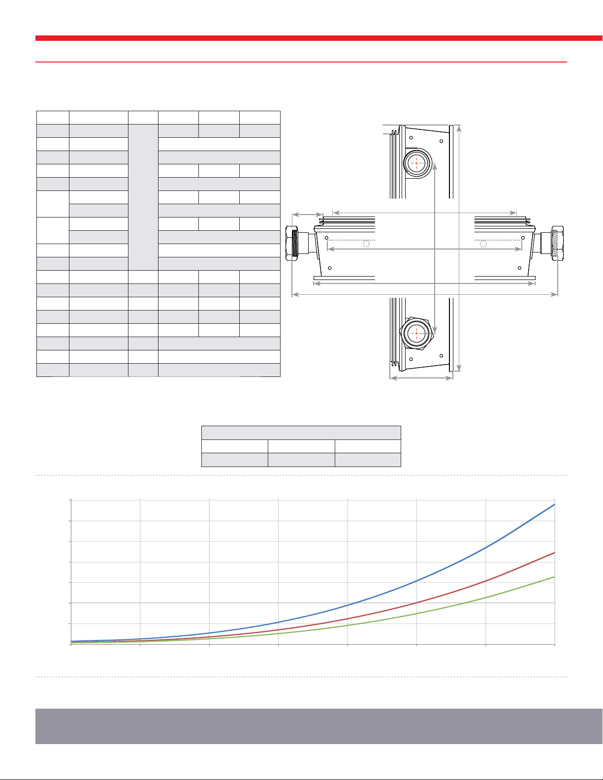
COLLECTOR SPECIFICATIONS
1.1. Technical Specifications for Gobi
DIM DESCRIPTION UNITS GOBI 406 GOBI 408 GOBI 410
L Length
inch
81.56 97.56 121.56
W Width 47.56
T Thickness 3.90
H Header Length 76.88 92.88 116.88
M Header Width 50.25
A
Aperture Length 79.25 95.25 119.25
Aperture Width 45.25
P
Plate Length 78.0 94.0 118.0
Plate Width 46.25
D Flashing Base 0.61
F Flashing Header 1.93
L x W Gross Area ft226.94 32.22 40.15
ALx AWNet Area ft224.90 29.93 37.47
g Dry Weight lb. 97 110 128
G Full Weight lb. 103.2 116.9 135.8
V Volume Gal. 0.75 0.83 0.95
- Max Pressure PSI 150 (10 Bar)
- Test Pressure PSI 300 (20 Bar)
- Stag. Temp. °F 397.6 (203 °C)
A
F
D
P
W
M
T
LH
1.2. Flow and Pressure Loss1
RECOMMENDED DESIGN FLOW RATES WITH GLYCOL2
GOBI 406 GOBI 408 GOBI 410
0.85 Gal / min 1.0 Gal / min 1.25 Gal / min
PRESSURE DROP PLOT
1. Losses calculated at recommended Gobi design flow rates for 50/50 propylene glycol / water solution.
2. Minimum flow rates shown. Do not exceed recommended flow rates by more than (3) times.
Number of Gobi in Array (8 Max)
ΔP (Inches H20)
1
0
10
20
30
40
50
60
70
2345678
Gobi 410
Gobi 408
Gobi 406

COLLECTOR ORIENTATION AND PLUMBING 5
SOLAR HOT WATER
1.3. Gobi Orientation and Plumbing
OR
OR
Figure 1.3.-2 Two DOS-Discs Per Vertical ArrayFigure 1.3.-1 DOS-Disc Assembly (p/n: 50013) Figure 1.3.-3 Two DOS-Discs Per Horizontal Collector
S
15° 15°
+ / - 15°
Helio-Pak
Helio-Flo
Drain Back
Helio-Pak
Helio-Flo
Drain Back
Combi DHW:
DHW / Pool:
45°
35°
2x
66
67
47 *001 Models Only
*032 Shown
*Optional
2
14
3
16 13
5
717
11 12
25 26
1
24
5
8
45
4
61
62
63
65
64
15 13
9
20 21
13
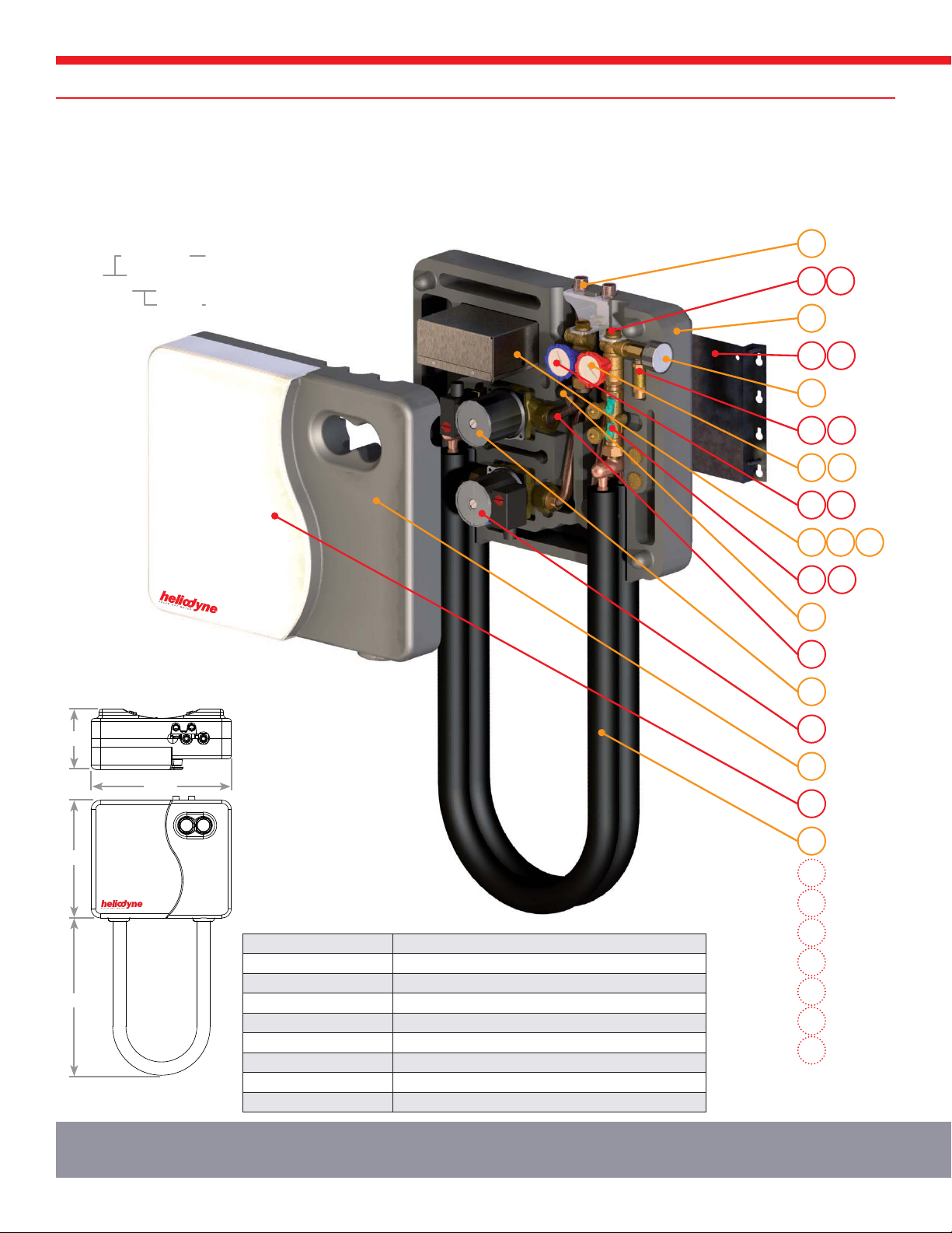
HPAK SPECIFICATIONS
1.4. Helio-Pak Heat Transfer Appliance HPAK
Insulated solar hot water system, closed loop glycol / water, double wall heat exchanger with visual leak detection, control and sensors, filling
valve and hot / cold temperature and pressure indication.
*HPAK 032 shown.
024 & 048 HX’s measure 43”
25.0”*
18.9”
9.7”
22.5”
Figure 1B-1: HPAK Dimensions
HPAK 0XX 00X
Heat Exch.
000 Std
001 Pro
016 ,000 Btu/hr
024 ,000 Btu/hr
032 ,000 Btu/hr
048 ,000 Btu/hr
Control
1.5. Technical Specifications
Maximum Operating Conditions 150 psig / 275 °F
Heat Transfer Fluid 40-50% Dyn-O-Flo HD and Water
Solar Loop Connections Compression fittings for 3/4” Type M or L Copper, 7/8” OD (ASTM B88)
Domestic Water Connections 3/4” Male NPT Fittings
Pressure Relief Barbed Hose Connection (For 1/4” ID Hose)
Gaskets EPDM
Domestic Water Contact Material Type M or L Copper & Bronze (Pump)
Insulation EPP Foam (Casing), Armaflex (HX)
Thermal Conductivity 0.25 Btu·in / hr·ft2·°F (0.036 W/m·K)
Item
Numbers

HPAK SPARE PARTS LIST 7
SOLAR HOT WATER
1.6. HPAK Replacement Parts
1.6.0. HPAK Spare Parts Table
ITEM CODE PART NUMBER DESCRIPTION QUANTITY
1
HPAK 16 DW
HPAK 24 DW
HPAK 32 DW
HPAK 48 DW
40020
40095
40096
40097
Pre insulated double wall HPAK U Tube
Heat Exchanger with visual leak detection (IAPMO Listed) 1
2 EPP Foam Front 21250 Front insulation casing 1
3 EPP Foam Back 21251 Back insulation casing 1
4 Acrylic Cover 21254 Front white acrylic cover with logo 1
5a UPS 15-58 Cil2 23098 PPG Volute 3-Speed circulation pump (HPAK 016 Models) 2
5b UPS 15-78 Cil2 23299 PPG Volute 3-Speed circulation pump (HPAK 024-048 Models) 2
7 PRV 23001 150 psig, 1/4” NPT pressure only relief vavle 1
8 PGauge 21214 Back entry pressure gauge, 0–160 psi 1
9 2-40FloCast 21199
21202
Bronze flow casting, with flow meter input, Pro models only
Bronze flow casting, without flow meter input 1
11 Comp. Nut 21191 7/8” OD copper tube brass compression nut 2
12 Comp. Ring 21192 7/8” OD copper tube brass compression ring 2
13 Combo Gasket 21186 EPDM gasket for combo valves 3
14 Combo Valve: Hot 23090 Hot combination valve: check, ball, temperature 1
15 Combo Valve: Cold 23091 Cold combination valve: check, ball, temperature 1
16 Combo Valve: Fill 23092 Filling combination valve 1
17 EX-2
EX-5
23030
23031
2-gallon bladder type expansion tank
5-gallon bladder type expansion tank 1
20 Tank Bracket 21204 Tank mounting bracket 1
22 Mtg Screws 21194 1/4 - 20 x 1” Self-tapping screws for tank mount 8
24 HP Elec. Box - bot 21198 HPAK electrical box - bottom 1
25 HP Elec. Box - top 21197 HPAK electrical box - top 1
26 Delta- T 21153
21270
Delta - T Control Board
Delta - T Pro Control Board, Pro models only 1
29 SENS 000 001 23029 10,000 Ohm Thermistor Sensors 2
45 HPAK - DHW Tube 40029 DHW pump inlet tube, flanged, 3/4” Type M 1
47 Grundfos VFS 2-40 23086 Grundfos vortex flow and temperature sensor, Pro models only 1
Optional Equipment (Not Included in HPAK Package)
61 ZZZZ 000 003 23020 Tempering valve, 3/4” sweat 1
62 AV700 23021 Air vent for filling, 1/2” Male NPT 1
63 SENS 000 002 23025 Sensor wire -
64 DFLO 001 000 23040 Dyn-O-Flo HD propylene glycol concentrate -
65 ZZZZ 000 005 23023 Tank bypass valve 1
66 ITLS 000 002 50064 Collector loop filling station -
67 ITLS 000 001 50078 Propylene glycol test kit -
HPAK SYSTEM COMPONENTS OVERVIEW
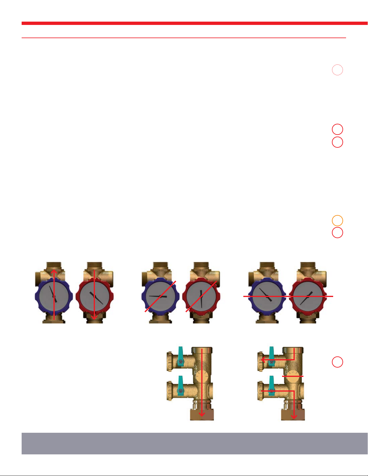
1.6.3. Operation of Combo Valves
The combo valves are integrated check and ball valves, with temperature gauges. Cracking pressure (minimum fluid flow pressure)
of the check valves is 0.30 psi. The valves can be operated by turning the plastic handles clockwise, with note taken of the position
of the slots on the handles, indicating valve position as pictured in figures 1.6.3.-1 – 3 below. To ensure proper compression fitting
seals, clean and round copper tubing must be used. Use a counter wrench on the hex provided to fully torque compression nut
fittings. Bush up or down as necessary for proper flow rates.
1.6.1. Tempering Valve
Install a tempering valve to prevent scalding; the solar storage may reach 180°F. Some areas may require a rated Anti-Scald
valve.
For dual tank systems with a gas backup, install the tempering valve before the gas water heater and after installing the solar
storage tank, to avoid a service call for high limit fuse replacement. For dual tank systems with an electric tank, the tempering
valve may be installed before or after the tank. For instantaneous water heaters as backup, consult the manufacturer for the
recommended method of tempering or bypass of solar heated water into the heater.
1.6.2. System Overheat Protection and Operation of Pressure Relief Valve and Expansion Tank
The HPAK comes with a preinstalled pressure only relief valve, nonadjustable and pre-set at 150 psig. A 1/4“ barbed hose fitting is
supplied for routing relief fluid to a drain or retaining vessel.
In addition, the system comes with a pre-sized bladder type expansion tank. The acceptance volume of the expansion tank
should be large enough to store up to 17 – 20% of the total collector system fluid volume.
With these safety precautions, and high temperature Dyn-O-Flo HD propylene glycol, the system can stagnate for short periods.
If extended periods (2 weeks or more) are expected, install a Delta-T Pro with the proper vacation setting. Additionally, the
system should never have less than 1.5 gallons of storage for each square foot of collector surface area.
1.6.4. Operation of Filling Valve
The filling valve integrates three gate valves into one.
The green handles operate the inlet and outlet of the
valve, while the drain fitting on the side enables either
filling or system operation. Always fill the system in the
direction of the flow path.
If not using a Heliodyne filling station, hose adapters
are set into the HPAK foam to the right of the fill
valve.
16
14
15
61
7
17
Figure 1.6.4.-1: Drain Fitting Open
(Operation Position)
Figure 1.6.4.-2: Drain Fitting Closed
(Fluid Servicing)
Figure 1.6.3.-1: Ball Valves Open
(Operation Position)
Figure 1.6.3.-2: Check Valves Open
(Fluid Servicing)
Figure 1.6.3.-3: Ball Valves Closed
(HPAK Servicing)
Item
Numbers

HPAK SYSTEM COMPONENTS OVERVIEW 9
SOLAR HOT WATER
1.6.7. 3-Speed Pump Operation
The DHW and collector circulation pumps are identical bronze volute pumps; they come prewired, set at speed 2. Depending on
Gobi surface area installed, the speed may need to be adjusted by rotating the red knob to desired speed. Use Table 1.6.7.-1 for
pipe size, collector surface and speed reference. Table 1.6.7.-2 shows the pump performance.
UPS 15-58 Cil2 Power Ratings:
Speed 1: 55 Watts
Speed 2: 65 Watts
Speed 3: 75 Watts
1.6.5. Solar Control and HPAK electrical
THE ELECTRICAL INSTALLATION SHOULD BE PERFORMED BY AN AUTHORIZED PROFESSIONAL. FOLLOW ALL LOCAL REGULATIONS AND
CODES WHEN INSTALLING WIRE, FUSES, GROUNDING, ETC. PROTECT THE HPAK FROM OVERCURRENT. BEFORE ANY ELECTRICAL WORK
IS DONE, ENSURE THE HPAK LINE CORD IS DISCONNECTED FROM THE ELECTRICAL SOURCE.
Both the HPAK 000 and 001 come with the basic internal electrical wiring already completed. For simple DHW operation, the
installer only needs to plug in the HPAK line cord into a nearby 120 VAC, 60 Hz grounded wall outlet and wire the storage and
collector sensor appropriately. The control comes prewired with two sensor lines. Use 22 AWG or larger cable if the sensor lines
need to be extended. Connect the sensors to wire using non-metal wirenuts, or other corrosion resistant connection method. Ensure
the control high limit is set at or below the tank manufacturer’s recommended limit.
If attaching additional sensors or wiring, such as for the Pro models, remove the top cover for the electrical box and make the
appropriate connections. See the Delta-T or Delta-T Pro manual for controller installation.
1.6.6. Flow Sensor: 001 Models
The HPAK pro models come with a digital vortex flow and temperature sensor preinstalled and wired to the Delta-T pro control. No
adjustment is necessary. See the Delta-T Pro Manual for in-depth explanation.
25
26
24
5
5
47
Table 1.6.7.-1: HPAK Piping Recommendations
HPAK HEAT EXCHANGER 016 024 032 048
Recommended Flow Rate (GPM) 3 4 6 9
Max Gobi Surface Area (Ft2) 96 144 192 288
Recommended Pump Speed 1 2 2 3
Max Piping Resistance (Ft H20)2567
Item
Numbers
Figure 1.6.7.-1: Grundfos UPS 15-58 CiL2 Pump
16
18
6
8
10
12
14
0
2
4
02468101214
40
50
60
70
80
40
02468101214
Table 1.6.7.-2: UPS 15-58 CiL2 Performance
Q [US GPM]
SPEED
H [ft]P [W]
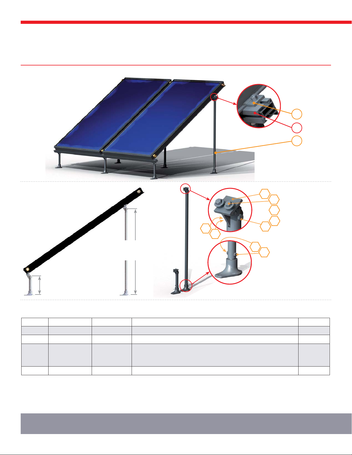
2. MOUNTING HARDWARE
2
1
3*002 Shown
RACK 000 000: 4.00”
RACK 000 001: 6.40”
RACK 000 002: 10.70”
2.0.0. RACK 000 00X Components and Leg Assembly
2.0. Rack Mounting Overview
B
A
C
D
D
C
E
3/8-16 x 1” SS Bolt
With Flat Washer
Lock Washer
3/8-16 SS Nut
3/8-16 x 1-3/4 SS Bolt
001 & 002:
3/8-16 x 1-3/4 SS Bolt
000:
3/8-16 x 2 SS Bolt
3/8-16 SS Serrated Flange Nut
Rail T - Foot
F
E
RACK 000 000: 47.30”
RACK 000 001: 49.40”
RACK 000 002: 49.40
2.0.1. RACK Replacement Parts
ITEM CODE PART NUMBER DESCRIPTION QUANTITY
1 CLIP 000 000 40082 Gobi Rail Clamp, 3/8-16 x 1” SS Bolt, Flange Nut (set of 4) 1 / Gobi
2 RAIL 002 000 40090 2x102.0” Gobi Mounting Rail, 2xCLIP 000 000 set See Note 1
3
RACK 000 000
RACK 000 001
RACK 000 002
40080
40081
40083
Commercial Mount, 4” Front Leg, 47” Rear Leg
Flat Roof Rack Mount, 4” Front Leg, 47” Rear Leg
Flat Roof Rack Mount, 8” Front Leg, 47” Rear Leg
# Gobi + 1
4 RAIL 000 001 40089 Splice Kit for Joining Rails (Includes 2 for upper and 2 for lower rail) 1 Kit
1. Order minimum quantity of rails that will accommodate number of collectors in array.
2. RACK 000 00X Kits require field assembly.
3. 47” Rear tilt leg is not for tilts greater than 45° on 408 or 410 collectors
RACK MOUNTING INSTALLATION
45-50.25” MAX
2 X
3/8 x 3-1/2” Lag*
OATEY®
1-1/4” – 1-1/2” DIA
Shingle
(Cutout not required)
Gobi Tilt = 45°
Gobi Tilt = 35°
RACK 000 000: 43.0”
RACK 000 001: 43.3”
RACK 000 002: 38.7”
RACK 000 000: 61.8”
RACK 000 001: 61.4”
RACK 000 002: 55.3”
OR
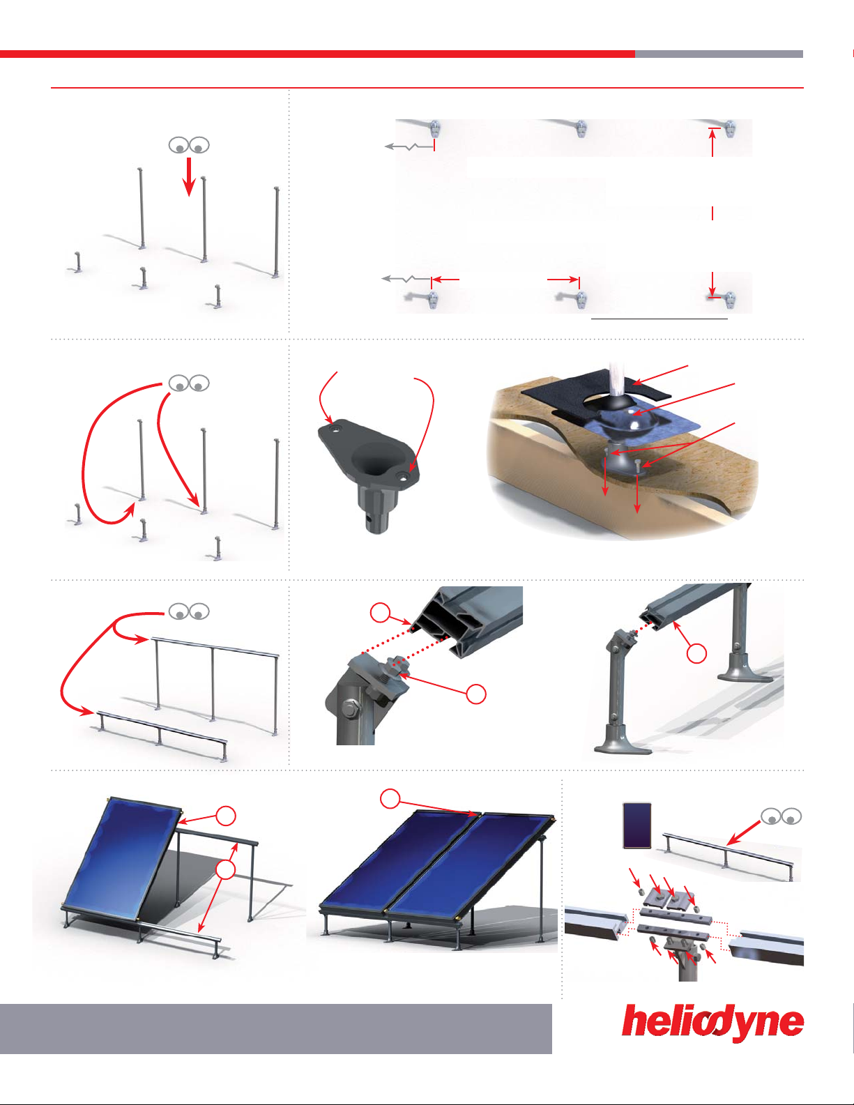
2.1. Rack Installation
2.1.0. Rack Leg Spacing
2.1.1. Rack Foot Mounting
2.1.2. Rail Mounting
2.1.3. Collector Mounting 2.1.4. Rail Splice (optional)
a
a
a
a
b
b
>2x
b
b2
3
4
5
1
1
1. Note rail orientation
2. Insert bolt head and flat washer into rail channel, lock washers and nuts compressing rail foot
1. Spacing for tilt is independent of collector size.
2. For other tilts the distance between front and rear mounting points =
(Rear Leg Height - Front Leg Height)
Tan (Gobi Tilt Angle)
3. Brace rails for first collector
4. Place first collector and install all (4) Helio-Clips.
Tighten bolts on Helio-Clips to engage locking serrated flange nut.
Roof Sealant
RACK MOUNTING INSTALLATION 11
SOLAR HOT WATER
5. Insert O-rings, tighten Unions. Take care not to crimp O-ring.
Do not use thread lock or sealants
*While lag screws are provided with most kits, consult the American Wood Council NDS 2005 for proper lag
screw specifications, or verify with a certified structural engineer, for each specific roof site. Heliodyne is not
responsible for mounting anchor integrity.
Heliodyne
recommends using
a long lasting thread
locker, such as Loctite
277, on rail splice kits.

FLUSH MOUNTING INSTALLATION
2
1
3
*000 001 Shown
2.2.0. FLSH Kit Components
2.2. Flush Mounting Overview
2.2.1. Flush Replacement Parts
ITEM CODE PART NUMBER DESCRIPTION QUANTITY
1 CLIP 000 000 40082 Helio-Clamp, 3/8-16 x 3/4 SS Bolt, Flange Nut (set of 4) 1 / Gobi
2RAIL 001 000
RAIL 002 000
40092
40090
2 x 1 Collector Mounting Rail - 51”, 1 x CLIP 000 000 set
2 x 2 Collector Mounting Rail - 102”, 2 x CLIP 000 000 set See Note 1
3
FLSH 001 000
FLSH 000 000
FLSH 000 001
FLSH 000 002
40087
40084
40085
40086
1 Collector Mounting Kit
Shingle Mount Hanger Bolt Kit
Shingle Mount Flange Kit
Tile Mount Kit
# Gobi + 1
4 RAIL 000 001 40089 Splice Kit for Joining Rails 1 Kit
E
F
H
G
N
D
3/8” - 16 x 1 SS Bolt11/2”- 13 SS Flange Nut 3/8” - 16 SS Flange Nut 1/2” - 13 x 1.25” SS Bolt
3/8” SS Flat Washer11/2”-13 x 6 SS Hanger Bolt Flush Mount Flange 3/8” x 4 SS Lag ScrewTile Bracket
Gobi Collector Clip Rail “L” Bracket 1/2” SS Flat Washer 3/8” x 2 SS Lag Screw
A D G
B E H LN
C F J
K
M
BD B
G
J
G
J
F
A D
C
A
A
K
M
L
B
FLSH 001 000
Single Collector Kit - No rail
FLSH 000 000
Shingle - Hanger Bolt Kit
FLSH 000 001
Shingle - Flashing Flange Kit
FLSH 000 002
Domed Terra-cotta Tile Kit
1May be substituted with integrated washer head bolt without notice
>2x
FLUSH MOUNTING INSTALLATION 13
SOLAR HOT WATER
36-50.25” MAX
36-45” MAX
Roof Sealant
75-90% Gobi Length
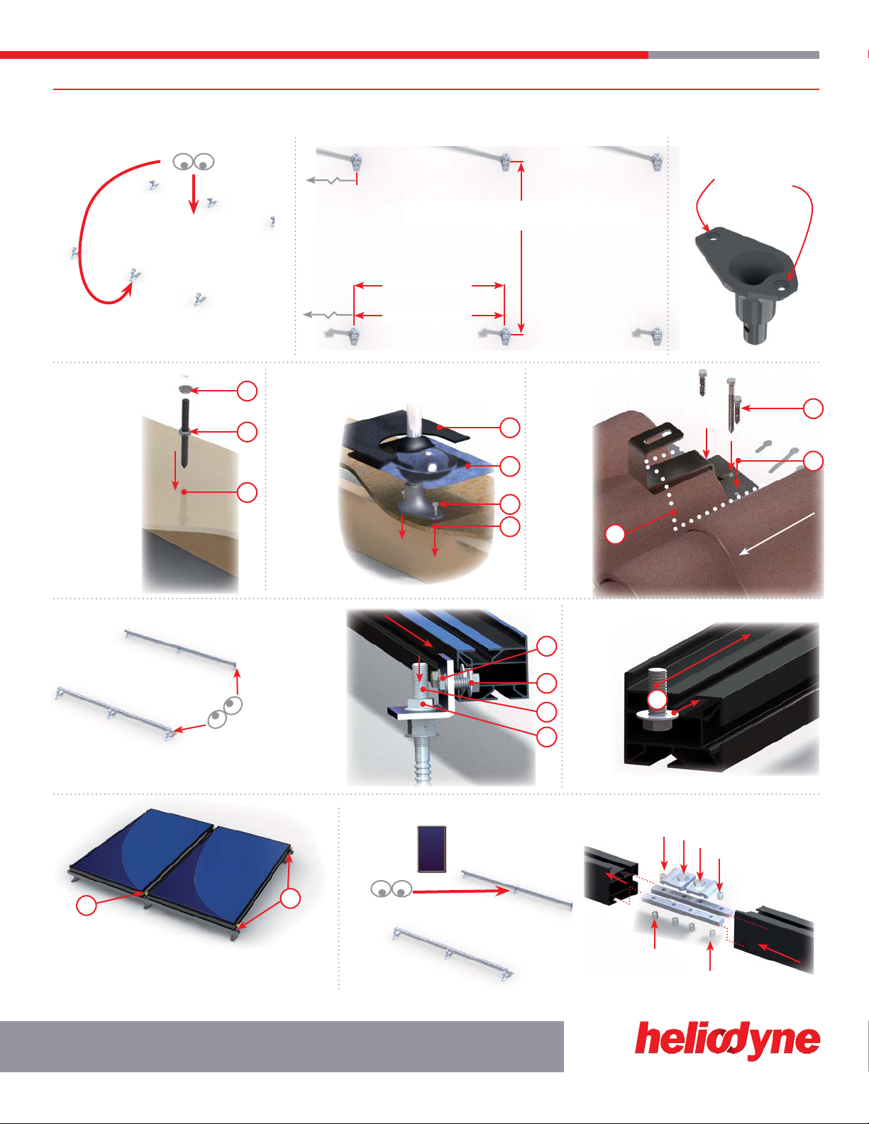
2.3. Flush Installation
2.3.0. Flush Foot Spacing
2.3.1. Hanger Bolt Mounting2
2.3.4. Rail Mounting 2.3.5. Collector Mounting
Roof Slope
2.3.6. Rail Splice (optional)
2.3.2. Flange Mounting22.3.3. Tile Mounting2
a
ab
b
3
2
1
1
1
1
2
3
3
1
2
2
2
3
3
3
4
2. Place collectors. Insert O-rings, tighten Unions. Take care not
to crimp O-ring. Do not use thread lock or sealants.
3. Place Helio-Clamps, and thread flanged nuts on exposed bolts
and tighten securely.
Heliodyne recommends using a
long lasting thread locker, such as
Loctite 277, on rail splice kits.
Locate a1.
rafter and drill
a 3/8” hole for
lag portion add
roof sealant; use
two flange nuts
backed against
each other to lag
bolt into roof
Use one2.
flange nut
face down for
compression seal.
Thread on3.
2nd nut with
flange upwards,
then Clip or “L”
bracket, then third
flange nut and
tighten.
Locate1.
a rafter and
use flange as
template to drill
two 3/8” holes
for lag screws;
add roof sealant
to holes and
flange.
Lag in2.
screws.
Place3.
OATEY 1-1/4”
flashing over
flange.
Replace4.
shingle over
flashing; follow
best roofing
practices to
ensure seal.
Remove1.
tiles. Locate a
rafter and use
tile bracket as
template to
drill three 3/8”
holes for lag
screws; add
roof sealant to
holes.
Lag in2.
screws.
Replace3.
tiles over
bracket; follow
best roofing
practices to
ensure seal.
With bolts, flange1.
nuts and washers
installed, slide all “L”
brackets onto each
rail into approximate
position of hanger
bolts, flash flange or
tile bracket; ensure the
washer is on the inside
of the rail flange for
proper strength.
Insert “L” bracket2.
onto each mount.
Tighten all nuts3.
and bolts for proper
strength.
Before1.
placing
collectors,
slide all
clamp
bolts and
washers into
approximate
position
on rails.
Ensure
washer is
inside the
rail channel
for proper
strength.
FLSH 001 000:
OTHERS:
2While lag screws are provided with most kits, consult the American Wood Council NDS 2005 for proper lag screw specifications, or verify with a certified structural
engineer, for each specific roof site. Heliodyne is not responsible for mounting anchor integrity.
HPAK INSTALLATION INSTRUCTIONS
3. HELIO-PAK INSTALLATION
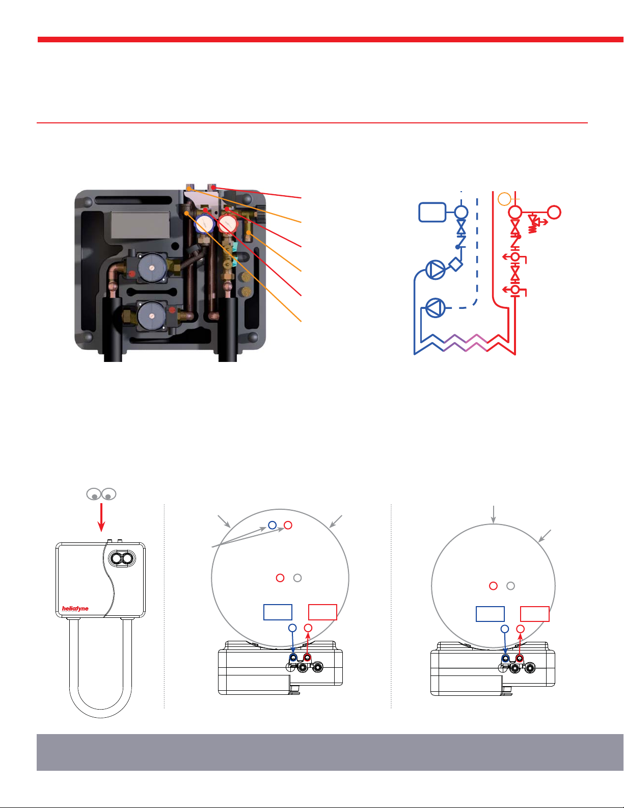
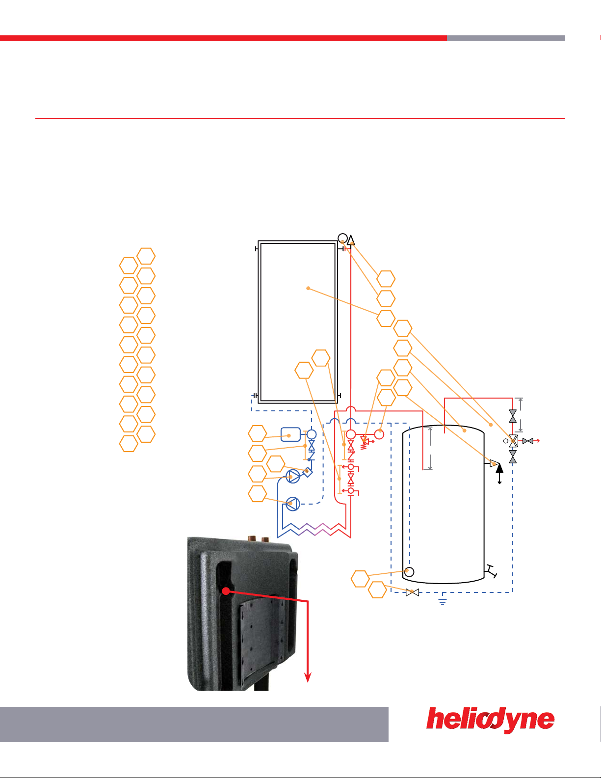
3.0. Helio-Pak Connections and Hydraulic Schematic
DHW Out (To Tank)
DHW In (From Tank)
Solar In (From Gobi)
PRV (Back Exit)
Solar Out (To Gobi)
Expansion Tank
T&P
T&P
DRAIN
SHWM
LONG
DIPTUBE
LONG
DIPTUBE SHORT
DIPTUBE
SHORT
DIPTUBE
Helio-Tank 119 Helio-Tank 80
DRAIN
Figure 3.0.-1: HPAK Connections Figure 3.0.-2: HPAK Hydraulic
Figure 3.1.-1: HPAK and Helio-Tank 119 Connections Figure 3.1.-2: HPAK and Helio-Tank 80 Connections
3.1. Tank Orientation
If using a Helio-Tank for installation, orient the proper solar connections in line with the HPAK connections to eliminate piping. On all tanks:
ensure proper dip tube length by inspection.
TT
P
M
T4

3.3.0. Storage Sensor Panel Removal and Installation 3.3.1. Collector
Sensor Installation
HPAK INSTALLATION INSTRUCTIONS 15
SOLAR HOT WATER
Helio-Tank 119
Tank Interconnect
CTOR 000 000
Helio-Tank 119
Standard Solar 119
Collector Sensor
Figure 3.2.-1: HPAK with Multiple Helio-Tank 119 Figure 3.2.-2: HPAK with Multiple Standard Solar Tanks
3.3. Sensor Installation
HPAK’s come with the necessary sensors pre-wired into the control; for more information see the separate control manual. The controls
require at least one tank sensor: on the bottom of the storage tank; the top tank sensor is optional. Most solar storage tanks have a stud near
the bottom for placement; the Helio-Tanks have studs for both top and bottom. If a specific area is not available, attach to a metal drain,
disconnected lower element, or use the cold in for lower tank sensor; use the hot out for a top tank sensor. The collector sensor must go on
the outlet header of the array.
For Pro models: the energy production is default set to calculate via the collector outlet sensor and the pre-installed flow meter temperature and flow sensor. For greater accuracy, install
an additional thermistor sensor just above the inlet to the heat exchanger and connect to T4 at the Delta-T Pro. See the hydraulic schematic on the opposite page for T4 position.
3.2. Plumbing Multiple Tanks
If using multiple tanks to achieve proper storage ratio, always use reverse return plumbing with the cold lines the longest, to ensure least
heat loss, and that each tank gets the same amount of circulation. For Helio-Tanks, use the 119 and connect all 2” side ports for increased
layering and higher performance.
HPAK INSTALLATION INSTRUCTIONS
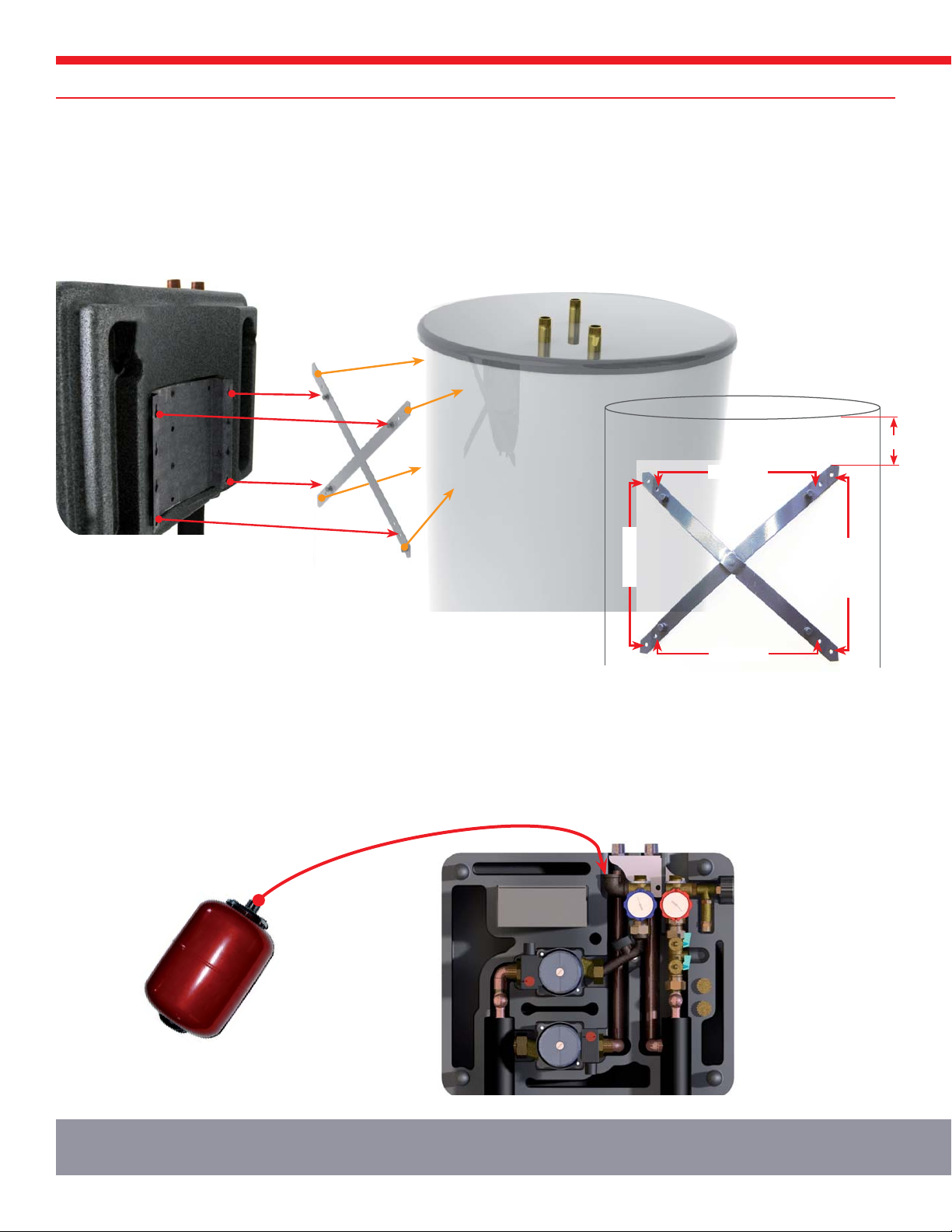
Figure 3.4.-1: HPAK Tank Mounting
6”
Wall Mount
Wall Mount
Tank Mount
Tank Mount
3.4. Helio-Pak Tank Mounting
Choose the mounting location for the HPAK. Using the X-Bracket supplied with the HPAK, measure and level a spot 6” down from the
desired position of the top of the HPAK foam. With the 4 self - tapping screws provided with the HPAK; on a tank use the inner mounting
holes on the curved part of the X, on a wall, use the outer mounting holes on the flattened part of the X. Align the top and bottom lugs on
the X with the top and bottom mating holes on the HPAK pre-mounted bracket and hang. Pull the HPAK down to lock in the lugs with the
HPAK bracket holes.
3.5. Expansion Tank Mounting
Helio-Paks come with a pre-sized expansion tank of bladder type. If the shipped expansion tank volume is less than 1/5th of the total
collector system fluid volume, contact Heliodyne to purchase the appropriate additional expansion.
Orientation of the bladder type tanks does not matter; any location using the expansion tank port and flex hose provided with the HPAK
is acceptable.
PLUMBING THE HPAK
4. PIPING
1
2
13
7
8
17
4
5
15
10
19
3
14
9
18
6
16
12
11
20
Figure 4.0.-1: Typical HPAK Installation Schematic
S
12"
18"
S
TT
P
M
M
4
12
5
13
6
14
15
16
7
18
9
8
17
10
11
3
2
1
S
S
M
M
P
Air Vent
Tempering Valve
Collector Sensor
Expansion Tank
Gobi Collector
Combo Valve: Cold
Filling Valve
Flow & Temp Meter
Combo Valve: Hot
Collector Pump
150 psi PRV
Storage Pump
Pressure Gauge
Tank Sensor
P & T Valve
Normally Open Valve
HSTG Solar Storage
Normally Closed Valve
Optional Isolation Valve
Bypass Valve
17
SOLAR HOT WATER
4.0. Connect the HPAK to the Tank
Insulate all hot water piping, as well as the final five feet of cold water storage inlet piping to a minimum R2.6. To enable backup heat
during solar system maintenance, isolation and shut off valves must be installed as recommended in installation schematics below. Use
dielectric unions when connecting piping to the storage tank nipples. When using the Helio-Tank, appropriately sized flex hoses can be
purchased from Heliodyne to avoid rigid copper plumbing. In the case of standard storage tanks, Heliodyne Gas Tank, or multiple tanks,
this is unavoidable.
When using the Helio-Tank, the DHW Cold is shared with the HPAK Cold. NEVER share the hot DHW and HPAK to prevent cold water
entering the hot line.
4.1. Connect the PRV to
Hose for Drain
The PRV comes with a barbed hose
fitting to attached a 1/4” ID hose for
funneling glycol to a bucket or drain, in
the rare even of release. Since this is
not part of a pressurized system, there
is no need to use expensive copper;
PEX or other high temperature suitable
plastics are okay here only.
In the even of a pressure release,
contact Heliodyne to discuss expansion
tank sizing.
*A combo valve is an integrated temperature gauge,
ball and check valve. The ball valve can be operated
as described in the components section 1.6.3 above
and is normally open.
12"
M
FLUID PLUMBING SCHEMATIC AND GUIDELINES
S
12"
S
18" 12"
12"
S
18"
M
M
M
HPAK
HPAK
From
Solar
Storage
To
Solar
Storage
From
Mains
HPAK HPAK
12"
Tank 115 VAC
Supply to
Delta-T Pro @
R3
M
T3
T2
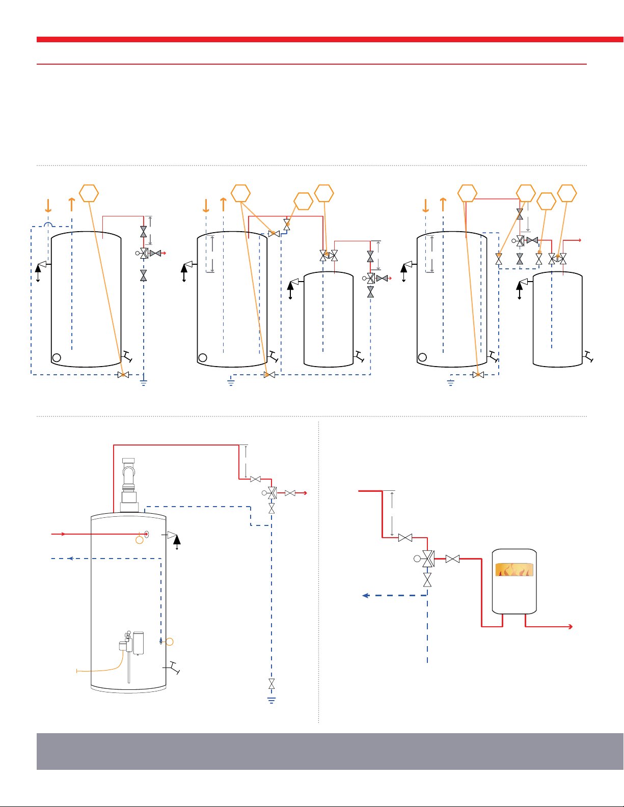
Figure 4.2.-1: Single Standard Tank Figure 4.2.-2: Dual Tank: Electric Backup Figure 4.2.-3: Dual Tank: Gas Backup
Figure 4.2.-4: HPAK PRO and Gas Figure 4.2.-5: Flow Thru Connection
4.2. Different Tank Schematics
If your tank is not here, contact Heliodyne with questions. Refer to the valve descriptions on the previous page. In accordance
with SRCC standard OG-300, all piping and valves must be labeled. Attach the waterproofed labels provided with this manual
to the appropriate components using zip-ties.
NOTE: For single tank electric systems: disconnect lower element for proper operation.
NOTE: For single tank gas systems: tanks with electric pilot and HP Pro ONLY
18 18 19 20 18 19
18 20

COLLECTOR FLUID PIPING
SOLAR HOT WATER
19
4.3. Gobi Collector Plumbing
Use only copper piping on the collector loop, solder to appropriate conditions in technical specifications. Always plumb in reverse return with
the longest line the cold, or use automatic balancing valves. Insulate piping for least losses; use rubber based insulation with environment
protection or Solar Pipe from Heliodyne. Gobi collectors can be put in portrait arrays of up to eight. Install bleed vents for filling at local high
points. Install a flexible arm or line on either side of the inlet and outlet to allow for header expansion.
4.3.0. Portrait Single Collector or Array 4.3.1. Single Horizontal Collector
4.3.2. Multiple Horizontal Collectors 4.3.3. Multiple Vertically Aligned Portrait Arrays
4.3.3. Multiple Horizontally Aligned Portrait Arrays
Min. Distance = Gobi Length * Sin (Tilt from Horiz.)
0.577
SYSTEM FILL AND STARTUP
5. COMMISSIONING
2
Flow Direction
1
3
5.0. Pressure Test and Clean Collector Loop
Before filling the collector loop with Dyn-O-Flo HD solution, pressure test the collector loop to check for soldering leaks. Remove the expansion
tank and cap off the exposed port, then fill the collector loop with water using the site hose and pressurize up to mains pressure 60 – 80 psig.
The filling station can also be used.
Monitor the pressure gauge for drops in pressure, inspect all joints. Turn the collector loop pump on to clean out residue; a 2% TSP solution
can be used. Fully drain the system to ensure correct glycol concentration upon final fill.
5.1. Calculate System Fluid Volume and Necessary Glycol Concentration
Find the total fluid capacity by adding in the volume of the collectors, HPAK and supply and return lines. With the total volume, use the
equation below to find out necessary gallons of glycol. Glycol concentration should be 40 – 60% for proper inhibitor concentration, regardless
of required freeze protection. A higher concentration than is required for freeze protection is recommended in case of errors in fluid
calculation.
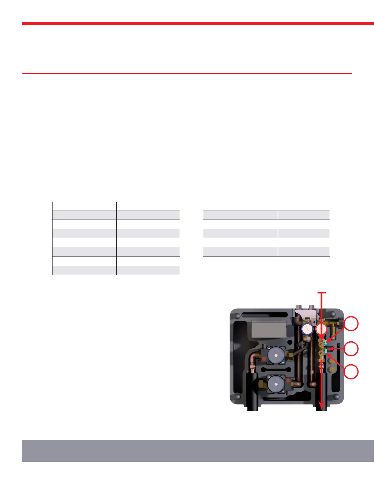
5.2. Fill System
The system can be filled easily with a filling pump from Heliodyne or manually. Consult
the manual with the filling pump for operation. Take care to use mineral spring water or
good quality tap water and only fill system when collector is cold. See installation notes
at the end of this manual for water requirements. Air vents or bleed vents at the high
points in the system help rid the system of air during filling only. If using any type of
automatic air vent, close vent after filling is complete as vents are not suitable for glycol
systems, or systems without continuously replaced fluids.
For use with a pump, connect pump supply hose to position 3 at right, and return hose
to position 2. Turn 1 so slot is horizontal, forcing return fluid out of 2. Turn on pump
to begin filling. After fluid begins to return back into tank from 2, close off valve at 2
and open 1. System will pressurize rapidly; monitor gauge and close off valve at 3 when
system reaches 40 – 60 psi. Turn off pump. Close off any bleed or air vents and run
system throughout the day. Check after a day cycle to ensure the cold pressure of the
system is at around 30 psig when cold. If further pressurization is necessary, hook up
pump supply to 3, turn pump on, open valve and pressurize back up.
For manual fill, pour in proper glycol and water mixture with a funnel into the top unused
header connection of Gobi. Pressurize with house water using the valve at position 3;
follow pressure guidelines as above. Hose nipples are provided, pre-set into the foam
next to the fill valve.
SYSTEM COMPONENT FLUID CAPACITY (GAL.)
GOBI 406 001 & 002 0.75
GOBI 408 001 & 002 0.83
GOBI 410 001 & 002 0.95
HPAK 016 000 & 001 0.80
HPAK 024 000 & 001 0.95
HPAK 032 000 & 001 1.00
HPAK 048 000 & 001 1.25
ASTM B88 COPPER TUBING GALLONS / 100’
Type M 1/2” (5/8” OD) 1.32
Type M 3/4” (7/8” OD) 2.68
Type M 1” (1-1/8” OD) 4.54
Type M 1-1/4” (1-3/8” OD) 6.80
Type M 1-1/2” (1-5/8” OD) 9.51
Type M 2” (2-1/8” OD) 16.5
Gallons of Dyn-O-Flo HD = Desired Concentration (%) * Total System Fluid (gal.) / 100
This manual suits for next models
13
Popular Solar Panel manuals by other brands

Battery Doctor
Battery Doctor 23140 instruction manual

oventrop
oventrop OKF-MQ25 Installation and operating instructions

Viessmann
Viessmann VITOVOLT Operating Instructions for the System User

esotec
esotec 101812 operating manual

Solimpeks
Solimpeks Wunder CLS 2510 instruction manual

Curtech
Curtech CT-K140 user manual


