- Output 1 (output 1):
Output voltage: 18 VDC, max. current load: 1.3 A
The output is switched via the button „ON/OFF“. The timer operation is
activated by pressing the button „Timer“. That means that the output 1
„OUTPUT 1“ is activated for approx. 10 minutes every hour. This mode
of operation is reasonable in particular in case of inadequate insolation.
The output voltage is rmly set to 18 V.
- Output 2 (output 2):
Output voltage: 6 VDC, max. current load: 0.7 A
The output is switched via the button „ON/OFF“. The output voltage is
rmly set to 6 V.
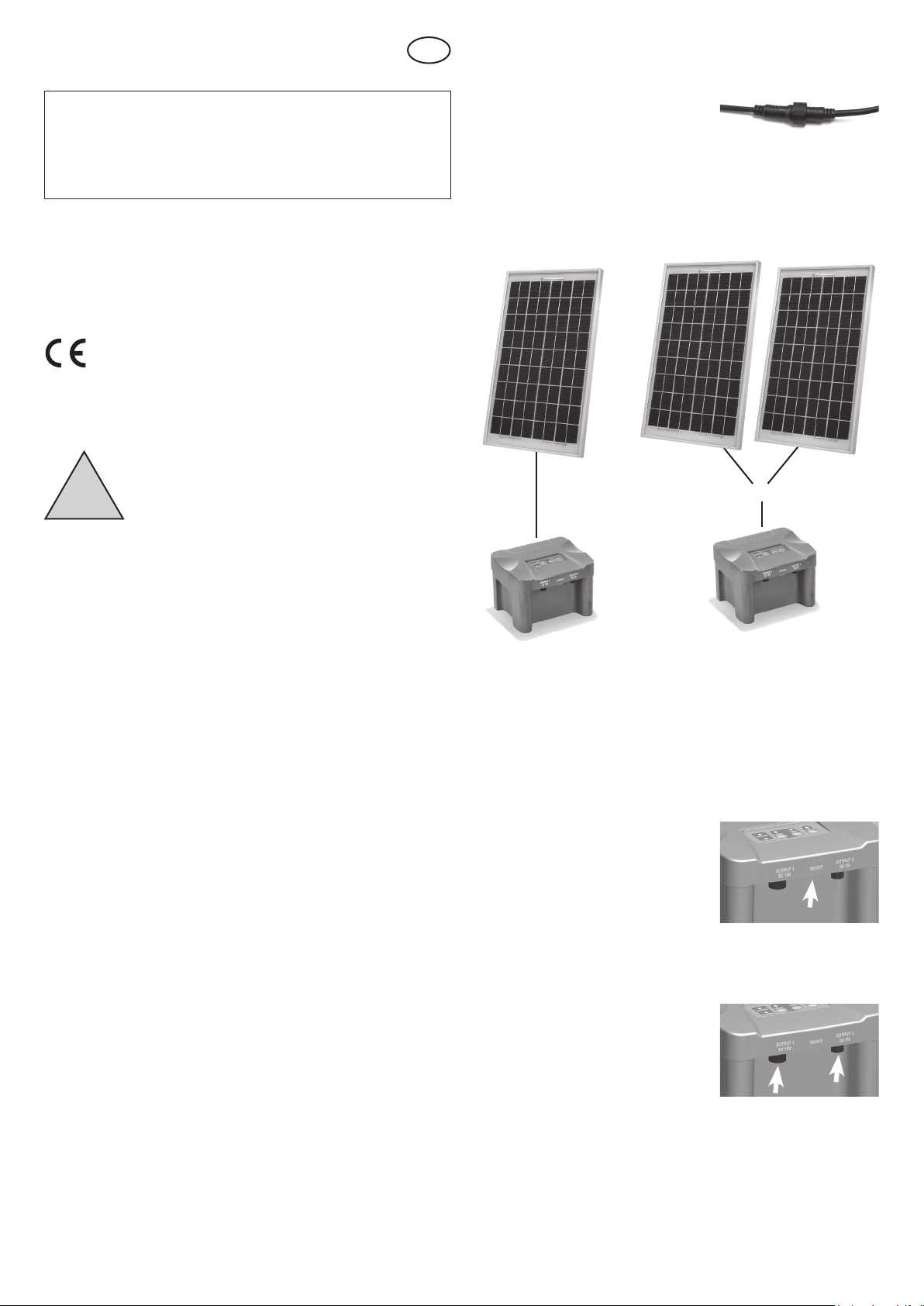
Note: The outputs are connected by means of system plugs.
Corresponding distributors and/or extensions are available as
accessories. The protective caps at the plug-in connections have to
be tightened. Not used outputs have to be closed by means of the
corresponding protective caps. Please do not apply force when plugging
in!
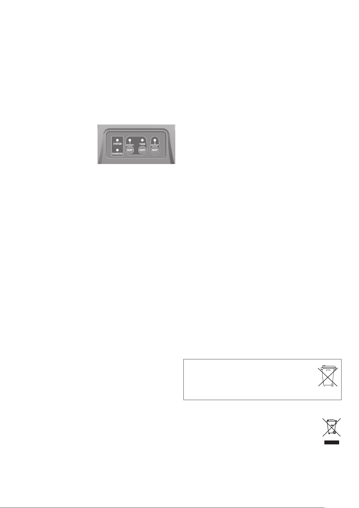
5. Indicator LEDs
LED „SYSTEM“:
green: Accumulator charged and outputs may be
switched on.
red/ green 2x ashing: Accumulator in full charge.
See item: 6.
red: The accumulator is discharged and the outputs
are (OUTPUT) switched off.
LED „CHARGING“: yellow: Accumulator is charged
yellow ashing: Accumulator is fully charged and on
trickle charging.
LED „OUTPUT 1“: green: Output 1 is switched on.
green ashing: Short circuit on output 1.
LED „TIMER“: green: Timer mode is activated.
LED „OUTPUT 2“: green: Output 2 is switched on.
6. Charging process
The LED „System“ will shine red if the accumulator was discharged the
previous evening.
In the morning and when the sun is shining, the charging of the accumulator
will have priority. As soon as the accumulator is charged, the „Charging“ LED
will light up yellow. The charging timer is started when the accumulator reaches
the voltage of 12.7 V and the accumulator will be fully charged for another (30
min. 7 Ah box) 50 minutes (12 Ah box) . The LED „System“ ashes every 10
seconds 2 x from red to green. The outputs (Output) are switched on after
those 50 minutes.
7. Exchanging the accumulator
We recommend exchanging the accumulator approx. every 2 years. A new
identical in construction accumulator is available from the manufacturer or
dealer.
Proceed as follows if you want to exchange the accumulator:
1. Put the main switch (SYSTEM ON/OFF) at the front side of the accumulator
box in the position „OFF“ and unplug all plugs.
2. Turn the accumulator station upside down and loosen the bottom four
screws.
3. Then turn the accumulator box back again and carefully remove the lid.
4. Loosen the + Pole and - Pole connection on the accumulator.
5. Remove the accumulator from the case and insert a new identical in
construction accumulator.
6. Put the cable lugs back onto the poles of the accumulator. In doing so, please
pay attention to the color of the cables: positive pole (red) and negative
pole (black).
7. Close the case in reverse order.
Note: Please only use an identical in construction accumulator with identical
voltage and capacity.
Note: The old accumulator has to be disposed of in an environmentally sound
way. For this purpose, please contact you local authorities, public collection
points or your dealer.
8. What to do during the winter
Fully charge the accumulator in the accumulator box. Use a sunny day for this
purpose and put the switch „SYSTEM ON/OFF“ in the position „OFF“.
Only store the accumulator box (during the winter) in a fully charged state in
a frost-free room. At sunny days, the accumulator box may occasionally be
connected to the solar module for charging purposes. This enables an as long
as possible lifetime of the accumulator.
If you want to operate the accumulator box during the winter, e.g. in connection
with a pond aerator or a string of LED lights (available as accessories), then it is
possible to store the box outdoors. Please pay attention to the fact that the site
is free of snow and that the accumulator box is not under water when thawing
begins. A frost protection for the accumulator box would be advantageous.
9. Troubleshooting
- LED does not shine green despite insolation but the yellow LED shines.
1. The accumulator is not charged sufciently and has not achieved the restart
threshold. The charging process may take several hours when the insolation
is insufcient. (see item 6).
2. Accumulator is exhausted! The accumulator should be exchanged approx.
every 2 years. Please see item 7 of this instruction.
- LED does not shine green despite insolation; when the switch „SYSTEM
ON/OFF“ is switched off and on again, the pump starts to run and the
green LED shines.
1. The accumulator had not achieved its restart threshold. After the switching off
and on of the system, the electronics is reset and the connected consumers
are supplied with energy without waiting for the restart threshold. This is
an absolutely normal process and does not constitute a defect (please see
item 6). However, this method should not be applied because it has negative
effects on the lifetime of the accumulator.
- LED does not shine green despite insolation. The LED System ashes
green two times at an interval of 10 seconds.
1. The accumulator is in the full charge phase. Please pay attention to item 6.
- The green LED above output 1 ashes.
1. There is a short circuit or overcharge on output 1. Please check the
connected device and all plug-in connections (in particular the pumps and
the LED lighting) for tightness.
2. Check the cables for damages or bites by animals.
- The yellow LED „CHARGING“ shines but nothing else works.
1. Is the switch „SYSTEM ON/OFF“ switched on (position ON)?
2. If yes, then switch off the switch „SYSTEM ON/OFF“ for approx. 1 minute
and then on again. This will reset the control electronics.
10. Technical data:
Type Accu box 12 V /7 Ah Accu box 12 V/ 12 Ah
Art.-No: 101816 101812
Max. module capacity: 50 Wp 50 Wp
Charging timer: 30 min. 50 min.
Protection class: IP 44 IP 44
Temperature range: -15 to +30°C -15 to +30°C
Accumulator: PB 12 V/7 Ah PB 12 V/ 12 Ah
Replacement accumulator: 901034 901032
(www.esotec.de)
Outputs:
Output 1: DC 18V/ max. 1.3A DC 18V/ max. 1.3A
Output 2: DC 6V/ max. 0.7A DC 6V/ max. 0.7A
5 m extension cable solar module: 101738 101736
5 m extension cable “Output 1”: 101738 101736
5 m extension cable “Output 2”: 101740 101740
WARNING of trip hazard! Please lay the connection cable so that it does not
constitute a trip hazard!
Disposal:
Dear customer,
please cooperate in avoiding waste. When you intend to dispose of the
product in future, please consider that it contains valuable raw materials
suited for recycling.
Therefore, do not dispose it of with domestic waste but bring it to a col-
lection point for the recycling of waste electrical and electronic equipment.
Thank you very much for your cooperation!
Manufacturer:
esotec GmbH - Gewerbegebiet Weberschlag 9 - D-92729 Weiherhammer
Tel.-Nr: +49 9605-92206-0 Fax.-Nr: +49 9605-92206-10
Internet: www.esotec.de WEEE-Nr: DE59284711
Copyright! esotec GmbH
Battery take-back
- Batteries must not be discarded into domestic waste.
- The consumer is legally required to return batteries after use, e.g. to
public collecting centers or to battery distributors.
- Contaminant-containing batteries are labeled with the sign “crossed-out
trashcan“ and one of the chemical symbols. Used batteries should be dis-
posed environmentally friendly and should not be discarded into domestic
waste. Your dealer is legally required to take back old batteries. Pb