Conergy SunTop Trapeze User manual

Conergy SunTop Trapeze
www.conergy.com
Installation manual

Table of Contents
2 Installation manual Conergy SunTop Trapeze
ENGLISH
Table of Contents
1 Introduction 1
1.1 Short description 1
1.2 Intended use 1
1.3 Standards and guidelines 1
1.4 About these instructions 1
2 Safety 2
2.1 Basic safety information 2
2.2 Information regarding working on roofs 2
2.3 Warnings 2
2.4 Operator‘s responsibilities 3
3 Technical description 4
3.1 System overview 4
3.2 Scope of delivery 5
3.3 Technical specifications 6
4 Planning the module area 7
5 Important installation information 8
5.1 Conditions of use 8
5.2 Preparation 8
5.3 Mounting aids and required tools 8
5.4 Grounding the mounting system 8
6 Install the system 9
6.1 Using the EPDMs 10
6.2 Placing and aligning the base rails 10
6.3 Positioning of the trapezoidal side fixations 11
6.4 Positioning of the trapezoidal top fixation 12
6.5 Mounting the base rails 12
6.6 Securing the base rails against excessive
slipping 14
6.7 Connecting the base rails 14
7 Mounting the modules 15
7.1 Quickstone installation 15
7.2 Anti-slip protection for portrait orientation 16
7.3 Fixing the outer modules of each row 16
7.4 Fixing the inner modules of each row 17
7.5 Installing further rows of modules 17
8 Distinctive features when installing
the modules in landscape orientation 18
8.1 Correct alignment of the base rails 19
8.2 Installation of the base rails and modules 20
Conergy SunTop Trapeze - innovative solution for metal roofs

1 Introduction
Conergy SunTop Trapeze Installation manual 1
ENGLISH
1 Introduction
1.1 Short description
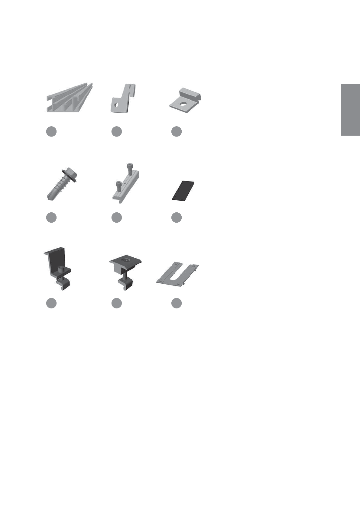
The SunTop Trapeze flat roof system is a sturdy frame sys-
tem for mounting PV modules on trapezoidal sheet metal
roofs. It consists of aluminum base rails and all necessary
small parts to install the modules to the rails and con-
necting the components to each other. Both portrait and
landscape mounting of the modules are possible.
1.2 Intended use
The on-roof system SunTop Trapeze is to be used for the
installation of PV modules only. Any other use is consid-
ered improper. Please follow the instructions in this manual
carefully. Mounting Systems is not responsible for damage
that results from improper installation. Be sure to follow the
safety and use guidelines closely.
1.3 Standards and guidelines
When planned correctly, SunTop Trapeze fulfills the follow-
ing standards and directives:
• Eurocode 9 — DIN EN 1999-1-1: Design of aluminum
structures
• Eurocode 1 — DIN 1055 — Actions on structures
• DIN 18807-3 Trapezoidal sheeting in building; trapezoidal
steel sheeting; structural analysis and design
• DIN 18807 Trapezoidal sheeting in buildings - Part 9:
Aluminium trapezoidal sheeting and their connections;
application and construction
In addition, every installation must be in compliance with
the following codes/rules:
• VDE 0100 – 712 ; IEC 64/1736. Installation of low-voltage
systems
• VDE 0185 Serie, IEC 81/335. Lightning protection
1.4 About these instructions
Subject
The purpose of this manual is to provide instructions for the
installation of the on-roof system SunTop Trapeze.
The illustrations in this manual show the installation for
framed modules in portrait orientation. The installation in
landscape orientation is dealt separately in section 8.
Users
This manual is written specifically for qualified installers
who have undergone instructions by the operator and have
basic mechanical and trade skills.
Orientation aids
The following aids will improve the readers’ understanding
when using this manual:
Symbols
Shows detail and additional information for
handling procedures.
Useful Tips
Simplifies handling procedures and contributes
to the success of the installation.

2 Safety
2 Installation manual Conergy SunTop Trapeze
ENGLISH
Indicates a severe and unusual risk
that, if ignored, could lead to seri-
ous injury or death.
Indicates a potentially hazardous
situation that could lead to serious
or moderate bodily injury and prop-
erty damage.
Indicates a potential hazard that
could lead to property damage.
2 Safety
2.1 Basic safety information
The following basic safety information and warnings are an
important part of this manual and needed for safe handling
of this product:
• Ensure that the product meets local code requirements
prior to mounting and installation.
• Ensure the building must meet the increased code
requirements resulting from the PV unit prior to mounting
and installation.
• Comply with the relevant safety regulations.
• Wear a hard hat, protective gloves and safety shoes.
• A second person must be present during the entire in-
stallation, to provide assistance in the case of accident.
• Keep a copy of this installation manual in the immediate
vicinity of the system.
2.2 Information regarding working on roofs
When working on roofs:
• Always follow accident prevention regulations, and if
necessary, install guards to protect against falling com-
ponents.
• Accident prevention regulations require a safety harness
or protective scaffolding be used.
• Observe valid local safety regulations.
• Test and verify the load-bearing capacity of all relevant
components prior to walking on the roof.
• Use fall protection equipment.
• Use protective equipment, even for simple and quick
tasks.
• Always use appropriate lifting equipment. Never carry
material up the ladder.
2.3 Warnings
The warnings listed in this manual indicate safety-relevant
information. They include:
• Warning symbols
• Key words to indicate the risk level
• Information about the type and source of the risk
• Information about possible consequences if the danger
is ignored
• Measures for avoiding risk and preventing injuries or
property damage
The key words in the warnings always indicate one of the
following risk levels:
WARNING
CAUTION
DANGER

2 Safety
Conergy SunTop Trapeze Installation manual 3
ENGLISH
2.4 Operator‘s responsibilities
The system operator must fulfill the following safety-related
obligations:
• Ensure that only persons with basic mechanical and
trade skills should be installing this system.
• Ensure that responsible persons must be able to recog-
nize and assess all possible dangers involved in the work
assigned to them.
• Ensure that the responsible persons are familiar with all
system components.
• Ensure that the installation manual is readily available
during the assembly. These installation manual is an
integral part of this product.
• Ensure that a project related design layout exists.
• Ensure that the installation manual and especially the
warnings are read and understood by the responsible
persons prior to assembly.
• Ensure that the permissible conditions of use (see sec-
tion 3.3) have been upheld. Mounting Systems will not be
responsible for damage which results from a violation of
these conditions.
• Ensure that the roof construction has the required load-
bearing capacity.
• Ensure that the durability of the mounted connections
and the roof attachments are guaranteed.
• Ensure that appropriate lifting equipment must be used
for the mounting work.
• Ensure that Mounting Systems components are to be
used, both for the initial installation and for eventual
maintenance or repair later on, otherwise all guarantees
will be void.

c
f
e
b
d
a
3 Technical description
4 Installation manual Conergy SunTop Trapeze
ENGLISH
3 Technical description
3.1 System overview
All system components are listed below. The design of the
individual system components may vary.
They are dependent on:
• roof type
• module type
• number of modules
• the onsite conditions
Please note:
This illustration shows the portrait orientation of the
PV modules. Base rails that are 40 cm long are used for
landscape orientation.
In addition, the system overview shows the possibility of
fastening the base rails on the side and on the top on the
high beads of the corrugation.
a Base rail
b Trapezoidal side fixation
c Trapezoidal top fixation
d Inter-module clamp
e Module end clamp
f EPDM

b
e
h
c
f
i
a
d
g
3 Technical description
Conergy SunTop Trapeze Installation manual 5
ENGLISH
3.2 Scope of delivery
Following the descriptions of all
SunTop Trapeze components that may
be included in delivery are listed.
The exact delivery contents and the
quantities of the individual system
components are based on your order.
a Base rails
b Trapezoidal side fixation with
Alu-Fixband seal
c Trapezoidal top fixation
d Drilling screw with gasket (6x25 mm)
e Splice preassembled for framed
modules
f EPDM 80 mm (trapezoidal top fixation) or
40 mm (trapezoidal side fixation)
g Z -Module end clamp
h Inter-module clamp
i Grounding clip (Weeb clip)

3 Technical description
6 Installation manual Conergy SunTop Trapeze
ENGLISH
3.3 Technical specifications
1 Not suitable for sandwich roofs.
2 After contacting Mounting Systems and a verification of the codes, thinner sheet metal thicknesses may be possible.
3 In case of a very low bead height (below 20 mm) a holder can be screwed on top of the trapezoidal sheet, alternative to the
trapezoidal side fixation, which is fixed laterally.
4 Depending on the location, building, selected fixing devices and the module type, other values may vary. With the SunTop Trapeze design tool,
you can calculate the permissible maximum values for any system quickly and easily.
5 Because of the expected thermal expansion due to temperature differences and the resulting stress on the rails, we recommend a
maximum length of 12 m per module row.
Application areas Pitched roof – on-roof
Roof covering Trapezoidal sheet metal 1
Min. sheet thickness 0,63 mm 2
Min. bead height Free 3
Roof pitch Up to 20° 4
Height of building Up to 20 m 4
PV module Framed
Module alignment Portrait, landscape
Size of the module field Free 5
Position of the module field Free
Possible height leveling Up to 5 mm
Distance between rail fixation Depending on the load situation (automatic verification by the design software)
Standards Eurocode 1 – DIN 1055 – Actions on structures
Eurocode 9 — Design of aluminum structures
Profiles Extruded aluminum profiles (EN AW 6063 T66)
Rail fixation Aluminum (EN AW 5754)
Small parts Stainless steel (V2A)
Color Aluminum, cold pressed

2
1
3
4
5
4 Planning the module area
Conergy SunTop Trapeze Installation manual 7
ENGLISH
4 Planning the module area
The following gives the spacing of the roof mounts for in-
stalling modules that are in a portrait orientation. The spac-
ing for landscape orientation can be found in section 8. The
trapezoidal fixation must be mounted at specific distances
depending on the material, thickness of the trapezoidal
sheet metal, the spacing of the high bead of the corruga-
tion, consideration of the edge area and the further general
conditions* (a tool is used for the design).
Taking the above mentioned points into consideration,
the trapezoidal fixation must be placed so that they are as
close as possible to the module clamps.
When positioning, please note that
• the given dimensions are guidelines.
• the dimensions of the trapezoidal sheet metal and the
high bead of the corrugation define the true horizontal
spacing.
* A design in accordance with the local conditions according to
Eurocode 1-DIN 1055 / Eurocode 9-DIN EN 1999-1-1 is required.
1. Height of the module field: number of modules in the vertical x module height
2. Width of the module field: Number of modules in the horizontal x (module width + 19 mm) + 50 mm
3. Spacing of the guide rails in the vertical (in accordance with the clamping points defined by the module manufacturer): approx. the quarter
points of the modules = 1/2 x module height
4. Spacing of the trapezoidal fixations in the portrait orientation: according to the plan, depending on the trapezoidal sheet metal and the
structural analysis*
5. Spacing between the modules = 17 – 19 mm

5 Important installation information
8 Installation manual Conergy SunTop Trapeze
ENGLISH
5.3 Mounting aids and required tools
You will need the following tools to mount the frame
system:
• 6 mm Allen key
• Cordless screwdriver
• Attachment for cordless screwdriver, hexagonal
8 mm bit
• Angle grinder with metal disk
• Chalk line
• Spirit level
• Folding rule/measuring tape
• Lifting device
(e.g. attachable work platform, shoulder straps)
• Suction cup tool
• Spacing template if applicable
(for landscape installation)
5.4 Grounding the mounting system
The potential equalization between the individual system
components must follow the respective country-specific
regulation. A possibility of grounding the SunTop Trapeze
system is shown in the following picture. The cable gauges
as well as the general grounding concept are not included
in this guide and must be calculated and/or created by the
installer in accordance with the applicable standards and
guidelines. Professional grounding methods other than the
ones given here are also possible.
5 Important installation information
5.1 Conditions of use
The on-roof system SunTop Trapeze with its different rail
and roof mounting variations is designed for different
maximum loads in accordance with Eurocode 1: Actions on
structures.
The suitability of the material must be checked for each
system, with the help of the SunTop Trapeze design tool.
5.2 Preparation
Mounting Systems recommends that you familiar-
ize yourself with the local conditions prior to ordering
SunTop Trapeze.
Pay special attention to the following:
• the roof configuration (e.g. high corrugation bead spacing
and bead height)
• the thickness as well as the material of the trapezoidal
sheet metal
• the quality and the condition of the trapezoidal sheet
metal
• the adequate fixation of the trapezoidal sheet metal to
the substructure
CAUTION
Material damage due to inadequate fastening
Inadequate fastening of the trapezoidal sheet metal roof to the substructure can lead to material
damage.
• Check to see whether the fastening of the trapezoidal sheet metal to the substructure is adequate.

6 Install the system
Conergy SunTop Trapeze Installation manual 9
ENGLISH
Grounding of the individual rail rows:
• Fasten a cable lug by means of a drilling screw to each
row of rails. It can be fastened to the side channel of the
base rails. When positioning the cable lug, make sure
that it does not adversely affect the use of the trapezoidal
fixations, splices or module clamps.
• Connect the individual rows of rails.
Low-resistance connection between the modules and base
rails:
Unless otherwise specified by the module manufacturer,
the modules for SunTop Trapeze can be connected con-
ductively to the rails in the following way:
• Slide a grounding clip (weeb clip) onto the still uninstalled
module clamp (only inter-module clamps).
• Mount the module clamps as usual, but make sure the
grounding clip (weeb clip) is correctly inserted at the
same time. The correctly inserted clip sits between the
base rail and the module frame. The 4 noses protrude
into the rail channel.
6 Install the system
The following pages contain all the operations for installing
the SunTop Trapeze in the correct order. Trapezoidal fixa-
tions are used for the assembly of the base rails. They can
be fixed either to the side of the high bead of the corruga-
tion or on the high bead itself. Define and mark the position
of the individual rows of rails on the roof before beginning
assembly.
DANGER
Danger to life from falling and falling parts
Falling from the roof or being struck by falling parts may result in critical injuries.
• Protect yourself against falling.
• Do not remain in the danger zone.
• Wear a hard hat.
• After the assembly is complete, check to make sure that the frame system and the modules
are secure.
CAUTION
Material damage by stepping on
frame components
Stepping on the roof fixations or base
rails may damage the underlying mate-
rial, e.g. the trapezoidal sheet metal.
• To avoid damaging the underlying
material, do not stand on or put any
weight on the frame components.

6 Install the system
10 Installation manual Conergy SunTop Trapeze
ENGLISH
6.1 Using the EPDMs
Installation:
• Define the position of the base rails
on the trapezoidal sheet metal,
taking into account the allowable
clamping area of the used PV mod-
ules.
• Use the chalk line to mark the
position of the EPDM on each high
bead.
• Stick an EPDM strip onto each high
bead on which the base rails rests.
EPDM 40x20x1 mm is used for as-
sembling the base rail with the side
fixations. EPDM 80x20x1 mm is used
for the top fixations.
Make sure that the base rails do not
rest on calottes. It might be neces-
sary to adapt the positions of the base
rails. 6.2 Placing and aligning the base rails
Positioning the base rails onto the roof to interpret and define the possible cuts.
The connected series of rails should not exceed a length of 12 m. The required
total railway length is determined by the width of the module area (see point 4).
Make sure that the maximum cantilever of 17.5 cm is not exceeded (if necessary,
cut rails or use splices).
The spacing of the rails to each other is defined by the size of the PV module
(see section 4).
Base rails that are 40 cm long are used for landscape mounting (see section 8).
Installation:
• Place the base rails on the applied
EPDM.
• Using a level, align the profiled rails
to each other.
Positioning the EPDMs with the help of a chalk line
Aligning and placing the profiled rails
Material damage due to incorrect assembly
Resting the base rails on the trapezoidal sheet metal without
EPDM can lead to damaging the roofing material.
• Stick an EPDM strip onto every high bead that comes into
contact with the base rails.
CAUTION

6 Install the system
Conergy SunTop Trapeze Installation manual 11
ENGLISH
6.3 Positioning of the trapezoidal side fixations
Installation:
• Insert the trapezoidal side fixation in the side channel.
• Press the trapezoidal side fixation against the side of the
high bead and make sure that it rests uniformly and is
hooked into the side channel of the base rail correctly.
• The trapezoidal side fixations are fastened opposite from
each other on the high bead.
Positioning of the trapezoidal side fixation for bead
heights ≥ 20 mm
Material damage due to incorrect assembly
Incorrectly assembled trapezoidal side fixations may
rip out.
• When fastening the trapezoidal side fixations, al-
ways make sure that the fixation is seated correctly
in the channel.
CAUTION
The following points must be considered when
installing the trapezoidal side fixations till the verge
of the roof.
• It is not possible to place the trapezoidal side
fixation set off to one side.
• Fasten the first trapezoidal side fixation on the
high bead as described above.
• The second trapezoidal side fixation can only be
fastened opposite on the same side of the high
bead.
• To do this, pull the sealing off the trapezoidal
fixation and stick it on the opposite side.
A piece of EPDM can also be used.
TOOL

6 Install the system
12 Installation manual Conergy SunTop Trapeze
ENGLISH
6.4 Positioning of the trapezoidal top fixation
Installation:
• Place the trapezoidal top fixation onto the EPDM and at-
tach to the profiled rail as shown in above picture.
• Place the opposite trapezoidal top fixation.
Take into account that longer EPDM pieces that are
80x20x1 mm must be used.
6.5 Mounting the base rails
Installation:
• Fasten the trapezoidal fixation on the side or top with the
supplied 6x25 mm drilling screws with gaskets.
• Do not over-tighten the screws.
• The torque setting of the cordless screwdriver is depend-
ent on the thickness and the material of the trapezoidal
sheet metal.
Positioning of the trapezoidal top fixations for bead
heights < 20 mm
Positioning of the 6x25 mm drilling screw with a gasket
Correct fit of the trapezoidal top fixation
Material damage due to incorrect assembly
Incorrectly assembled trapezoidal fixations may rip
out.
• When fastening the trapezoidal fixation, always
make sure that the fixation is seated correctly on
the base rail.
CAUTION

6 Install the system
Conergy SunTop Trapeze Installation manual 13
ENGLISH
Mounted side trapezoidal fixation
Mounted top trapezoidal fixation
Building damage through leakage
Incorrectly installed trapezoidal fixation and drilling
screws can cause leaks.
• Be sure the fixation is evenly aligned on the high
bead.
• Make sure that the seal rests cleanly between the
high bead and the trapezoidal side fixation.
• Make sure if installing the trapezoidal top fixation
the EPDM fits correctly underneath.
Material damage due to incorrect assembly
Incorrectly installed drilling screws may rip out.
• Do not over-tighten the drilling screws.
CAUTION
CAUTION
Damage to the building and the PV system
through incorrect frame installation
Incorrect spacing of the trapezoidal fixation can
cause damage to the building and the PV system.
• When fastening the base rails with the trapezoidal
fixations select the spacing corresponding to the
tool configuration.
• Comply with the different configurations for the
spacing of the trapezoidal fixations that are to be
placed at the edge and in the field area.
CAUTION

6 Install the system
14 Installation manual Conergy SunTop Trapeze
ENGLISH
6.6 Securing the base rails against excessive slipping
The base rails should be secured in their position. The used
trapezoidal fixations allow the base rail an expansion pos-
sibility, as e.g. arise from high temperature differences. To
secure the position and still allow an expansion of the base
rails, they have to be secured with two drilling screws from
the side. Rows of rails that are connected together with
the Splice only have to be secured once with two drilling
screws. Each individual rail must be equipped with two
drilling screws.
Installation:
• Two 6x25 mm drilling screws (identical to the screws for
fastening the trapezoidal fixations) are used to secure the
base rails.
• Screw the drilling screws into the side of the base rail to
the right and left of the trapezoidal fixation at a distance
of approx. 2 cm.
• Ensure that the use of the module clamps or splices is
not impeded by the drilling screws.
6.7 Connecting the base rails
A splice is provided for connecting individual rail series.
They can also be used for grounding individual base rails
together.
Installation:
• Put the splice into the Quickstone channel from the top.
• Make sure it is seated correctly in the channel.
• Tighten the first M 8 Allen screw (torque=8 Nm) with the
Allen wrench.
• Tighten the second M 8 Allen screw (torque=8 Nm) with
the Allen wrench.
The connected series of rails should not exceed 12 m in
length.
From that point on, an expansion joint (approx. 5 cm) must
be used. Do not install any modules over an expansion
joint.
Profiled rail connection with Splice for framed PV modules

7 Mounting the modules
Conergy SunTop Trapeze Installation manual 15
ENGLISH
Installation:
• Loosen the Allen screw before the
installation, without removing it
completely. The Allen bolt must not
protrude past the bottom of the
Quickstone.
• Insert the Quickstone into the chan-
nel. The shape of the Quickstone
fits precisely into the profile of the
Quickstonechannel.
• Tighten to 8 Nm with the Allen
wrench.
Danger to life from falling and falling parts
Falling from the roof or being struck by falling parts
may result in critical injuries.
• Protect yourself against falling.
• Do not remain in the danger zone.
• Wear a hard hat.
• After the assembly is complete, check to make
sure that the frame system and the modules are
secure.
DANGER
7 Mounting the modules
The modules are successively installed onto base rails. It is
recommended to start on one side of the module field. The
Modules in the bottom row can be equipped with anti-slip
protection. Inter-module clamps and module end clamps
are used to fasten the modules. The module end clamps
can each are used to hold one module. The inter-module
clamps are positioned between two modules.
7.1 Quickstone installation
Quickstones are used for the assembly of the modules.
A Quickstone is a special profiled nut that is used to fasten
the module clamp in the base rail. For the installation, you
only need an Allen wrench (6 mm). You can insert Quick-
stones into the rail channel of the base rail from
the top.
CAUTION
Material damage due to incorrect assembly of the Quickstones
Incorrectly installed Quickstones may rip out of the profile.
• Install all Quickstone connections in accordance with the instructions.

7 Mounting the modules
16 Installation manual Conergy SunTop Trapeze
ENGLISH
7.2 Anti-slip protection for portrait orientation
Installation:
• The anti-slip protection is only necessary for modules in
the bottom row.
• Install one anti-slip protection (M 6 x 20 mm bolt with nut)
in each of the lower holes of the module.
• Place the first module of the bottom row so that the
anti-slip protection sits in the rail channel of the lowest
rail row.
7.3 Fixing the outer modules of each row
Installation:
• Insert the Quickstone of the module end clamp (Z-mod-
ule end clamp here in the example) in the rail channel of
the base rail. When positioning, the Allen bolt must not
protrude past the underside of the Quickstone.
• Insert and align the module.
• Clamp the module under the module end clamp and
tighten the Allen bolt (torque=8 Nm).

7 Mounting the modules
Conergy SunTop Trapeze Installation manual 17
ENGLISH
7.4 Fixing the inner modules of
each row
Installation:
• Insert the Quickstone of the inter-
module clamp into the rail channel
of the base rail and slide it onto the
mounted module.
• Align the second module to the
module clamp and tighten the Allen
bolt (tightening torque 8 Nm).
7.5 Installing further rows of mod-
ules
Installation:
• Align the modules of the top row
with the bottom row, being sure to
keep the space between them even.
TOOL
You may use a inter-module
clamp, for example, as a spacing
gauge. You will obtain identical
spacing horizontally and verti-
cally using this technique.
• Fasten the modules with the
module end clamps and inter-
module clamps identical to
the first row (see section 7.3
and 7.4)

3
7
4
5
6
2
1
8 Distinctive features when installing the modules in landscape orientation
18 Installation manual Conergy SunTop Trapeze
ENGLISH
1. Distance between the bottom two rail segments: width of the module minus 20 mm
+/- 2 mm (inside width)
2. Distance between the middle rail segments: width of the module minus 23 mm +/- 2mm
(inside width)
3. Distance between the top two rail segments: width of the module minus 28 mm +/- 2mm
(inside width)
4. Height of the module field:
Number of modules in the vertical x (module width + 19 mm) + 50 mm
5. Width of the module field: number of modules in the horizontal x module height
6. Module height
7. Module width
The values for points 1-3 each refer to the inside width between the rails
(see picture above).
Base rails that are 40 cm long are used for installing the
modules in landscape orientation. Here you must be careful to
maintain the correct spacing between the base rails. Accuracy
is a must. Mounting Systems recommend using a spacing
template to maintain the correct spacing. Precise rail align-
ment must be maintained. Take into account that the rail row
near to the roof ridge is mounted always turned by 180°.
8 Distinctive features when install-
ing the modules in landscape
orientation
The spacing is determined by the
dimensions of the modules to be
installed. Ensure compliance with
the clamping points stipulated by the
manufacturer.
The spacing of the base rails is deter-
mined as follows:
INFO
DANGER
Danger to life from falling and
falling parts
Falling from the roof or being
struck by falling parts may result
in critical injuries.
• Protect yourself against falling.
• Do not remain in the danger
zone.
• Wear a hard hat.
• After the assembly is com-
plete, check to make sure
that the frame system and the
modules are secure.
Table of contents
Other Conergy Solar Panel manuals

Conergy
Conergy EcoPro P Series User manual

Conergy
Conergy PowerPlus User manual

Conergy
Conergy PH 230P User manual

Conergy
Conergy PE Series User manual

Conergy
Conergy S 180MU User manual

Conergy
Conergy PH 180M User manual

Conergy
Conergy PE 245P User manual

Conergy
Conergy PH 250P User manual

Conergy
Conergy PowerPlus 240P User manual

Conergy
Conergy SunEasy 1000 User manual