HELIOR ONLINE UNINTTERRUPTIBLE POWER SUPPLY Quick start guide

.
TYPE
-
ONLINE
UNINTTERRUPTIBLE
POWER SUPPLY
.
POWER RANGE
-
4,000VA
-
6,000VA
English
OPERATIONAL MANUAL

Operational Manual
1
Contents
1INTRODUCTION.............................................................................................2
2SAFETY INSTRUCTION – CAUTION...........................................................3
2.1 IMPORTANT SAFETY INSTRUCTIONS..........................................3
2.2 Description of Commonly Used Symbols.............................................4
3SYSTEM DESCRIPTION ................................................................................5
3.1 Front Panel............................................................................................5
3.2 The LCD Display and Buttons Description ..........................................6
Function.............................................................................................................6
Description.................................................................................................................6
3.3 . ON/OFF Switch ...............................................................................6
3.4 Config Switch .......................................................................................7
3.5 Enter Switch:.........................................................................................7
3.6 Input parameters (voltage & frequency) ...............................................7
3.7 Output parameters (voltage & frequency).............................................8
3.8 Bypass mode.........................................................................................8
3.9 Economic mode.....................................................................................8
3.10 Inverter mode........................................................................................9
3.11 Warning and fault indicator ..................................................................9
3.12 Battery capacity level..........................................................................10
3.13 Load percentage indicator...................................................................10
4INSTALLATION............................................................................................16
4.1 Inspecting the Equipment....................................................................16
4.2 Placement............................................................................................16
4.3 Charging..............................................................................................16
4.4 Load Connection.................................................................................16
4.5 Modem/Phone-line Connection ..........................................................16
4.6 DC Start Function ...............................................................................16
4.7 Turn On/Off........................................................................................16
4.8 UPS Setup...........................................................................................16
4.9 Tower Setup........................................................................................17
4.9.1 TOWER CONFIGURATION SETUP.......................................17
4.9.2 RACK-MOUNT CONFIGURATION SETUP ..........................18
4.9.3 LCD display cover setup.............................................................18
4.9.4 Emergency Power Off(EPO) setup.............................................19
4.9.5 Net/Tel Connection.....................................................................19
5BATTERY REPLACEMENT.........................................................................20
6COMMUNICATION PORT...........................................................................21
7TROUBLE SHOOTING GUIDE....................................................................22
8SPECIFICATION............................................................................................23
9SOFTWARE INSTALLATION......................................................................25

Operational Manual
2
1INTRODUCTION
This on line series UPS is an uninterruptible power supply incorporating double-conversion
technology and provides perfect pure sine wave output for load specifically designed for Servers.
Adopting the double-conversion principle, this advanced UPS system eliminates all mains power
disturbances. An internal rectifier converts the alternating current to direct current, and then the direct
current will be used for charging the batteries and powering the internal inverter. By converting the
DC voltage, the inverter generates a sinusoidal AC voltage which supplies the load without
interruption. All the peripheral devices are thus powered entirely by the mains power. However, In
the event of power failure, the maintenance-free batteries will power the whole system.
This manual covers the following Models of UPS. Please confirm if the model purchased is included
in the following list.
Model No. Type
4KVA Long backup time on line UPS
6KVA Long backup time on line UPS
Features:
♦Pure sine wave output
♦Rotatable LCD display design
♦Tower / Rack multi-configuration for flexible installation
♦Microprocessor control guarantees high reliability
♦Adopting high frequency full bridge topology for high steady performance
♦High input power factor correction
♦Selectable various output range and operating mode
♦Cold start function
♦Built-in dry contact/RS-232/EPO communication port
♦SNMP allows for web-based remote or monitoring management
♦Optional AS400 relay card
♦Enable to extend runtime with scalable external battery pack
♦Overload, short-circuit, and overheat protection
♦Hot-swappable battery design
♦19” rack mount kit available for all models

3
2SAFETY INSTRUCTION – CAUTION
2.1 IMPORTANT SAFETY INSTRUCTIONS
SAVE THESE INSTRUCTIONS - This manual contains important instructions that should be
followed during installation and maintenance of the UPS and batteries.
WARNING: Do not attempt to repair and perform service on this UPS. This UPS contains
high voltages which could cause the risk of electrical shock. Even this UPS is
disconnected from the electrical outlet, the dangerous voltage may still be present through
the battery. All maintenance and battery replacement should be performed by qualified
service personnel only.
a) This UPS should be placed indoors with adequate airflow and free of
contamination. To install or operate it in a clean and indoor environment, free
from moisture, flammable liquids, and direct sunlight. Ambient temperature
range must be 0°C to 40°C (32°F to 104°F).
2) This UPS is designed for Commercial/Industrial use only. It is not intended for use with
life support application and other designated “life-critical” devices.
3) Do not remove the input power cord when this UPS is turned on. This removes the safety
ground from this UPS and the equipment connected to the UPS.
4) Turn off this UPS and disconnect input power cord before battery replacement.
5) The battery contains high short-circuit current. Replacing or servicing the battery
which should be performed and supervised by qualified service personnel
knowledgeable of batteries and required precautions.
a) Remove watches and jewelries
b) Use tools with insulated handles
c) Wear rubber gloves and boots.
d) Do not lay tools or metal parts on top of batteries.
e) Disconnect charging source prior to connecting or disconnecting battery terminals.
6) When replacing the batteries, use the appropriate replacement battery kits.
CAUTION! Replace with equal number and type of batteries is a MUST.
7) Do not open or mutilate the batteries. The released electrolyte is toxic and harmful to skin
and eyes.
8) Do not dispose of batteries into fire. Battery is extremely dangerous and explosive
under high temperature. Proper disposal of battery is required. Please refer to your
local laws and regulations about disposal requirements.
9) To reduce the risk of fire, use only No. 26 AWG or larger telecommunication line cord.

4
10) This UPS contains high voltages which may cause the risk of electric shock. Do not
remove the cover. There are no user replaceable parts inside of the UPS. Please
contact your local dealer or distributor for service.
11) During the installation of this equipment, it should be assured that the sum of the
leakage currents of the UPS, and the connected loads does not exceed 3.5mA.
12) Although disconnecting the UPS unit from the mains, hazardous voltage may still be
accessible through the supply from battery. The battery supply should be therefore
disconnected from the plus and minus pole of the battery when performing inside
maintenance or service of the unit.
13) The mains socket outlet that supplies the UPS shall be installed nearby the UPS and
shall be accessible easily.
2.2 Description of Commonly Used Symbols
Some of all the following symbols may be used in this manual. It is advisable to familiarize
yourself with them and understand their means:
Sym b o l & De sc rip tio n
Sym b o l De sc rip tio n
Alert you to pay special attention
Caution of high voltage
Alternating current source(AC)
Direct current source(DC)
Protective ground
Re c yc le
Keep UPS in a clear area
5
3SYSTEM DESCRIPTION
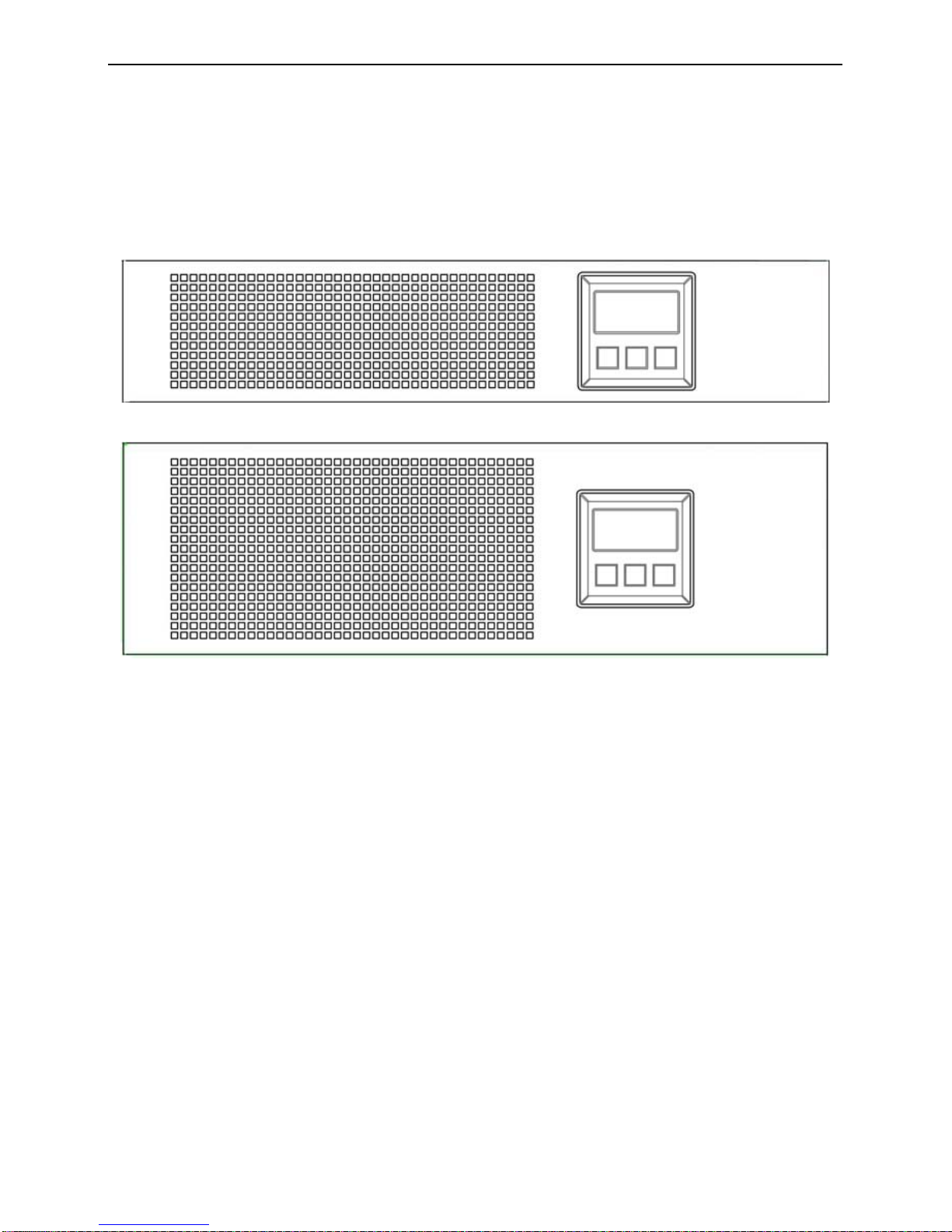
3.1 Front Panel
4K
6K
6
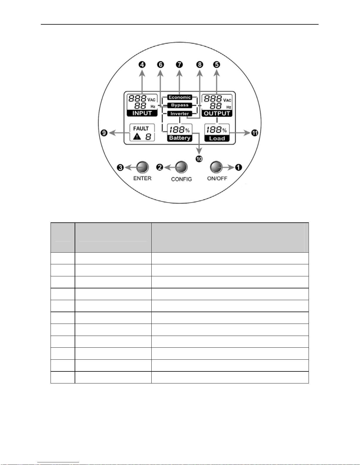
3.2 The LCD Display and Buttons Description
3.3 . ON/OFF Switch
zTo turn on the UPS, press the “ON/OFF” button for more than three seconds.
zTo turn off the UPS, press and hold the button until the UPS beep ceases.
No. Function Description
1 On/Off Switch For UPS on and off
2 Config. Switch For doing the UPS parameter configuration
3 Enter Switch To confirm the parameter setting
4 Input Information Input parameters (voltage & frequency)
5 Output Information Output parameters (voltage & frequency)
6 Bypass Indicator Operating in bypass mode
7 ECO Indicator Operating in economic mode
8 Inverter Indicator Operating in inverter mode
9 Warning Information Warning and fault indicators
10 Battery Information Battery capacity level
11 Load Information Load capacity level

7
3.4 Config Switch
Keeping this button pressed for three seconds, the LCD will enter the Configuration
Mode.
In the Configuration Mode, you can set ECO mode (i.e. economic mode) to be enabled
or disabled, Bypass mode to be enabled or disabled, and Generator input type enabled
or disabled as well. Additionally, the rated output voltage could also be changed within
220V/230V/240V.
After selecting the configuration mode, you must press the “Enter” button to confirm
the selection. Please refer to the Examples for Config Mode for more detailed
information.
Note:
1) If neither the “Config” button nor the “Enter” button pressed within 30 seconds, the
LCD system will exit from the Config Mode, and return to the original mode before the
configuration.
2) The explanation for the three modes:
a) Economic mode: The mode is for low power consumption but is recommend to
be selected only with high quality input power source.
b) Bypass mode: UPS supplies the load power from the utility directly.
c) Inverter mode (i.e. normal mode): The mode is for obtaining excellent output
quality but with higher power consumption. It is also the default setting mode.
3) Generator input type: If the mode is enabled, the UPS could accept wide range input
source, including frequency and waveform.
4) The default settings are Economic mode disabled, Bypass mode disabled, Generator
input type disabled, and the rated output voltage is at 230V.
5) Your configuration will be memorized by UPS, which means that the default setting
could be changed.
3.5 Enter Switch:
This button has three functions.
zTo confirm the selected setting in Config mode accompanying with “Config” button.
zWhen AC utility power is available and the battery is full charged, it is possible to
perform self-test function by pressing and holding the button over five seconds.
zWhen UPS is not in configuration mode, keeping this button pressed less than five
seconds can disable or enable the alarm buzzer. Each time a new alarm event is
encountered, the alarm that will sound and press this button to turn off the alarm.
Note: Unable to disable alarm buzzer as below conditions: Low Battery, Overload, Fan
Failed, Fan Fault Time Out, and Over Temperature.
Note:
If any button is pressed, the back-light LCD will be on.
In Config mode, the back-light of the LCD will be always on.
If none of the button is touched for more than one minute, the back-light will be
off automatically.
When UPS is turned on, the back-light will be active for one minute.
3.6 Input parameters (voltage & frequency)
This part gives the information of the AC utility power, including input voltage and
frequency.

8
The LCD panel indicates that the input voltage is 230V and the input frequency is
50Hz.
3.7 Output parameters (voltage & frequency)
This part gives the information of the output, including output voltage and output
frequency.
The LCD panel indicates that the output voltage is 230V and output frequency is 50Hz.
3.8 Bypass mode
The LCD symbol indicates that the UPS is in Bypass mode.
The typical display when UPS is in bypass mode:
3.9 Economic mode
The LCD symbol illuminates when UPS is in Economic mode.
The typical display when UPS is in economic mode:

9
3.10 Inverter mode
The LCD symbol illuminates when UPS is in Inverter mode (normal
mode). The typical display when UPS is in inverter mode:
3.11 Warning and fault indicator
This part shows the type of failure when the UPS fails or gives warning sound.
FAILURE
CODE STATUS DESCRIPTION
Steady Output short circuit
Flash Fan fails
Steady Fan fails and the time is out
Flash UPS is overload
Steady UPS is overload and the time is out
Flash Battery is bad or battery is disconnected
Flash Battery is overcharged
Steady Output voltage is out of range
Flash Over temperature alarm (In Bypass)
Steady Over temperature fault (Output Off)
Steady Inner circuitry fault
Note : If the symbol flashes, it means the minor problem, and the output will still be
normal.
If the symbol remains on, it means the serious problem occurs, and the output
may be cut off.
10
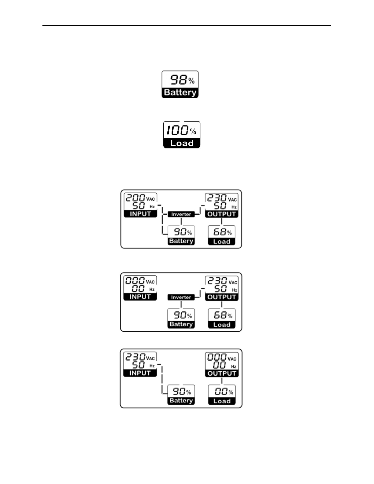
3.12 Battery capacity level
The battery capacity remains in percentage.
3.13 Load percentage indicator
This part shows the current load percentage in rated load of the UPS.
Examples for LCD display
zThe AC source is available, and the UPS is turned on (UPS in Bypass mode,
Economic mode, or Inverter mode):
zThe AC source is not present and UPS is turned on (UPS in battery mode):
zThe AC source is present but UPS doesn’t be turned on (UPS in standby mode):
11
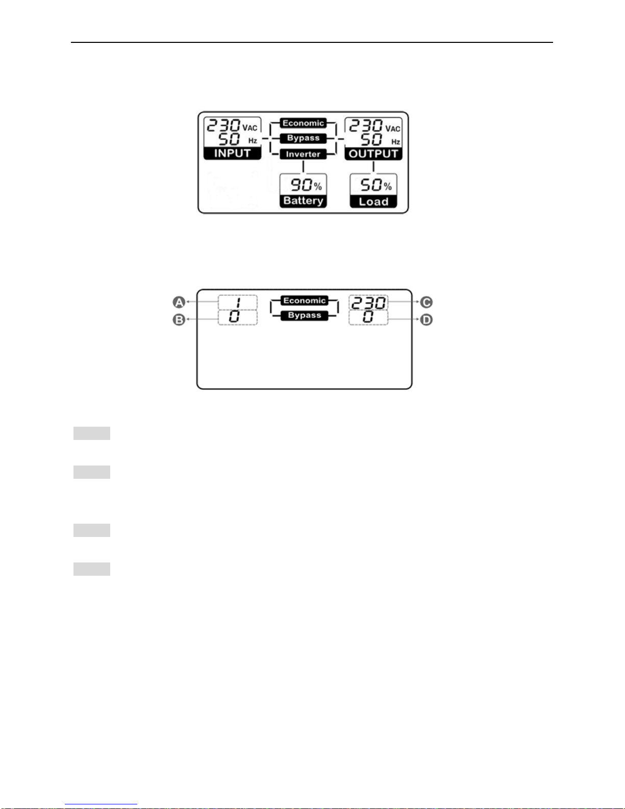
zUPS is in self test state:
Examples for Config Mode
In the Config Mode, the below information will appear in the LCD.
Explanation for four parts of the above figure:
Part A: This part is for the ECO mode enabled or disabled setting. Setting to 1 means ECO
mode is enabled. And setting to 0 means disable ECO mode. The default setting is 0.
Part B: This part is for the Bypass mode enabled or disabled setting. Setting to 1 means
the Bypass mode is enabled. Otherwise, setting to 0 means disable the Bypass mode. The
default setting is 0.
Part C: This part is for the rated output voltage setting. 220V/230V/240V are supplied for
selecting and setting. The default setting is 230V.
Part D: This part is for the Generator input type enabled or disabled setting. Setting to 1
means the Generator input type is enabled. Otherwise, setting to 0 means disable the
Generator input type. The default setting is 0.
For example, if the original settings are as follows:
ECO mode is enabled (Part A is 1 setting), Bypass mode is disabled (Part B is 0 setting),
Generator input type is disabled (Part D is 0 setting), and rated output voltage is 230V (Part
C is 230 setting).
Now, if you want to change the settings to the following:

12
ECO mode is disabled (Part A is 0 setting), Bypass mode is enabled (Part B is 1 setting),
Generator input type is enabled (Part D is 1 setting), and rated output voltage is 220V (Part
C is 220 setting).
Then, the correct steps are showed below to you to follow.
Step1: Keep the Config switch pressed for 3 seconds to enter the Config mode. The original
settings will appear in the LCD as below. And the first setting item (“1”) is blinking.
Step 2: Push the Config button to switch the option, which makes “1” switch to “0” and blink.
Step 3: Push the Enter button to confirm the option, and then the ECO mode is changed to
be disabled. Simultaneously, the second setting item (“0”) starts to blink.
Step 4: Push the Config button to switch the option, which makes “0” switch to “1” and blink.
Step 5: Push the Enter button to confirm the option, and then the Bypass mode is changed
to be enabled. Simultaneously, the third setting item (“230”) starts to blink.

13
Step 6: Push the Config button to switch the option, which makes “230” switch to “240” and
blink.
Step 7: Push the Config button again to do the second switch, which makes “240” switch to
“220” and blink.
Step 8: Push the Enter button to confirm the option, and then the rated output voltage is
changed to 220V. Simultaneously, the last setting item (“0”) starts to blink.
Step 9: Push the Config button to switch the option, which makes “0” switch to “1” and blink.
Step 10: Push the Enter button to confirm the option, and then the Generator input type is
changed to be enabled. Simultaneously, all the settings are completed.

14
Step 10: Push either the Config button or the Enter button to quit the Config mode.
Note:
1) You could press the Enter button once or the Config button twice to skip the
single setting item and keep it not changed.
2) In Config mode, if interval time between the two buttons pressed is over 30
seconds, the LCD will quit the Config mode automatically.
3) In Config mode, if On/Off button is pressed, the LCD will quit the Config mode
immediately.
Audible Alarm Introduction—
Condition Alarm Sound silence function
Warning for fan failure Continuously Sounding Can be silenced
Warning for over temperature Continuously Sounding Can be silenced
Warning for battery bad Continuously Sounding Can be silenced
Warning for battery overcharged Continuously Sounding Can be silenced
Warning for battery disconnected Sounding every second Can be silenced
Warning for overload Sounding every second Can be silenced
Warning for battery test Sounding every two seconds Can be silenced
Warning for Power Failure( Battery Mode) Sounding every four seconds Can be silenced
Warning for battery low Sounding every second Can’t be silenced
Fault for fan failure Continuously Sounding Can’t be silenced
Fault for over temperature Continuously Sounding Can’t be silenced
Fault for other failure Continuously Sounding Can be silenced
15
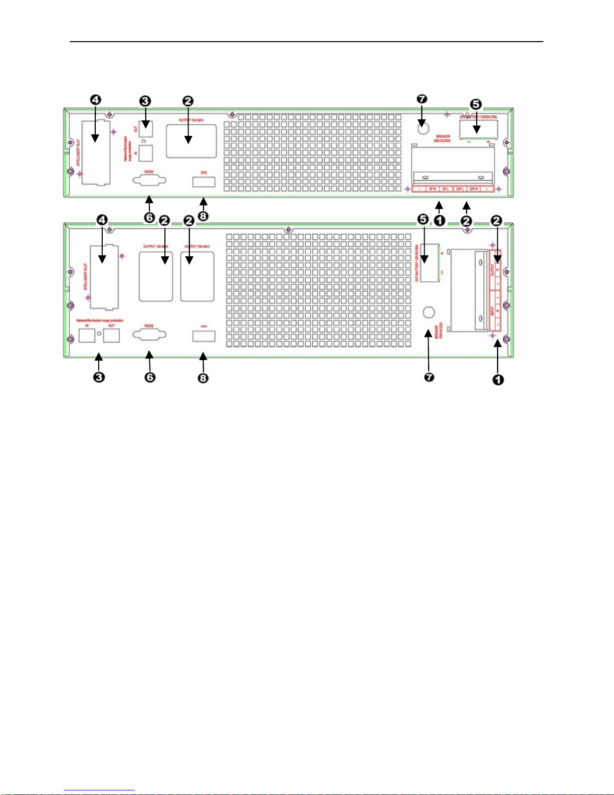
Rear Panel Description
Rear panel description table
1: I/P Terminal 5: External Battery Connector
2: O/P Terminal /Socket 6: RS232 /DRY-CONTACT
3: RJ11/RJ45 7: I/P Breaker
4: SNMP Slot 8: EPO Connector

16
4INSTALLATION
4.1 Inspecting the Equipment
Inspect the UPS upon receipt. If the UPS has been damaged during shipment,
keep the box and packing material for the carrier. Notify the carrier and dealer
immediately.
4.2 Placement
This UPS should be installed indoors with adequate airflow and free of contamination.
Locate it in a clean and indoor environment, free from moisture, flammable liquids,
and direct sunlight. Maintain a minimum clearance of 4 inches (100mm); an ambient
temperature range must be 0°C to 40°C (32°F to 104°F), and operating humidity
range must be 20% to 80% relative humidity (non-condensing).
CAUTION: The long term uses at ambient temperature in higher than 25
°
C which should
reduce battery life. In addition, place the UPS unit away from the monitor at least 20cm
to avoid interference.
4.3 Charging
This UPS is shipped from the factory with its battery fully charged; however,
some charge may be lost during shipping. The battery should be recharged
prior to use. Plug the UPS into an appropriate power supply and allow the
UPS to charge at least 4 hours.
4.4 Load Connection
Connect one load-related device to each of the power receptacles supplied at
the rear of the UPS.
4.5 Modem/Phone-line Connection
Plug incoming telephone line into the “In” socket at the back of the UPS. Use
on telephone line cable and plug one end of the telephone line cable to the
“Out” socket at the back of the UPS. Plug the other end to the modem input
socket.
4.6 DC Start Function
DC Start Function enables UPS to be started up when AC utility power is not available and
battery is full charged. Just simply press the On/Off switch to turn on the UPS
4.7 Turn On/Off
To turn on/off the UPS, you should press the on/off switch three seconds at least.
4.8 UPS Setup
All models series are designed for tower and rack purpose. They can be installed
as a 19 inch equipment rack, and also can be placed in a tower (with optional
stand) as well. Please follow the instruction for Tower Setup or Rack-Mount
Setup.
17
4.9 Tower Setup
This series can be placed in horizontally and vertically. This model is
designed in a rack itself. As a tower, it is provided with the optional UPS
stand to stabilize the UPS when the UPS is positioned in vertically. The UPS
stand must be attached to the bottom of the tower
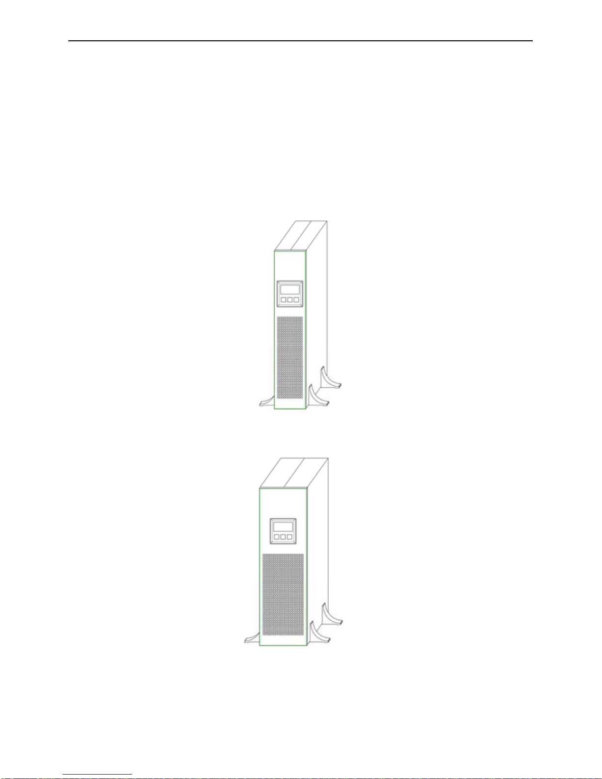
4.9.1 TOWER CONFIGURATION SETUP
This model is provided with the UPS stand necessary to stabilize the UPS when it’s
positioned in vertically. The UPS stand must be inserted to the bottom of the tower.
4KVA
6KVA

18
4.9.2 RACK-MOUNT CONFIGURATION SETUP
This UPS can be installed in 19” racks. And the UPS and external battery enclosure
need 2U /3U of valuable rack space.
4KVA/6KVA
1. Align the mounting ears with screw holes on the side of the UPS.
2. Fix the slide to the rack enclosure with screws.
3. Insert UPS into the slide assemblies and lock it in the rack enclosure.
4.9.3 LCD display cover setup
The LCD display of the this model can be rotate to adapt to rack or tower installation
Follow the below steps and charts, you can rotate the LCD display:

19
4.9.4 Emergency Power Off(EPO) setup
This UPS includes EPO port that allows power to be shut down the protected
equipment immediately and does not follow the shutdown procedure from any power
management software.
Note: When EPO switch is reset, the equipment will not return to battery power
until the UPS is manually restarted. If pressing power switch to turn off UPS
after EPO is activated, the UPS remains in Standby mode when restarted until
pressing power switch to turn on the UPS again.
Follow the procedure to install the EPO switch as below.
1. Check the UPS is turned off.
2. Remove the EPO connector from the EPO port on the rear panel of UPS
3. Connect isolated, normally-open, dry contacts (rated to handle 60Vdc
maximum, 30Vac RMS maximum, and 20mA maximum) across the EPO
device to Pin 1 and Pin 2. Use non-shield wiring, size 18-22 AWG (0.75 mm2
– 0.3 mm2).
4. Reconnect the EPO connector to the EPO port.
5. Verify that the externally-connected EPO switch is not activated to enable power
to the UPS output receptacles.
6. Plug in the UPS, then pressing power switch “ON/OFF” button to turn on the
UPS.
7. Activate the external EPO switch to test the EPO function
8. De-activate the external EPO switch and restart the UPS.
4.9.5 Net/Tel Connection
A telephone/modem or network cable can be connected to the modular RJ-45/RJ11 connectors located
on the rear of the UPS. Doing this can protect against overvoltages. A telephone extension cable is
required for this type of connection.
NOTICE: The connection is optional. The Net/Tel protection is active even when the UPS is
turned off or disconnected from mains power.
CAUTION! The device that protects against over voltage on the telephone line may not work
if it is not installed correctly. Ensure that the telephone wall cable is inserted in the connector
marked “IN” and that the cable of the unit to be protected (telephone, modem, network card,
etc.) is inserted in the connector marked “OUT”.
CAUTION! The overvoltage protection device is only for indoor use. Do not connect
telephone wires during a storm.
CAUTION! The protection device limits the effects of an over voltage but does not
guarantee overall protection.
This manual suits for next models
2
Table of contents
Other HELIOR UPS manuals


