HELIOR INVERMAX 500 User manual

USER MANUAL

General Precautions
1. Before using INVERMAX, read all instructions and cautionary markings
on :
(1) INVERMAX (2) the batteries (3) this manual
2. CAUTION --To reduce risk of injury, charge only lead-acid rechargeable
batteries. Other types of batteries may cause damage and injury.
3. Do not expose INVERMAX to rain, snow or liquids of any type.
INVERMAX is designed for indoor.
4. Do not disassemble INVERMAX. Take it to a qualified service center
when service or repair is required.
5. WARNING: Provide ventilation to outdoors from the battery
compartment. The battery enclosure should be designed to prevent
accumulation and concentration of hydrogen gas at the top of the
compartment.
6. NEVER charge a frozen battery.
7. Input/outputAC wiring must be no less than 18 AWG gauge copper wire
and rated for 75oC or higher. Battery cables must be rated for 75oC or
higher and should be no less than 10AWG gauge. The inner diameter
of the copper ring terminal which is used to connect battery cables to
INVERMAX DC terminals should be no less than 6mm.
8. Be extra cautious when working with metal tools around batteries.
Short-circuiting the batteries could cause an explosion.
9. Read the battery manufacturer’s installation and maintenance
instructions prior to operating.
Personnel Precautions
1. Have plenty of fresh water and soap nearby in case battery acid
contacts skin, clothing, or eyes.
2. Avoid touching eyes while working near batteries.
3. NEVER smoke or allow a spark or flame in vicinity of a battery.
4. Remove personal metal items such as rings, bracelets, necklaces, and
watches when working with batteries. Batteries can produce a
short-circuit current high enough to make metal melt, and could cause
severe burns.
5. If a remote or automatic generator start system is used, disable the
automatic starting circuit or disconnect the generator to prevent

accident during servicing.
Introduction
INVERMAX is a DC-to-AC inverter with auto line-to-battery transfer and
integrated charging system, serving as an extended run UPS, a
standalone power source or an automotive inverter.
INVERMAX supplies power fromAC power and DC source. WhenAC
cable is connected to a wall socket, utility power goes to connected
equipment(s) and/or charges the battery set via charging system. In UPS
mode, INVERMAX automatically convert battery energy intoAC power for
backing up the connected devices.
Features:
zAutomatic line-to-battery switchover
zSelectable Input voltage ranges
zHigh efficient DC-to-AC conversion, minimizing energy loss
zRack Tower design for flexible placement
zBuilt-in enhanced charger
zIntelligent 2-stage charger control for efficient charging and preventing
overcharge
zProvides overload protection
zAuto restart whileAC recovery
zMulti-function LED indications and buzzer alarms

Operation
Front Panel Controls and LED Indicators
Shown below are the controls and indicator lights on the front of
INVERMAX.
Figure 1 Front Panel
Power On/Off
power on/off button is shown as above. Once INVERMAX has been
properly installed and batteries are connected, press this button and
INVERMAX will turn on automatically, and works in mains mode or inverter
mode according to inputAC source’s status. When press this button again,
INVERMAX will turn off automatically.
Mains Mode LED
The green LED will blink or light steadily when power mains is normal.
Note: The green LED blinks every 2 seconds to indicate that battery
capacity is not full enough and battery is being charged by high rate.
Inverter Mode LED
The Yellow LED will light when power mains is abnormal. And unit will
work in inverter mode.
Fault LED
The red LED will light when fault occurs.
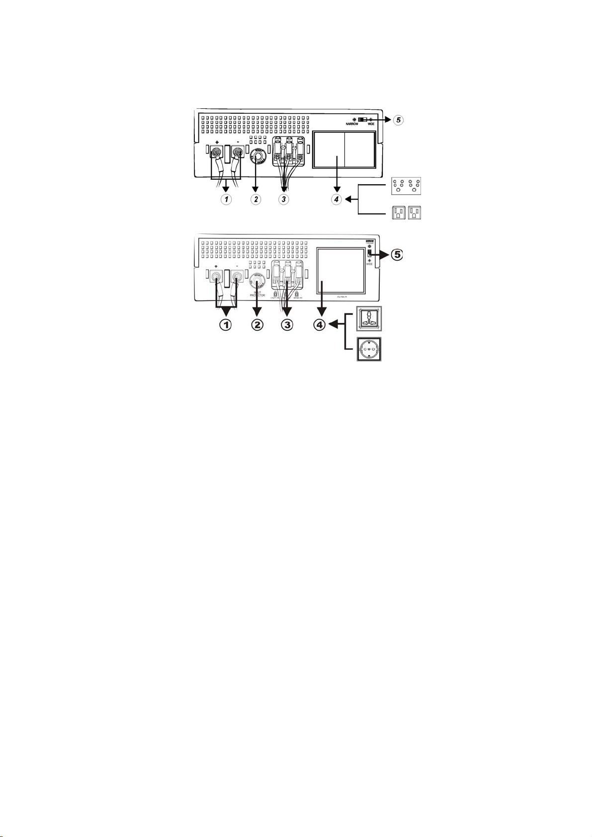
Back Panel Description
Shown below are the components on the back of INVERMAX.
Figure 2 Back Panel
1. DC Input Connector (Battery Terminal)
2. Input Breaker
3. AC Input Connector (Three-station Terminal Block)
4. Output Receptacle(s)
5. Input Voltage Range Selector : (Input voltage range is defined in
specification chapter, and output voltage is the same as input voltage in
mains mode)
A. Select ‘Narrow’ setting for general electrical appliance: If you select
this mode, the INVERMAX operating voltage in Line mode is within
170~280Vac (90~145Vac) with the same output voltage. The line
sensitivity is higher. Hence, you can connect the computer systems or
other precision home equipment when you select this mode.
B. Select ‘Wide’ setting to save energy: If you select this mode, the
INVERMAX operating voltage in Line mode will be extended within
90~280Vac (50~145Vac) with the same output voltage. The INVERMAX
is with the lower line sensitivity. Moreover, there will be taking a long
transfer time when the INVERMAX transfer from Normal mode to
Battery mode during power failure. Hence, you can connect the home
equipments, such as light bulb, fan, fluorescent tube, or TV when you
select this mode.
Caution!! If you select the ‘Wide’ mode and connect the computer to
the output of INVERMAX, the computer may reboot if the input voltage
is too low to be accepted. In addition, the long transfer time will happen
when power failure makes the computer reboot.
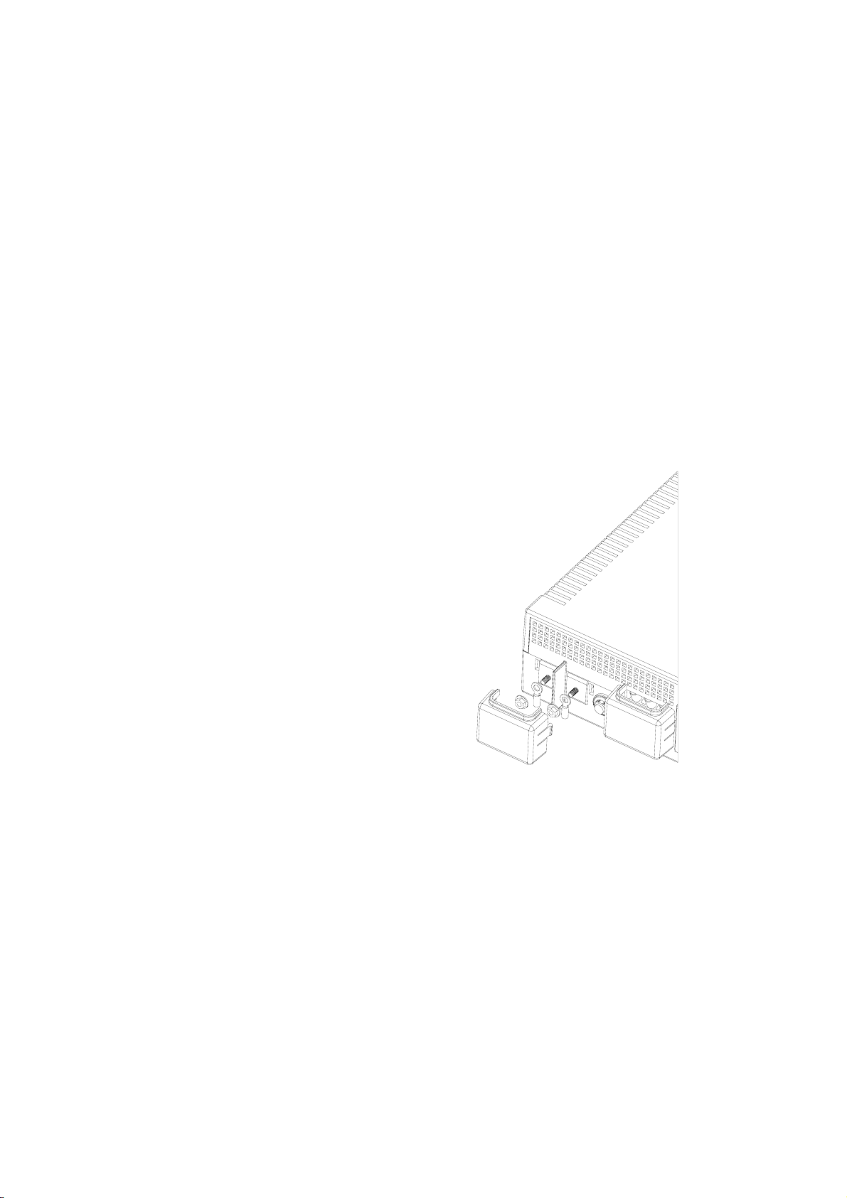
Battery Connection
Step 1- Pinch the bottom of DC input cover and Open it. See Figure 4.
Step 2- Following battery polarity guide located near battery
terminal! Place the battery cable ring terminal over
INVERMAX’s battery terminal. Tighten the M5 nut. Do
not place anything between the flat part of battery
terminal and the battery cable ring terminal, or
overheating may occur.
Caution! DO NOT place anything between
battery cable ring terminals and battery
terminals. The terminal stud is not designed
to carry current.Apply Anti-oxidant paste to
terminals after terminals have been torqued.
Figure 4 Battery Cable Connection to Inverex

Step 3- Connect battery cables to your batteries
zSingle battery connection: When using a single battery, its voltage must
be equal to the voltage of INVERMAX Nominal Input Voltage
(Apply to INVERMAX 500/1000)
zFor the user operation safety, we strongly recommend that you should
isolate the battery terminals before you start to operate the unit. Please
refer to below instruction for further information. If you parallel more
batteries to extend the backup time, please make sure that you already
use tapes to isolate the rest battery terminals before you start to
operate the unit.

zSeries battery connection: When using multiple batteries in series, all
batteries must be equal in voltage and amp hour capacity, and the sum
of their voltages must be equal to the voltage of INVERMAX Nominal
Input Voltage (Apply to INVERMAX 1500/2000)
zParallel battery connection: When using multiple batteries in parallel,
each battery’s voltage must be equal to the voltage of INVERMAX
Nominal Input Voltage (Apply to INVERMAX 500/1000 extend the
backup time)

AC Connection
Before having AC connection, match the power requirements of connected
devices with the power output of INVERMAX to avoid overload. Consult
a qualified electrician, and follow local code for the proper wire sizes,
connectors and conduit requirements.
Step 1- A three-station terminal block is provided to makeAC input
connections. Remove the cover plate.
Caution!! Be sure that AC source is disconnected before attempting to
connect AC to INVERMAX.
Step 2- Connect the hot wire (black/brown)
of AC input cable to the HOT IN terminal.
Step 3- Connect the neutral wire (white/blue)
of AC input cable to the NEU IN terminal
Step 4- Connect the ground wire
(green) of AC input cable
to the GND IN terminal
Step 5- Tighten screws to affix wires
in terminal block.
Step 6- Cover up theAC Input by the
plastic cover.
Step 7- Simply plug your equipment(s)
into the output receptacle(s).
Step 8- Turn on INVERMAX when you are
using connected equipment(s).
Figure 5 AC Input Connections

Troubleshooting
Problem Possible Cause Remedy
1. Battery Weak
1. Re-charge battery
cable and DC input
connection.
2. Battery defect
2
. Battery replacement.
No LED display
3. Power switch is not
pressed
3
. Press and hold power
switch.
1. AC Input is missing 1. Check AC input
connection.
Mains normal but
works in inverter
mode 2. Input protector is
effective
2
. Reset the input
protector.
Alarm buzzer beeps
continuously 1. Overload
1. Verify that the load
matches the
capability specified in
the specs.
1.Overload
1. Remove some
non-critical load.
Back up time is
shorten 2.Battery voltage is too
low.
2
. Charge battery for 8
hours or more.
If any abnormal situations occur that are not listed above, please call
service people immediately.

Specification
MODEL INVERMAX 500 INVERMAX 1000 INVERMAX 1500 INVERMAX 2000
CAPACITY VA/W 500VA/300W 1000VA/600W 1500VA/900W 2000VA/1200W
Nominal Voltage 110/120VAC or 220/230/240VAC
90-145VAC or 170-280VAC (Narrow Range)
INPUT
Voltage Range 50-145VAC or 90-280VAC (Wide Range)
OUTPUT Voltage 120VAC or 230VAC
Voltage Regulation(Batt. Mode) +10% / -18%
Frequency 50Hz or 60Hz
Frequency Regulation (Batt. Mode) +/-0.1 Hz
Output Waveform Modified Sine-wave
Charger Current 8 Amp +/- 1Amp 10Amp +/- 1Amp 10 Amp +/- 1Amp 10 Amp +/- 1Amp
DC Voltage 12V +/- 0.2V 12V +/- 0.2V 24V +/- 0.4V 24V +/- 0.4V
BATTERY & CHARGER
Overcharge Protection 14.5V +/- 0.3V charger stops and
fault 29V +/- 0.6V charger stops and fault
TRANSFER TIME Typical 8ms Typical
A
C to AC >95%
EFFICIENCY
DC to AC >80%
A
C Mode Green lighting
Battery Mode Yellow lighting
Battery Charging Mode Green flashing every 2 seconds
Overload Red flashing every 0.5 second
INDICATOR
Fault Red lighting
Low Battery at Battery Mode Sounding every 2 seconds
Overload Sounding every 0.5 second
AUDIBLE ALARM
Fault Continously sounding
PROTECTION Full Protection Discharge, overcharge, and overload protection
Dimension (DxWxH) mm 224 X 255 X 80
PHYSICAL
Net Weight (kgs) 2.0 2.3 2.5
Operating Environment 0- 40°C, 0-90 % relative humidity (non-condensing)
ENVIRONMENT
Noise Level Less than 55dB
* Product specifications are subject to change without further notice
This manual suits for next models
3
Table of contents
Other HELIOR UPS manuals


