Helios CURIO User manual

BUOYANCY COMPENSATOR
CURIO
USER’S MANUAL
사용자 메뉴얼
使用 说明书

2| G E M M A T E C H N I C A L
© 2015 Gemma Technical Co., Ltd. All rights reserved.
This document is copyright and contains confidential information that is the property of Gemma Technical
Company Limited. Any reproduction, retransmission, republication, stored in a retrieval system, translated
into any language in any form by any means, or other use of all or part of this document is expressly
prohibited, without prior written consent from Gemma Technical Co., Ltd.
Helios is a registered trademark of Gemma Technical Co., Ltd.
본매뉴얼은 대한민국 저작권법에 의해 보호를 받는 저작물이므로 이를 무단 이용하는 경우 저작권법
등에 따라 법적 책임을 질수있습니다. 무단전재와 무단 복제를 엄금합니다.
本说明书受著作法律保护,擅自使用会依法追究法律责任,严禁擅自转载和复制。
Legal Disclaimer
Gemma Technical Co., Ltd. aims to make the information on this document as accurate as possible. Gemma
Technical Co., Ltd. does not make any claims, promises or guarantees about the accuracy, completeness, or
adequacy of the contents of this document, and expressly disclaims liability for errors and omissions in its
contents. Information in this document is for general information purposes only. Gemma Technical Co., Ltd.
disclaims and excludes any liability for incidental or consequential damages.
본매뉴얼에 포함된 내용은 일반적인 안내를 위한 것입니다. 제공되는 모든 내용은 완성도, 정확도 또는
이정보를 사용하여 발생하는 결과, 우발적 손해 또는 결과적 손해에 대하여 (주) 젬마테크니칼은 어떠한
보증도 책임도 제공하지 못합니다.
本说明书所包含的内容是为了说明一般情况,所提供的内容完成度,精准度,以及根据这些信息操作时产生
的结果及偶发性损害,我公司不负担任何责任。

3| H E L I O S
PREFACE
머리말 绪论
HELIOS Backplate & Wing (BP&W) System Buoyancy Compensators are designed to provide
sufficient buoyancy to float at the surface and help you maintain neutral buoyancy in a face-
down horizontal position underwater. HELIOS Backplate & Wing System Buoyancy
Compensators are designed to provide comfort in recreational scuba diving. Our BCs have
been constructed from high quality rugged materials for best performance and reliability.
헬리오스 백플레이트 + 윙부력조절장치는 다이버가 수중에서는 균형감 있는 자세로 중성
부력을 유지하고, 수면에서는 충분한 부력으로 떠있을 수있도록 도움을 드리고자 설계된
제품입니다. 간결하면서 안정감을 더해주는 디자인으로 레크레이션 다이빙을 더욱
편안하게 즐길 수있습니다. 최고의 성능과 신뢰성을 위해 헬리오스 백플레이트+윙
부력조절장치는 내구성이 뛰어나고 강한 고품질 재질로 견고하게 만들어 졌습니다
HELIOS 浮力调整器能使潜水员在水中保持平衡的中性浮力的姿势,也可帮助潜水员在水面上浮
起。简单及安全的设计使您能更好的享受休闲潜水带来的快乐。为了最高的性能和信赖性,
HELIOS 浮力调整器使用高强度的材料制成,坚固耐用。
PLEASE CAREFULLY READ ALL CONTENTS OF THIS USER MANUAL BEFORE USING
THIS BUOYANCY COMPENSATOR.
제품을 사용하기 전에 메뉴얼을 읽고 올바르게 사용해 주십시오
在使用本产品前,请仔细阅读本说明书,并正确使用。
DO NOT USE THIS BUOYANCY COMPENSATOR UNLESS YOU ARE A CERTIFIED
SCUBA DIVER AND HAVE SUCCESSFULLY COMPLETED TRAINING COURSES BY
RECOGNIZED TRAINING & CERTIFICATION AGENCIES.
전문 스쿠버 다이빙 교육기관으로부터 올바른 교육과정을 이수한 자격증 취득자만
헬리오스 백플레이트 + 윙부력장치 를사용하실 수있습니다
只有从专门的潜水教育机构正确的学习并取得资格证的人才能使用 HELIOS 浮力调整器。
4| G E M M A T E C H N I C A L
For further questions regarding HELIOS Buoyancy Compensators and other HELIOS products,
please contact us below:
헬리오스 백플레이트 + 윙부력장치 또는 기타제품관련 추가 문의사항은 아래로 연락
주시기 바랍니다
关于 HELIOS 浮力调整器货其他产品相关的问题,请与以下地址联系。
International
GEMMA TECHNICAL CO., LTD
Helios Scuba Division
1585, Seohaean-Ro, Siheung-si
Gyeonggi-Do, Korea 14902
Tel: +82 (0)31 315-5006
inquiry@gemmatec.co.kr
한국어
(주)젬마테크니칼
헬리오스 스쿠버 사업부
경기도 시흥시 서해안로 1585
대한민국 (우편번호: 14902)
전화: +82 (0)31 315-5006
inquiry@gemmatec.co.kr
中文
HELIOS 潜水设备中国部
山东省烟台市芝罘区黄务街道办事处东里村基督大街 99 号
Tel: +86 (0)535-6979899
www.helios-scuba.com.cn

5| H E L I O S
TABLE OF CONTENTS 목차 目录
Important Safety Instructions, Warnings, and Precautions
6
CURIO Wing and BCD System Configuration
8
A1 Harness System Assembly Guide
10
Crotch Strap Mounting Guide
16
CURIO Backplate & Wing Assembly Guide
17
How to Use the Power Inflator
22
Care & Maintenance
24
Frequently Asked Questions
25
Warranty
26
Service & Maintenance Records
71
Product Registration
72
Product Registration Form
75
주요 안전 지침, 경고 및주의사항
28
큐리오 A1 시스템 백플레이트 + 윙구성도
30
A1 하네스와 백플레이트 설치 가이드
32
크로치 스트랩 설치 가이드
38
큐리오 백플레이트 + 윙시스템 조립 가이드
39
파워 인플레이터 사용 방법
44
제품의 유지 관리
46
자주 묻는 질문
47
제품 품질보증서
48
유지 보수 기록
71
제품 등록
72
제품 등록서
75
主要安全指南及注意事项
50
CURIO A1 装备构成介绍
52
CURIO A1 织带安装指导
54
胯下带安装织带
60
CURIO A1 装备组装指导
61
POWER INFLATOR 使用方法
66
产品的维护管理
68
常见问题及解答
69
产品品质保证书
70
保养及维修记录
71
产品登录
72
产品登录表
75
6| G E M M A T E C H N I C A L
IMPORTANT SAFETY INSTRUCTIONS, WARNINGS, & PRECAUTIONS
READ THIS OWNER’S MANUAL COMPLETELY AND UNDERSTAND ENTIRELY PRIOR TO USING THIS
BUOYANCY COMPENSATOR (BC).
THIS MANUAL MAY PROVIDE BASIC GUIDELINES FOR BUOYANCY CONTROL TECHNIQUES, BUT IS
NOT A SUBSTITUTE FOR PROPER TRAINING FROM A CERTIFIED PROFESSIONAL DIVING
INSTRUCTOR.
IMPROPER USE AND/OR MISUSE OF THIS BOUYANCY COMPENSATOR (BC) MAY CAUSE SERIOUS
INJURY OR DEATH
DO NOT USE THIS BUOYANCY COMPENSATOR (BC) IF YOU HAVE NOT BEEN PROPERLY TRAINED
AND HAVE NOT SUCCESSFULLY COMPLETED A SCUBA DIVING COURSE BY A RECOGNIZED
TRAINING & CERTIFICATION AGENCY. USE OF THIS BC BY UNTRAINED & UNCERTIFIED PERSON(S)
IS EXTREMELY DANGEROUS AND CAN CAUSE SERIOUS INJURY OR DEATH
THIS BUOYANCY COMPENSATOR (BC) IS NOT A LIFE JACKET. INAN EMERGENCY, THIS BUOYANCY
COMPENSATOR MAY NOT PROVIDE A FACE UP POSITION OR FLOATATION OF THE WEARERAT
THE SURFACE IN ALL CONDITIONS. IF THE WEARER BECOMES UNCONSCIOUS IN THE WATER,
WITHOUTA BUDDY PRESENT TO PROVIDE IMMEDIATE ASSISTANCE, THE WEARER MAY SUFFER
SERIOUS INJURY OR DEATH.
DO NOT BREATHE FROM OR INHALE FROM THE ORAL INFLATION MOUTHPIECE OR AND/OR
BUOYANCY COMPENSATOR (BC). THE INNER BLADDER OR BC MAY CONTAIN HARMFUL GASES,
RESIDUE, LIQUID, OR CONTAMINANTS WHICH COULD CAUSE SERIOUS INJURY, SUFFOCATION,
OR DEATH.
ALWAYS PERFORM PRE-DIVE INSPECTIONS OF THIS BUOYANCY COMPENSATOR (BC) DESCRIBED
IN THIS MANUAL TO ENSURE: ALL BOLTS & ATTACHMENTS ARE SECURELY CONNECTED, ALL
COMPONENTS ARE FUNCTIONING PROPERLY, AND THERE ARE NOT SIGNS OF LEAKS OR
DAMAGES.
DO NOT USE THIS BUOYANCY COMPENSATOR (BC) IF YOU CAN HEAR ANY LEAKAGE, OR IF THE
BLADDER BEGINS DEFLATE WITHIN 5 TO 10 MINUTES.
WARNING
!
WARNING
!
WARNING
!
WARNING
!
WARNING
!
WARNING
!
WARNING
!
WARNING
!
7| H E L I O S
TOTAL WEIGHT CARRIED BY THE WEARER OF THIS BUOYANCY COMPENSATOR MUST BE
PROPERLY CALCULATED AND TESTED FOR OPTIMUM BUOYANCY PRIOR TO DIVING
UNDERWATER. FAILURE TO PROPERLY WEIGHT YOURSELF MAY CREATE HAZARDOUS
CONDITIONS WHICH COULD RESULT IN SERIOUS INJURY OR DEATH
ALWAYS WET THE TANK/CYLINDER ADAPTER STRAPS (HARNESS WEBBING) PRIOR TO
CONNECTING & SECURING THE TANK/ CYLINDER TO THE BC (ADAPTER). THE TANK/CYLINDER
ADAPTER STRAPS (HARNESS WEBBING) MAY STRETCH & LOOSEN; WHICH MAY CAUSE THE TANK/
CYLINDER STRAPS TO FALL OUT. VERIFY THE TENSION OF THE CYLINDER CONNECTION PRIOR
TO EVERY DIVE.
THIS BUOYANCY COMPENSATOR IS DESIGNED FOR SINGLE TANK / CYLINDER ATTACHMENT ONLY
AND NOT INTENDED TO BE USED WITH TWIN TANKS/CYLINDERS. THIS BUOYANCY COMPENSATOR
/ WING COMES IN LIFT CAPACITY OF 27lbs (12kg)
DO NOT OVERINFLATE THIS BUOYANCY COMPENSATOR (BC). IMMEDIATELY BEGIN
VENT/RELEASE AIR FROM THIS BC USING THE DEFLATE BUTTON ON THE POWER INFLATOR OR
PULLING THE CORD OF THE DUMP (OVERPRESSURE) VALVE. CONTINUE VENT / RELEASE AIR TO
SLOW YOUR ASCENT RATE. AN UNCONTROLLED RAPID ASCENT MAY CAUSE DECOMPRESSION
SICKNESS OR ARTERIAL GAS EMBOLISM WHICH MAY LEAD TO SERIOUS INJURY OR DEATH
TEMPERATURE LIMITATIONS MUST BE ADHERED: THIS BUOYANCY COMPENSATOR SHOULD BE
USED IN TEMPERATURES NO LOWER THAN 1 DEGREE CELSIUS (40°F) AND NOT HIGHER THAN 34
DEGREES CELSIUS (104°F)
IF YOUARE NOT A FACTORY TRAINED, HELIOS AUTHORIZED TECHNICIAN, DO NOT ATTEMPT TO
PERFORM REPAIRS, NON PRESCRIBED DISASSEMBLIES, LUBRICATIONS, OR SERVICING TO THIS
BUOYANCY COMPENSATOR (BC). UNAUTHORIZED SERVICE(S) TO THIS BC WILL VOID & NULLALL
AND ANY WARRANTIES.
DO NOT RELY SOLELY ON THE POWER INFLATOR TO INFLATE THIS BUOYANCY COMPENSATOR.
PRACTICE THE TECHNIQUE OF ORALLY INFLATING YOUR BC.
FAMILIARIZE YOURSELF WITH THIS BC, ITS ADJUSTMENTS, AND ITS FEATURES IN A CONTROLLED
ENVIRONMENT SUCH ASA SWIMMING POOL PRIOR TO USING THIS BC IN DEEPER WATERS
WARNING
!
WARNING
!
WARNING
!
WARNING
!
WARNING
!
WARNING
!
WARNING
!
WARNING
!
8| G E M M A T E C H N I C A L
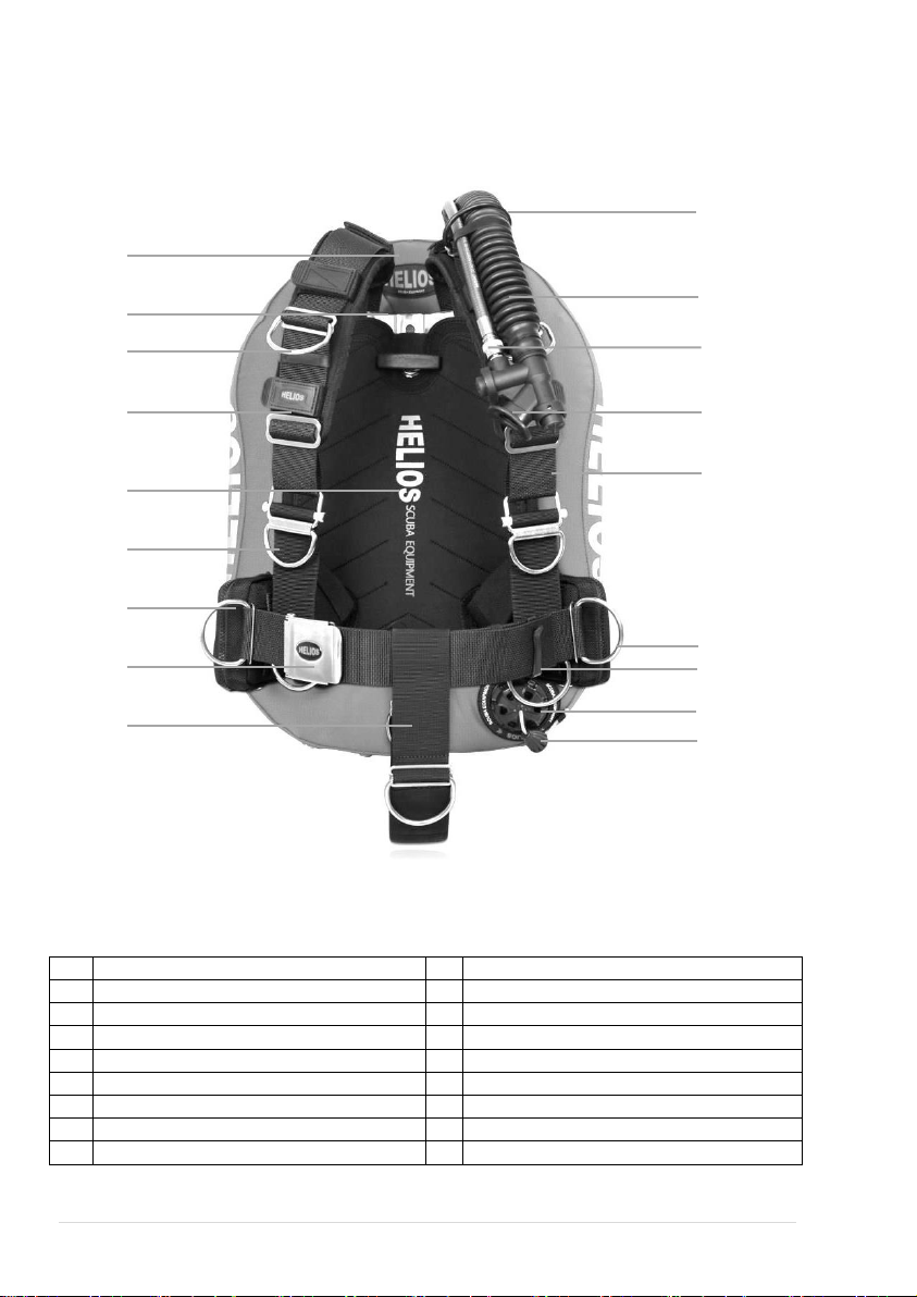
CURIO WING & BCD SYSTEM CONFIGURATION
FRONT
A
HELIOS CURIO Wing Outer Shell
J
Rubber round ring
B
Hard coat Aluminum / SS Back Plate
K
16”EPDM Corrugated Tech Hose
C
2” S/S Bent D-Ring
L
LP BC Inflator hose with QD
D
Shoulder Pads
M
K Tech Power Inflator
E
Back Plate Pad Pouch
N
2” Webbing Harness for Shoulder
F
HELIOS A1 QP
O
2” S/S D-Ring
G
5lb [2kg] Weight Pocket (Zippered) (Optional)
P
Plastic Webbing Clip
H
S/S Waist buckle
Q
Over Pressure Valve [Exhaust Valve]
I
Crotch Strap
R
Pull Cord
A
B
C
E
F
G
H
I
J
K
L
M
N
O
P
Q
R
D
[PHOTO: CURIO A1 QP BC System]

9| H E L I O S
S
Inflator Elbow
T
Inflator Elbow housing
U
Stainless Steel tank adapter
V
SS Cam buckle and tank straps
(For use with SS tank adapter only)
[Photo: CURIO BC System]
[Photo: CURIO Wing & X1 DIR Harness Assembly]

10 | G E M M A T E C H N I C A L
A1 HARNESS SYSTEM ASSEMBLY GUIDE
HELIOS A1 harness is a front adjustable harness system consisting of 3 main webbings and a crotch strap.
1
Shoulder webbing: 2” nylon webbing with center grommet
150cm
2
Left waist webbing: 2” nylon with integrated D-ring handle
135cm
3
Right waist webbing: 2” nylon with integrated D-ring handle
110cm or 135cm
4
Crotch strap with integrated D-ring
110cm
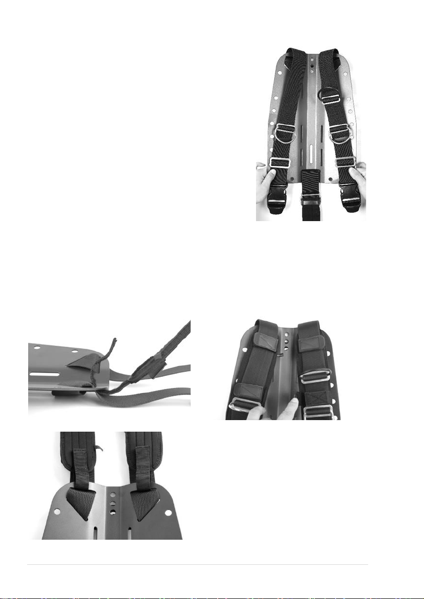
A1 harness is threaded through a total of 9 slots on the back plate which includes 1 slot to install the 2”
crotch strap
Top
This side UP / FRONT
Insert the shoulder webbing into slot R1 front of the back plate
Flip the backplate to the back side
Pull the webbing and insert to slot L1 from back side of backplate
Flip the backplate to its front side. Pull the webbing until centered by aligning the center grommet to
the third hole from top of the backplate.
Insert the left end of the webbing to slot L2 and right end of the webbing to slot R2
Shoulder webbing both right and left will come over top edge of backplate
SLOT R2
SLOT R1
SLOT L2
SLOT L1
SLOT L3
SLOT L4
SLOT R3
SLOT R4
SLOT C1

11 | H E L I O S
A1 WEBBING HARDWARE
Hardware
Usage
Qty
Rubber Round Ring
Inflator hose guide
1
Webbing rubber band
Securing excess webbing
4
2” S/S Bent D-rings
2
2” S/S Straight/ standard D-rings
Not including integrated D-rings
3
2” tri-glides
8
2” tri-glides 3 slots (chest strap tri-glide)
Each end of the chest strap pre-installed
2
Plastic webbing clip
Used for excess belt webbing
1
Helios A1 QP
(Side Release Webbing buckle is optional)
Front adjustment
2
S/S Waist buckle
1
On the left shoulder webbing insert/loop a tri-glide with the
round Rubber ring. Thread the webbing in the tri-glide as per
illustration. This rubber round ring is used to guide the inflator
corrugated hose.
Insert/ loop a tri-glide and a bent D-ring on both of the left and
right shoulder webbing. Make sure the curve of the bent D-ring
is pointing outward.
These bent D-rings on the upper-chest should be positioned so
you may comfortable attach and detach items using the same
side hand. (While folding your arms parallel to the ground your
thumb should fold around the center of the bent D-ring when
properly positioned)
Insert a webbing rubber band (snoopy loop) to the webbing
Thread the Wide Tri-glide to the left and right shoulder webbing.
Loop each end of shoulder webbing through the top slot of the
Stainless steel A1 QP (Quick Pull) buckle or thermoplastic SR
(side release) webbing buckle. (See below illustration of the
quick pull)
Thread the remaining webbing back into the wide tri-glide
Allow sufficient space between the wide Tri-glide and the A1
QP (Quick Pull) buckle or thermoplastic SR (side release)
webbing buckle to install the shoulder pad Velcro tabs
Finally insert the excess webbing in the rubber band
A1 Quick
Pull Top slot
A1 Quick Pull
Bottom slot
SR Buckle
Top slot
SR Buckle
Bottom slots for
waist webbing
12 | G E M M A T E C H N I C A L
The image on the right shows a completed shoulder webbing
installation without shoulder pads
Allow sufficient room between the stainless steel hardware to
install the shoulder pad Velcro tabs
The position of the Chest Strap tri-glides and the Quick Pull
webbing buckles must be parallel on both the left and right
shoulder webbings.
Lengths of the left and right shoulder webbings must be even
Adjust the lengths of the shoulder webbings for a perfect fit
INSTALLING THE SHOULDER PADS
Open the adjustable Velcro straps located on the top end of the shoulder pad
Insert the Velcro straps facing up to slots R2 and L2 the close the Velcro to the desired lengths
Shoulder pads are always positioned between your shoulder and the shoulder webbing. The webbing
is on the outside of the pad
Open the Velcro tabs located on each of the pads. Line up the shoulder pads with the webbing
Adjust the length of the shoulder pad or the position of the tri-glides so that there is room between the
tabs and the tri-glides
Note: Number of and design of Velcro straps and tabs may vary on different Shoulder pads
CAUTION: The tri-glides may damage the tabs on the shoulder pads when improperly installed

13 | H E L I O S
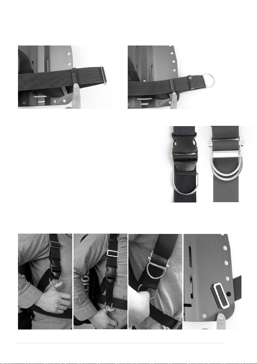
INSTALLING THE LEFT & RIGHT WAIST WEBBING
The right waist webbing is shorter than the left
waist webbing
Hold the belt webbing by the D-ring end so
that the seam faces down. Insert the end of
the waist webbing (opposite side of the
integrated D-ring) in to the A1 QP or SR
webbing buckle. Start from the bottom then
loop over the center moving bar of the A1 QP
or SR pull webbing buckle
Pull the waist webbing all the way down until
the D-ring stops at the A1 QP or SR webbing
buckle
An elastic nylon band is installed on the cross
section seam where the nylon and polyester
webbing connects
Insert the right waist webbing into SLOT L4 from
the front of the back plate
Note: the shoulder webbing and the belt
webbing should face forward when inserting the
waist webbing into SLOT L4
Pull the webbing from the back until the cross
section is approximately 10cm from SLOT L4.
Adjust lengths according to your fit
Flip the back plate to the back side
Insert a tri-glide then insert the waist webbing
into SLOT L3.
The “Sliding Glider”can be only installed on the
waist webbing slots for X1 DIR Harness
(continuous webbing)
Turn the backplate to the front and pull the webbing fully
Install the weight pocket (diver preference)
Thread a tri-glide and D-ring. This D-ring should be located on the hip or directly above.
Note: D-rings on hip are used to attach secondary regulator (octopus) hose clips, pressure gauge, or
other tools during your dive
14 | G E M M A T E C H N I C A L
Repeat the above steps for the left waist webbing but using SLOT R4 then R3 on the back plate
Insert the plastic webbing clip to the left waist webbing
Insert a webbing rubber band which will be used later to secure excess webbing
FITTING YOUR CURIO HARNESS
Before you install the waist buckle, adjust the lengths of the
shoulder webbings and waist webbings for a comfortable fit
A good fit is a comfortable and safe fit
First try on the A1 harness system which you have installed so
far
The A1 QP (Quick Pull) buckle or thermoplastic SR (side
release) webbing buckle should be located either on the chest
or under the chest most comfortable for the individual diver.
Adjust the shoulder webbing accordingly
Pull down the integrated D-rings looped around the A1 QP or
SR webbing buckles. See Illustration
When fit snug the D-rings should drop approximately 10cm. If
longer or too short, loosen the tri-glides on the back of the
backplate and adjust the length.
Once the fit of the harness has been adjusted, extend your
right hand over your shoulder and try reaching the top edge of
the backplate. If your fingers touch the backplate, you have adjusted the harness properly.
Note: DO NOT install the “sliding glider”on a A1 QP or SR webbing buckle harness assembly. Side realease
webbing buckles are optional (sold separately)
15 | H E L I O S
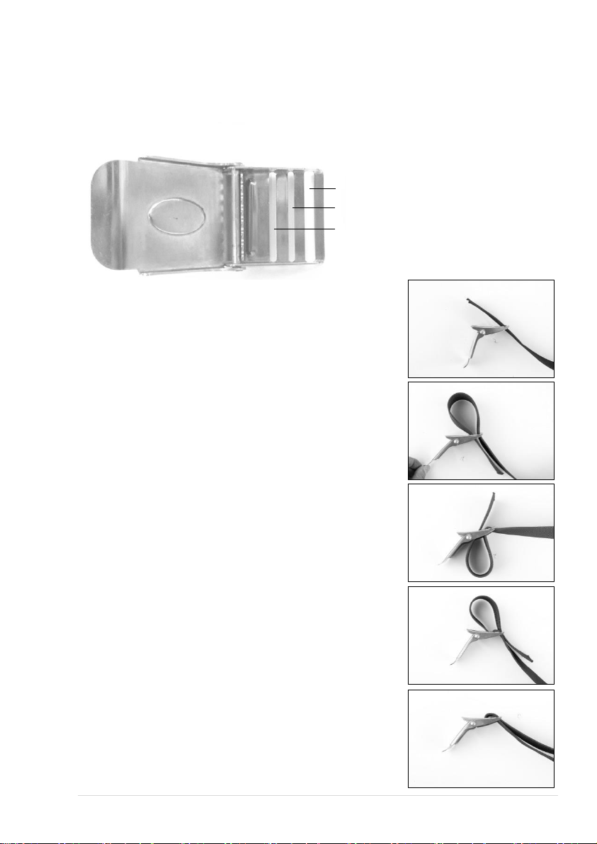
ATTACHING THE WAIST BUCKLE
You are now ready to install the waist buckle
The waist buckle will installed on the left waist webbing and will be positioned on the right not the
center. This is to prevent the crotch strap from accidentally opening the waist buckle.
Insert the left waist webbing from the front opening into SLOT A
of the waist buckle
From the back side of the buckle, insert webbing into SLOT B
From the front, insert webbing into SLOT C
From the back, insert webbing into SLOT A
Pull the webbing fully and secure excess webbing in to the
rubber band
SLOT A
SLOT B
SLOT C

16 | G E M M A T E C H N I C A L
CROTCH STRAP MOUNTING GUIDE
The front and top side of the crotch strap has an integrated (sewn in) D-ring pointing outward and looped
webbing. The waist webbing belt will run through the looped webbing of the crotch strap.
Insert a webbing rubber band (snoopy loop) into the back end of the crotch strap
Thread a tri-glide and D-ring pointing outward (when worn)
Insert the crotch strap webbing to SLOT C starting from the back of the backplate
Pull and thread back into the tri-glide. See illustration
The back D-ring should be positioned approximately a width of 4 fingers. See illustration
Adjust the length of the crotch strap for a comfortable fit.
Secure excess strap webbing into the rubber band (and through the crotch strap pad)
Cut off excess strap webbing when too long

17 | H E L I O S
CURIO BACKPLATE & WING ASSEMBLY GUIDE
Mounting Hardware
NO.
ITEM
MATERIAL
QTY
PICTURE
1
30mm (M8) or 1-1/4”
Carriage bolt with
slotted/ non-slotted
round head, flat
washer, lock washer,
and wing nut set
Square width < 8.1mm
(Use metric thread for T
handle mount)
Stainless
Steel
2
2
Single Tank Adapter
(STA)
Stainless
Steel
1
3
(Optional)
30mm metric thread
Carriage bolt with
slotted or non-slotted
round head, 16mm flat
washer, and T handle
set.
(24mm flat washer &
15mm lock washer re-
used)
Stainless
Steel
Thermoplastic
1
CURIO WINGS MUST BE ATTACHED TO THE BACKPLATE USING TWO BOLTS & NUTS TIGHTENED
SECURELY. FAILURE TO USE TWO BOLTS & NUTS AS INSTRUCTED IN THIS MANUAL MAY LEAD TO
PRODUCT DAMAGE AND COULD LEAD TO SERIOUS INJURY
WARNING
!
18 | G E M M A T E C H N I C A L
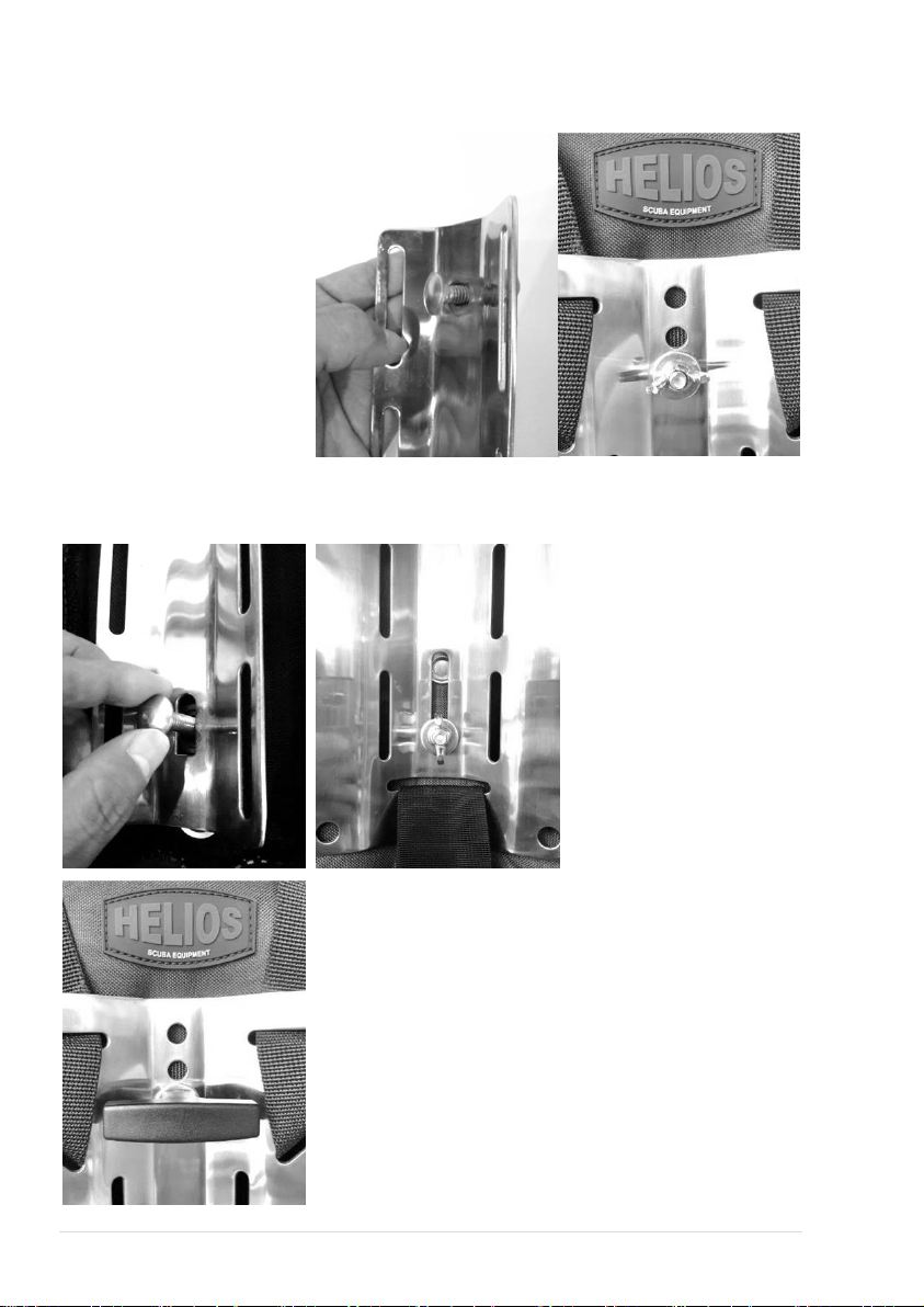
SINGLE TANK ADAPTER (STA), WING, BACKPLATE ASSEMBLY
Insert the 30mm or 1-1/4”
carriage bolt through the
SS tank adapter (STA) then
to the back of the CURIO
Wing in the top grommet/
eyelet located in the spine
of the wing
Flip the wing to the front.
Make sure you are holding
the carriage bolt pushed in
the top grommet (You may
insert a large flat washer to
prevent damage to the
grommets)
Align the third hole from top
of the Backplate center
spine together with carriage
bolt threaded end
CAUTION: Make sure the
bolt threaded end passes through the grommet on the webbing
Push the carriage bolt threaded end out from the backplate third hole then insert a 24mm flat washer
first, then a lock washer. Tighten the wing nut firmly
Repeat the same steps for the
bottom bolt assembly. Tighten
securely.
(Optional) For installation of the T-handle, use only a metric sized
30mm (M8) bolt. Repeat the same steps as above. Before fastening
the T-handle insert a (16mm) flat washer to prevent the lock washer
from damaging the T-handle. Tighten securely.

19 | H E L I O S
THREADING THE TANK/ CYLINDER STRAPS
(Standard) When the Curio wing & backplate assembly is installed
with a single tank adapter (STA):
Place the tank strap flat so that the HELIOS logo is facing up.
The Velcro should be facing down on the left and the CAM
buckle should be to your right
Thread the Velcro end of the tank strap through the top slots of
the single tank adapter (STA)
Slide in the rubber friction pad on the tanks strap (Velcro end).
The rubber friction pad grooved surface is on the opposite side
of the Velcro
Repeat above steps to install the second tank strap to the
bottom slots of the single tank adapter.
(Optional) When the wing & backplate assembly is installed without a single tank adapter (STA) where the
wing is directly mounted to the backplate using nuts & bolts:
Place the tank strap flat so that the HELIOS logo is facing up.
The Velcro should be facing down on the left and the CAM
buckle should be to your right
Loop one end of the friction pad. Slide the friction pad (with one
end looped) close towards the CAM buckle. Note the wide center
of the friction pad should be facing up (grooves facing you).
Install the friction pad on the left or right sides of the tank strap. It
can also be installed underneath the cam buckle.
Starting with the top right oval slot, insert the Velcro end of the
strap. Remember the Velcro end should be facing down
Push in the strap through the backplate slot
Flip the wing to the front. Pull the tank strap and insert the Velcro
end to the right adjacent tank strap slot on the backplate
Flip the wing to the back. Pull out the tank strap from the left oval
slot of the wing
Loop the remaining end of the friction pad and center the friction
pad to the spine of the wing. If the SS Stabilizer bar is installed,
do not install the friction pad on top of the stabilizer bar (install
the friction pad on the left or right of the tank straps)
Repeat above steps for the lower slots of the wing
CAUTION: CURIO Buoyancy compensators are designed to use two tank / cylinder straps securely
tightened to the tank/ cylinder.

20 | G E M M A T E C H N I C A L
Loop one end of the friction pad. Slide the friction pad (with one end
looped) close towards the CAM buckle.
Tank cradle and Tank straps for use without single tank adapter are optional (sold separately)
Table of contents
Languages:
Other Helios Diving Instrument manuals


