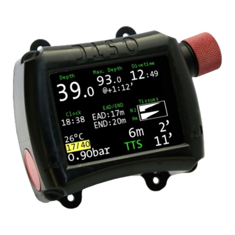
Hollis TX1 He User manual

Doc. 12-4101-r06 (1/21/14)
1
TX1 He OPERATING MANUAL
©2002 DESIGN (2014)
TX1 He
DIVE COMPUTER
OPERATING MANUAL

Doc. 12-4101-r06 (1/21/14)
2
TX1 He OPERATING MANUAL
©2002 DESIGN (2014)
WELCOME.........................................................................................4
WARNINGS........................................................................................5
NOTICES............................................................................................6
FCC ID................................................................................................6
FEATURES & FUNCTIONS............................................................7
ABBREVIATIONS/TERMS......................................................8
DISPLAY ICONS.......................................................................9
CONTROLS..............................................................................10
BUTTON NAVIGATION.........................................................11
ACTIVATION...........................................................................12
MENU SYSTEM......................................................................12
Navigating Menus.....................................................................12
AUDIBLE ALARM..................................................................13
PCINTERFACE.......................................................................14
POWER SUPPLY.....................................................................14
Battery Icon..........................................................................14
BATTERYSTATUS..................................................................14
TX1 He LOW BATTERY WHILE ON SURFACE..............15
TX1 He LOW BATTERY DURING DIVE...........................15
TMT (TRANSMITTER) LOW BATTERY...........................15
OPERATINGMODES.............................................................15
TRANSITION PERIOD..........................................................16
POWER SAVER MODE (PSM).............................................16
NORM SURFACE MODES............................................................17
NORM SURF MAIN................................................................18
NORM SURF ALT SCREENS................................................18
NORM MENU..........................................................................19
GAS MENU..............................................................................19
FLY/DESAT...............................................................................19
Fly/DesatScreen....................................................................20
PLAN MENU............................................................................20
Time Limits...........................................................................20
DepthLimits..........................................................................20
NORM/GAUGE LOG.............................................................21
Log Menu............................................................................21
SET MENU...............................................................................22
OP (OPERATING) MODE.....................................................22
HISTORY (NORM/GAUGE)..................................................23
TX1 He ID.................................................................................23
BATT/TMT...............................................................................23
DIVE PREVIEW......................................................................23
GAS SUB MENUS....................................................................24
GAS SWITCH MENU.......................................................24
SELECT GASES MENU...................................................25
SETGASES.........................................................................26
TRANSMITTERS
SET TRANSMITTER MENU....................................27
SET SERIAL NUMBER (CODE) SCREEN.............27
SET GROUPS
SET A (ALARMS)..............................................................28
SET U (UTILITIES)...........................................................29
SET SAFETY STOP....................................................29
SET GF (GRADIENT FACTOR)...............................30
SET T (TIME/DATE)........................................................31
SET S (SHORTCUT).........................................................31
SET D (DIVE MAIN)........................................................32
SET P (PREVIEW)............................................................33
CONTENTS
DIVE MODE FEATURES...............................................................34
PROXIMITY OF THE TMTS AND TX1 He........................35
Link Interruption Underwater............................................35
WET ACTIVATION.................................................................36
SMARTGLO®BACKLIGHT.................................................36
BAR GRAPHS..........................................................................36
TLBG.........................................................................................36
VARI..........................................................................................36
ALGORITHM..........................................................................37
GRADIENT FACTOR (GF)...................................................37
DEEP STOP (DS).....................................................................37
SAFETY STOP (SS).................................................................38
DIVE TIME REMAINING (DTR).........................................38
No Deco DTR (NDC)........................................................38
O2 Time Remaining (OTR).............................................39
GAS TIME REMAINING (GTR)..........................................39
GTRAlarm........................................................................39
TOTAL ASCENT TIME (TAT)..............................................40
NORM DIVE OP MODE................................................................41
NORM DIVE SCREENS.........................................................42
DEEP STOP PREVIEW...........................................................43
DEEP STOP MAIN..................................................................43
SAFETY STOP MAIN.............................................................43
DECOMPRESSION.................................................................44
DECO CEILING VIOLATION (DCV).................................44
DELAYED DECO VIOLATION (DDV)................................45
DEPTH VIOLATION (DV)....................................................45
GAS SWITCH WARNING.....................................................46
HIGH PO2................................................................................46
LOW PO2.................................................................................46
HIGH 02 SATURATION.........................................................47
VIOLATION GAUGE MODE (VGM)..................................48
NORM DIVE MAIN MENU
Gas Switch...........................................................................48
Isobaric Counter Diffusion (ICD) Warning.....................48
Select Gases.........................................................................48
DepthLimits........................................................................49
Current END (w/O2 NARC Yes/No) WOB......................49
DecoStops............................................................................50
Batt/TMT............................................................................50
GAUGE OP MODE.........................................................................51
GAUGE SURF SCREENS.......................................................52
GAUGE MENU
SWITCH TMT...................................................................53
FLY......................................................................................53
LOG.....................................................................................53
SET MENU.........................................................................53
OP MENU...........................................................................53
HISTORY............................................................................53
TX1 He ID...........................................................................53
BATT/TMT STATUS.........................................................53
DIVEPREVIEW.................................................................53
SWITCH TMT SUB MENU
GAUGE TMT SWITCH....................................................54
SEARCHING FOR TMT..................................................54

Doc. 12-4101-r06 (1/21/14)
3
TX1 He OPERATING MANUAL
©2002 DESIGN (2014)
SET GROUPS
SET A (ALARMS)..............................................................54
SET U (UTILITIES)...........................................................54
SET T (TIME/DATE)........................................................54
SET S (SHORTCUT) MENU............................................55
SET D (DIVE MAIN) MENU...........................................55
SET P (PREVIEW) MENU...............................................56
GAUGE DIVE SCREENS.......................................................57
GAUGE DIVE MAIN..............................................................57
GAUGE DIVE ALT..................................................................57
GAUGE CHANGE TMT SCREENS.....................................58
GAUGE TMT SWITCH..........................................................58
SEARCHING FOR TMT........................................................58
GAUGE DEPTH VIOLATION...............................................58
COMPASS MODE...........................................................................59
COMPASS DISPLAY ICONS.................................................60
OVERVIEW..............................................................................61
COMPASS MENU...................................................................61
NORTH OP MAIN...........................................................61
REFERENCE OP MAIN.................................................62
REFERENCE MENU......................................................62
Set Reference Heading.................................................62
CALIBRATION................................................................63
DECLINATION................................................................64
ALARMS...........................................................................64
REFERENCE....................................................................................65
PCINTERFACE.......................................................................66
PC REQUIREMENTS.............................................................66
CARE AND CLEANING.........................................................67
INSPECTIONS AND SERVICE.............................................67
BATTERYREPLACEMENT..................................................68
Battery Retention..............................................................68
Battery Cover Removal....................................................68
Battery Removal...............................................................68
Inspection...........................................................................69
TX1 He Battery Installation............................................69
Testing................................................................................70
TRANSMITTER BATTERY REMOVAL.............................70
TRANSMITTER BATTERY INSTALLATION...................70
Installing A Transmitter On A Regulator.......................71
Transmitter Compatibility With Nitrox.........................71
ALTITUDE SENSING AND ADJUSTMENT.......................71
RESET DURING A DIVE.......................................................71
WRIST STRAP.........................................................................72
StrapRemoval...................................................................72
Strap Replacement...........................................................72
Adjusting the Shock Cord Version.................................73
TECHNICAL DATA................................................................74
Specications.....................................................................75

Doc. 12-4101-r06 (1/21/14)
4
TX1 He OPERATING MANUAL
©2002 DESIGN (2014)
Welcome to Hollis Gear
and
THANK YOU
for choosing the
TX1 He.
The TX1 He was designed to create a user friendly dive computer that allows the
use of Air, Nitrox, and Trimix. It is a powerful instrument indeed - with a digital
compass, gauge mode, use of up to six transmitters, Gradient Factors, Hollis Dive
Planning Software, and many more features to be discussed within. It is a tool that
will open up many underwater activities to the user.
With the use of the included Hollis Dive Planning Software and data cable, all of the
TX1 He's potential dives can be explored. It is a valuable tool to plan contingencies
and gas requirements. One can also use the software as a learning tool, exploring
different gas choices, proles, and options.
It is imperative to fully understand all the features and functions before pushing to
the limits of the TX1 He. Reaching one's own limits is more likely before reach-
ing the TX1 He's. For this reason, do not neglect the need for proper knowledge,
training, skill, and experience before venturing into new territory. No computer can
replace those attributes.
We at Hollis wish you the best in your diving adventures.

Doc. 12-4101-r06 (1/21/14)
5
TX1 He OPERATING MANUAL
©2002 DESIGN (2014)
! WARNINGS !
Pay special attention to items marked with this Warning symbol.
If your TX1 He stops working for any reason while operating, it is important that you have anticipated this possibility
and are prepared for it. This is an important reason for not pushing the tables, oxygen exposure limits, and a critical
reason to avoid entering decompression, without proper training. If you dive in situations where your trip would be
ruined or your safety would be jeopardized by losing the use of your TX1 He, a backup instrument system is highly
recommended.
It is extremely important that you read this manual and understand completely before attempting to use your new
Hollis dive computer.
Each numeric and graphic display represents a unique piece of information. It is imperative that you understand the
formats, ranges, and values of the information represented to avoid any possible misunderstanding that could result
in error.
Hollis PDCs are NOT for use by commercial divers.
Hollis PDCs are intended for use by divers who have successfully completed a recognized course in SCUBA diving,
and have knowledge of the potential risks and hazards of SCUBA diving.
As with all underwater life support equipment, improper use or misuse of Hollis PDCs can result in serious injury or
death.
If you do not fully understand how to use the PDC, or if you have any questions, you should seek instruction in its
use from your Authorized Hollis Dealer before diving with it.
Remember that technology is no substitute for common sense, and a PDC only provides the person using it with
data, not the knowledge to use it. Remember also that the PDC does not actually measure and test the composition of
your body tissue and blood. Using an Hollis PDC, just as using the U.S. Navy (or other) Decompression Tables, is no
guarantee of avoiding decompression sickness. Every diver’s physiology is different, and can even vary from day to
day. No machine can predict how your body will react to a particular dive prole.
Never share or exchange a dive computer with another diver, or use another dive computer for a repetitive dive.
Special training, equipment, and support are necessary for diving deeper than the maximum recommended depth
limit for recreational diving, generally agreed to be 130 FT (39 M) by most diving instruction authorities.
Decompression diving is inherently hazardous and greatly increases your risk of decompression sickness, even
when performed according to the PDC's calculations.
Oxygen features are intended for use by divers who have successfully completed a recognized course in diving with
enriched nitrogen-oxygen (Nitrox) mixtures, and have knowledge of the potential risks and hazards of diving with
Nitrox. Maximum limits for exposure to oxygen should not be exceeded, and the consequences of CNS (Central Ner-
vous System) Oxygen Toxicity and Pulmonary Oxygen Toxicity can be deadly.
Helium features are intended for use by divers who have successfully completed a recognized course in diving with
Trimix mixtures, and have knowledge of the potential risks and hazards of diving with Trimix.
Diving at high altitude requires special knowledge of the variations imposed upon divers, their activities, and their
equipment by the decrease in atmospheric pressures. Hollis recommends completion of a specialized Altitude train-
ing course by a recognized training agency prior to diving in high altitude lakes or rivers.
Repetitive dives in a series should only be conducted at the same Altitude as that of the rst dive of that series.
Repetitive dives made at a different Altitude will result in an error equal to the difference in barometric pressure, and
possibly a false dive mode with erroneous data.
If an Hollis PDC is activated at an elevation higher than 14,000 feet (4,270 meters), it will immediately shutdown or
revert to Watch Mode.

Doc. 12-4101-r06 (1/21/14)
6
TX1 He OPERATING MANUAL
©2002 DESIGN (2014)
FCC ID: MH8A
FCC COMPLIANCE:
This equipment complies with Part 15 of the FCC Rules. Operation is subject to the following two conditions: 1.) This equipment may not
cause harmful interference. 2.) This equipment must accept any interference received, including interference that may cause undesired opera-
tion.
FCC INTERFERENCE STATEMENT:
This equipment has been tested and found to comply with the limits for an Intentional Radiator, a Class B Digital Device, pursuant to Part 15 of
FCC Rules, Title 47 of the Code of Federal Regulations. These rules are designed to provide reasonable protection against harmful interfer-
ence in a commercial or residential installation. This equipment generates, uses and can radiate radio frequency energy and, if not installed
and used in accordance with the instructions, may cause harmful interference to radio communications.
There is no guarantee that interference will not occur in a particular installation. If this equipment does cause interference to radio or television
reception, which can be deter-mined by turning the equipment off and on, the user is encouraged to try to correct the interference by one or
more of the following measures:• Reorient or relocate the receiving antenna.• Increase the separation between the equipment and receiver.•
Connect the equipment to an outlet on a circuit different from that to which the receiver is connected.• Consult the dealer or an experienced
radio/TV technician.
! WARNING: Changes or modication to this unit not expressly approved by HOLLIS/2002 Design could void the
user's authority to operate the equipment.
NOTICES
LIMITED TWO-YEAR WARRANTY
For details, refer to the Product Warranty Registration Card provided.
COPYRIGHT NOTICE
This operating manual is copyrighted, all rights are reserved. It may not, in whole or in part, be copied, photocopied, reproduced, translated,
or reduced to any electronic medium or machine readable form without prior consent in writing from HOLLIS/2002 Design.
TX1 He Operating Manual, Doc. No. 12-4101
© 2002 Design, 2013
San Leandro, CA USA 94577
TRADEMARK, TRADE NAME, AND SERVICE MARK NOTICE
HOLLIS, the HOLLIS logo type, TX1 He, the TX1 He logo, Gas Time Remaining (GTR), Diver Replaceable Batteries, Graphic Diver Interface,
Tissue Loading Bar Graph (TLBG), Pre-Dive Planning Sequence (PDPS), SmartGlo, Set Point, Control Console, Turn Gas Alarm, and HOLLIS
Computer Interface (HCI) are all registered and unregistered trade-marks, trade names, and service marks of HOLLIS. All rights are reserved.
PATENT NOTICE
U.S. Patents have been issued to protect the following design features: Dive Computer with Wireless Data Transmission (U.S. Patent no.
7,797,124), Air Time Remaining (U.S. Patent no. 4,586,136 and 6,543,444) and Data Sensing and Processing Device (U.S. Patent no.
4,882,678). Set NIBG Alarm and other patents pending. User Setable Display (U.S. Patent no. 5,845,235) is owned by Suunto Oy (Finland).
DECOMPRESSION MODEL
The program within the TX1 He simulates the absorption of inert gases into the body by using a mathematical model. This model is merely a
way to apply a limited set of data to a large range of experiences. The TX1 He dive computer model is based upon the latest research and ex-
periments in decompression theory. Still, using the TX1 He, just as using the U.S. Navy (or other) No Decompression Tables, is no guarantee
of avoiding decompression sickness, i.e. “the bends”. Every diver’s physiology is different, and can even vary from day to day. No machine
can predict how your body will react to a particular dive prole

Doc. 12-4101-r06 (1/21/14)
7
TX1 He OPERATING MANUAL
©2002 DESIGN (2014)
FEATURES/FUNCTIONS

Doc. 12-4101-r06 (1/21/14)
8
TX1 He OPERATING MANUAL
©2002 DESIGN (2014)
ABBREVIATIONS/TERMS
ACTIV = Activation
AL = Alarm
ALT = Alternate
ATA = Standard Atmosphere (unit)
AUD = Audible
AVAIL = Available
BATT = Battery
CAL = Calibrate (compass)
CDT (CD) = Countdown Timer
DCS = Decompression Sickness
DECO = Decompression
DESAT = Desaturation Time
DFLT = Default
DTR = Dive Time Remaining
DURA = Duration (backlight)
E = East (compass)
EDT = Elapsed Dive Time
EL = Elevation (altitude)
END = Equivalent Narcotic Depth
FHe = Fraction of Helium (%)
FO2 = Fraction of Oxygen (%)
FORM = Format (date, time)
FT = Feet (depth)
GAUG = Digital Gauge Dive Mode
GF = Gradient Factor
GLO = Glow (backlight)
GTR = Gas Time Remaining
HCI = Hollis Computer Interface
HIST = History
HT = Hypoxic Threshold
LO = Low (battery)
M = Meters (depth)
MIN = Minutes (time)
MOD = Maximum Operating Depth
N = North (compass)
NDC = No Deco DTR
NDL = No Deco Limit
NE = Northeast (compass)
NO = Number
NORM = Normal Dive Mode
NW = Northwest (compass)
O2 = Oxygen
OTR = O2 DTR
PDC = Personal Dive Computer
PO2 = Partial Pressure of O2 (ATA)
PRESS = Pressure
PSM = Power Saver Mode
REF = Reference (compass)
S = South (compass)
SAFE = Safety (stop)
SE = Southeast (compass)
SEC = Seconds (time)
SN = Serial Number
SURF = Surface
SW = Southwest (compass)
SWCH = Switch (gas)
TAT = Total Ascent Time (deco)
TLBG = Tissue Loading Bar Graph
TMR = Timer
TMT = Transmitter
VIOL = Violation
W = West (compass)
WOB = Work Of Breathing

Doc. 12-4101-r06 (1/21/14)
9
TX1 He OPERATING MANUAL
©2002 DESIGN (2014)
DISPLAY ICONS
FTM
GTR
TAT
min
PO2 BAR PSI
SURF
Dot Matrix
1
2
3
4
5
6
78
9
10
11
12
1 Low Battery Indicator p. 15
2 Log p. 21
3Value is Time
4 Depth ID (units) p. 29
5 Surface Interval p. 16
6 TMT Link p. 27, 35
7 Value is PO2p. 46
8 Pressure ID (units) p. 29
9 Temperature or Heading p. 18, 60
10 Time is Minutes
11 Total Ascent Time p. 40
12 Gas Time Remaining p. 39

Doc. 12-4101-r06 (1/21/14)
10
TX1 He OPERATING MANUAL
©2002 DESIGN (2014)
BUTTONS
The TX1 He utilizes 3 Control Buttons that allow you to select mode options and access specic information.
They are also used to link the Transmitter(s), enter Settings, activate the Backlight, and acknowledge the Audible
Alarm. Throughout this manual they will be referred to as the M, A, and S buttons.
Pressing different combinations of these buttons will navigate through different menus and options of the TX1 He.
The symbols in the table below will illustrate how to proceed through the menus.
SYMBOL MEANING
PRESS THE BUTTON, LESS THAN 2 SEC-
ONDS, THAT THE INDEX FINGER POINTS
TO.
HOLD BUTTON, GREATER THAN 2 SEC-
ONDS, THAT THE INDEX FINGER POINTS
TO.
FTM
GTR
TAT
VARI
TLBG
min
PO2 BAR PSI
SURF
A
M
S
CONTROLS

Doc. 12-4101-r06 (1/21/14)
11
TX1 He OPERATING MANUAL
©2002 DESIGN (2014)
BUTTON NAVIGATION
ACTION BUTTON FUNCTION
Press Button Any Activate TX1 He
PRESS
FTM
GTR
TAT
VARI
TLBG
min
PO2 BAR PSI
SURF
A
M
S
M
•to access Menu
•to scroll up the screen (backward) through Menu selections
FTM
GTR
TAT
VARI
TLBG
min
PO2 BAR PSI
SURF
A
M
S
HOLD
M
•to return to Surface Main
TAP
FTM
GTR
TAT
VARI
TLBG
min
PO2 BAR PSI
SURF
A
M
S
A
•to scroll down the screen (forward) through Menu selections
FTM
GTR
TAT
VARI
TLBG
min
PO2 BAR PSI
SURF
A
M
S
HOLD
A
•to scroll fast through set points
TAP
FTM
GTR
TAT
VARI
TLBG
min
PO2 BAR PSI
SURF
A
M
S
S
• to select, save, or access, an item that is ashing or indicated
by an arrow icon (>)
•to activate Backlight
•acknowledge alarms (while diving)
FTM
GTR
TAT
VARI
TLBG
min
PO2 BAR PSI
SURF
A
M
S
HOLD
S
•to step back from a Menu to a previous screen, Menu, or
Menu item

Doc. 12-4101-r06 (1/21/14)
12
TX1 He OPERATING MANUAL
©2002 DESIGN (2014)
ACTIVATION
To activate the TX1 He, press/release any button.
• The unit will enter Diagnostic Mode displaying all segments of the LCD as 8's, fol-
lowed by dashes ( - - ), then a countdown from 9 to 0. It checks the display and volt-
age to ensure that everything is within tolerance.
• It will also check ambient barometric pressure, and calibrate present depth as 0.
When at 3001 feet (916 meters), or higher, it will adjust depth for the higher altitude.
• After the Diagnostic check, a MY INFO screen will be displayed for 10 sec. showing
a default message, or information that you enter using the PC interface system.
• The NORM Surface Main screen will then be displayed, allowing access to all sur-
face functions.
• If no dive is made within 2 hours, the unit will shut Off. Also see PSM (Power Saver
Mode) on page 16.
Contacts located on the stems of the buttons and pins of the PC Data Port will auto-
matically activate the unit and cause it to enter dive mode when the contacts become
wet and it senses depth of 5 FT (1.5 M). They will not inadvertently activate Surface
Mode such as when in a wet gear bag.
MENU SYSTEM
The Dot Matrix located in the middle of the LCD viewing area is used to display alpha
numeric messages and measured values as well as Menu type systems for selec-
tion of settings and various auxiliary functions. It also serves as the Digital Compass
which can be accessed while viewing Main screens.
There are multiple Menus such as -
• NORM Main Menu
• GAUGE Main Menu
• Compass Menu
• Compass Reference Menu
• Set Gases Menu
• Set Alarms Menu
• Set Utilities Menu
• Set Time Menu
• Set Shortcut Menu
• Set Dive Main Menu
• Set Preview Menu
Upon entering a Menu, movement through it starts at the rst (top) selection, then
continues in a rolling manner down the screen showing selections in groups of up to
4 items.
Navigating Menus > >
• Right Arrow icon ( > ) at the left indicates that the item can be selected.
• Down Arrow icon ( v ) at the right indicates that additional items are available below
(after) those shown.
• Up Arrow icon ( ^ ) at the right indicates that additional items are available above
(before) those shown.
FTM
GTR
TAT
VARI
TLBG
min
PO2 BAR PSI
SURF
TX 1
DIAGNOSTICS
Diagnostic Check
(for 3 seconds then My Info)
CF
FTM
GTR
TAT
min
PO2
SURF
(PZ+)
TLBG
USE OCEANLOG
PC PROGRAM TO
ENTER YOUR DATA
Default Message
(for 10 seconds then Surf Main)
CF
FTM
GTR
TAT
min
PO2 BAR PSI
SURF
(PZ+)
TLBG
SET GF
O2 NARC
GLO DUR
>SAMPLE
>
>
30-80
YES
15 SEC
60 SEC
This item can
be selected
(accessed).
There are more
items above.
There are more
items below.

Doc. 12-4101-r06 (1/21/14)
13
TX1 He OPERATING MANUAL
©2002 DESIGN (2014)
AUDIBLE ALARM
While operating in NORM or GAUGE Mode the Audible will emit 1 beep per second for 10 seconds when alarms
strike, unless it is set Off. During that time, the Audible can be acknowledged and silenced by pressing the S but-
ton (less than 2 seconds).
An LED Warning Light, on the housing, is synchronized with the Audible and ashes as the Audible sounds. It will
turn Off when the Alarm is silenced. The Audible and LED will not be active if the Audible is set OFF (a group A
setting).
Alarms that strike during operations in Compass Mode are described on page 64.
Situations that will activate the NORM/GAUGE 10 second Alarm include -
* Items apply only in NORM mode.
• Gas Time Remaining (GTR) at 5 minutes, then again at 0 minutes.
• Tank Pressure at the Set Point selected.
• Descent deeper than the Depth Alarm Set Point selected.
• Dive Time Remaining at the Set Point selected*.
• Elapsed Dive Time at the Set Point selected.
• PO2 level greater than PO2 max*.
• Low PO2 Warning (0.17 ≤ PO2 < 0.21) and Low PO2 Alarm (PO2 < 0.17)
• O2 accumulation at 240 OTU (80%), then again at 300 OTU (100%)*.
• TLBG at the Set Point selected*.
• Ascent Rate exceeds 60 FPM (18 MPM) when deeper than 60 FT (18 M), or 30 FPM (9 MPM) at 60 FT (18 M)
and shallower.
• Loss of the active Transmitter Link signal for more than 15 seconds during a dive.
• Entry into Decompression Mode (Deco)*.
• Missed Deco Warning (depth is shallower than the deepest prescribed Stop Depth for < 1 minute)*.
• Missed Deco Alarm (depth is shallower than the deepest prescribed Stop Depth for > 1 minute)*.
• Deco Ceiling Violation (Gradient Factor value > 90 for < 5 minutes)*.
• Delayed Deco Violation (Gradient Factor value > 90 for ≥ 5 minutes)*.
• Depth Violation (Depth > 400 FT/120 M in NORM, > 400 FT/120 M in GAUGE).
A single short beep (which cannot be disabled) sounds when -
• After 5 minutes on the surface after the Violation dive.
3 short beeps (which cannot be disabled) sound when -
• Ascent Rate is 51 to 60 FPM (15.1 to 18 MPM) when deeper than 60 FT (18 M), or 26 to 30 FPM (7.5 to 9 MPM)
at 60 FT (18 M) and shallower.
During the following situations, the audible will not turn off when acknowledged -
• Delayed Deco Violation
• Depth Violation

Doc. 12-4101-r06 (1/21/14)
14
TX1 He OPERATING MANUAL
©2002 DESIGN (2014)
PC INTERFACE
Interface with a PC, to allow uploading settings and downloading data, is accomplished by connecting the TX1 He
to a PC USB Port using the special USB Interface Cable.
The software program together with the USB Driver required is on the HCI (Hollis Computer Interface) CD, and
can be downloaded from the Hollis web site. The program's HELP* serves as the user manual which can be
printed for personal use.
*Prior to attempting to Download data from your TX1 He or Upload Settings to it, review the HELP section of the
HCI program. It is recommended to print those sections of HELP that you consider appropriate for your Interface
activities.
The Settings Upload portion of the HCI program can be used to set/change the Set A group (Alarms), Set U group
(Utilities), Set T (Time), etc. using the same Interface System. FO2 and FHe related items must be set using the
control buttons.
Information available for retrieval (download) from the TX1 He to the PC Download portion of the program in-
cludes dive data such as number, surface interval time, maximum depth, elapsed dive time, no deco status, pres-
sure, start date/time, lowest temperature under water, sampling rate, dive prole, and Set Points.
The HCI program also allows upgrade of select versions of the TX1 He's rmware (operating system software) af-
ter which the TX1 He resets all operating data. Since the upgrades require reset of the TX1 He, they are blocked
during 24 hours after dives.
• Refer to page 66 for more details relating to HCI and PC Interface.
POWER SUPPLY
• TX1 He Battery >> (1) 3 vdc, CR2450, Lithium.
• Shelf life >> up to 5 years.
• Use life >> 100 dive hours if (1) 1 hour dive per dive day up to 300 dive hours if (3) 1 hour dives per dive day.
• Transmitter (each) >> (1) 3 vdc, CR2, .75 Ahr, Lithium.
• Use life >> 300 dive hours if (2) 1 hour dives per dive day.
• Replacement >> by user (annual recommended).
Battery Icon (for TX1 He only, does not apply to TMTs):
• Warning >> icon on solid when < 2.75 volts, battery change recommended.
• Alarm >> icon on ashing when < 2.50 volts, change the battery.
BATTERY STATUS
To access, while viewing NORM (or GAUGE) SURF Main >>
FTM
GTR
TAT
min
PO2 BAR PSI
SURF
NORM DIVE 0
aır GAS1
TAP
A
M
S
CF
FTM
GTR
TAT
min
PO2 BAR PSI
SURF
(PZ+)
TLBG
HISTORY
TX1 ID
>BATT / TMT
DIVE PREVIEW
>
A
M
S
TAP
CF
FTM
GTR
TAT
min
PO2 BAR PSI
SURF
(PZ+)
TLBG
>GAS MENU
FLY/DESAT
PLAN
LOG
>
A
M
S
TAP
x 8
CF
FTM
GTR
TAT
min
SURF
SEARCHING
FOR
TMT
CF
FTM
GTR
TAT
min
PO2 BAR PSI
SURF
TLBG
TX1 BATT GOOD
>TMT1 BATT GOOD
TMT2 BATT LOW
TMT3 NOT AVAIL
>
Wait 5 - 30
seconds
Norm Surf Main
(air, dives 0)
Norm Sel Menu Norm Sel Menu
(batt/TMT selected)
Searching Batt/TMT Status

Doc. 12-4101-r06 (1/21/14)
15
TX1 He OPERATING MANUAL
©2002 DESIGN (2014)
TX1 HE LOW BATTERY WHILE ON THE SURFACE
≤2.75 volts (warning level)
• Backlight is completely disabled.
• Battery icon (shell with inner bar) appears solid.
• If a dive is started, the icon is not displayed on the dive mode screens.
• All functions, including Compass Mode, continue to be available.
≤2.50 volts (Too Low - alarm level)
• Battery icon (shell only) will ash for 5 seconds then the unit shuts off completely.
TX1 HE LOW BATTERY DURING A DIVE
≤2.75 volts (warning level)
• Backlight is completely disabled.
• All other functions continue to be available.
• Battery icon is not displayed on the dive mode screens.
• Battery icon (shell with inner bar) appears solid upon entry into Surface Mode.
≤2.50 volts (Too Low - alarm level)
• Backlight is completely disabled.
• All other functions continue to be available during the dive.
• Battery icon is not displayed on the dive mode screens.
• Upon surfacing, the Battery icon (shell only) and graphic CHANGE BATTERY ash
for 10 minutes, then the unit shuts off completely.
TMT(TRANSMITTER) LOW BATTERY
Indication is provided only while on the surface.
≤2.75 volts (warning level)
• The graphics TMT# LOW BATTERY appear solid on the Battery Status screen.
• DC functions continue to be available (surface and dive).
≤2.50 volts (Too Low - alarm level)
• The graphics TMTx LOW BATTERY alternate with the graphics NORM (or GAUGE)
and DIVE xx on the SURF Main screen.
• The graphics TMTx BATTERY and LOW also ash on the Battery Status screen.
• TMT operation continues until Tank Pressure decreases to 50 PSI.
FTM
GTR
TAT
min
PO2 BAR PSI
SURF
NORM
DIVE 0
GAS4
NX 32
if Low Batt
Low Battery
Warning
BAR PSI
SURF
CHANGE
BATTERY
GAS5
NX 36
TLBG GTR
TAT
min
Low Battery
(after surfacing)
CF
FTM
GTR
TAT
min
PO2 BAR PSI
SURF
TMT 1
LOW BATTERY
GAS3
TX 15/45
(PZ+)
TLBG
TMT Low Battery
(Alarm)
OPERATING MODES
NORM Mode >> for Air, Nitrox, and Trimix SCUBA activity with up to 6 Gases/6 TMTs.
GAUGE Mode >> for SCUBA activity with up to 6 TMTs.
If no previous dive has been taken within the past 24 hours, NORM is the default mode upon activation with oth-
ers accessed as described later.
At any time while operating in Surface Modes, operation will enter the Dive Mode selected upon descent to 5 FT
(1.5 M) for 5 seconds.
• When Wet Activation is set Off, Dive Mode will only be activated when the unit is rst activated and operating in
a surface mode.
• When Wet Activation is set On, the selected Dive Mode will activate upon descent regardless of whether is acti-
vated and operating rst.

Doc. 12-4101-r06 (1/21/14)
16
TX1 He OPERATING MANUAL
©2002 DESIGN (2014)
TRANSITION PERIOD, upon surfacing:
Operation shifts from Dive Mode to Surface Mode upon ascent to 2 FT (0.6 M) for 1 second; however, Surface
mode 'screens' will not be available until a Transition time elapses.
The reason for this is that making a descent during the rst 10 minutes after surfacing from a NORM or GAUGE
dive, is a continuation of that dive.
A descent made after the 10 minute (or 1 minute) interval has elapsed is then considered a new dive.
During the rst 10 minutes after surfacing from a NORM or GAUGE dive, the Dive Main screen will be displayed
with Surface Interval time replacing Current Depth. Dive ALT's can be accessed to view other information pertain-
ing to that dive.
POWER SAVER MODE (PSM)
Once 10 minutes elapse, after the 10 minute (NORM or GAUGE) Transition Period on the surface after a dive,
the unit will enter a Power Saver Mode (PSM) which turns the display screen off until a button is pressed at which
time it will turn back on.
During the 10 minutes that the screen is off, all operations continue as normal in the background with current
updated information displayed as soon as the screen comes on again.

Doc. 12-4101-r06 (1/21/14)
17
TX1 He OPERATING MANUAL
©2002 DESIGN (2014)
NORM
SURFACE MODES

Doc. 12-4101-r06 (1/21/14)
18
TX1 He OPERATING MANUAL
©2002 DESIGN (2014)
NORM SURF MAIN, information includes:
> SI (hr:min) with Time (clock) and SURF icons; if no dive yet, this is time since acti-
vation.
> Graphic NORM (operating mode).
> Graphic DIVE and number of dives completed during that operating period, up to
24 (0 if no dive made yet).
> Tank Pressure (or letters SPG if no TMT) with PSI (or BAR) and Link (speaker)
icons, if the Receiver is successfully Linked with an active TMT (Transmitter), 00
ashing after 15 seconds of lost Link.
> Graphic Gas Name: (AIR, NX (FO2) or TX (FO2)/FHe)) and GAS# of the actual
gas.
> TLBG with icon, if any nitrogen after NORM dives.
NORM SURF ALT SCREENS
NORM SURF ALT 1, information includes:
> SI* (hr:min) with Time (clock) and SURF icons.
> Max Depth* with FT (or M) and MAX icons.
> Elapsed Dive Time* (hr:min) with graphic EDT.
> Graphic LAST, indicating that data is from the dive previously conducted while in
NORM mode.
*Dashes if no previous dive.
NORM SURF ALT 2, information includes:
> Altitude graphic, if EL2 (to EL7), blank if Sea level.
> Time of Day (hr:min) with graphic A (or P).
> Temperature with ° icon and graphic F (or C).
NORM SURF ALT 3, information includes:
> Screen titles O2 and GF.
> Current GF value is displayed.
> O2 % accumulation (current) with graphic O2 SAT.
> PO2 MAX (for active gas) set by the user.
> Graphics GAS # and Gas Name: AIR, NX (FO2) or TX (FO2/FHe), for the actual
gas.
FTM
GTR
TAT
min
PO2 BAR PSI
SURF
NORM
DIVE 0
aır GAS1
NORM SURF MAIN
(no dive yet, set for air)
TAP
FTM
GTR
TAT
min
PO2 BAR PSI
SURF
NORM DIVE 2
GAS4
NX 32
TLBG
A
M
S
FTM
GTR
TAT
min
PO2 BAR PSI
SURF
FT MAX EDT
(PZ+)
TLBG
232 83
A
M
S
TAP
CF
FTM
GTR
TAT
min
PO2 BAR PSI
A
(PZ+)
TLBG
12:45
A
M
S
TAP
CF
FTM
PO2 PSI
SURF
43 %O2 SAT
NX 32
(PZ+)
GAS3
A
M
S
TAP
CF
FTM
GTR
TAT
min
BAR
SURF
TX 25/35
(PZ+)
TLBG
GAS5
45%
O2 SAT 58
GF
PO2
Norm Surf Main
(nitrox, dives 2)
Norm Surf
Alt 1
Norm Surf
Alt 2
Norm Surf
Alt 3
back to main

Doc. 12-4101-r06 (1/21/14)
19
TX1 He OPERATING MANUAL
©2002 DESIGN (2014)
NORM MENU
Selections include:
> GAS MENU.
> FLY/DESAT.
> PLAN.
> LOG.
> SET MENU.
> OP MODE.
> HISTORY
> TX1 ID.
> BATT/TMT
> DIVE PREVIEW
GAS MENU
The Gas Menu selection provides access to a listing of sub menus that contain items
specic to the selection and use of gases and tranmsitters.
Gas Menu, information includes:
> Graphics Gas and MENU with selections -
> GAS SWITCH.
> SELECT GASES.
> SET GASES.
> SET TMT.
These gas sub menus are described after the Main Menu items (starting on page 24)
FLY/DESAT
FLY Time is a count down timer that begins counting down 10 minutes after surfacing
from a dive from 23:50 to 0:00 (hr:min).
DESAT Time, also a count down timer, provides calculated time for tissue desatura-
tion at sea level taking into consideration the algorithm and gradient factor setting.
DESAT Time also begins counting down 10 minutes after surfacing from a dive,
counting down from 23:50 (max) to 0:00 (hr:min).
When the DESAT time reaches 0:00, which will generally occur prior to the FLY count
down reaching 0:00, it will remain on the display until the FLY count down reaches
0:00.
> DESAT is not displayed after a Gauge or Violation dive.
> Desaturation requiring Times greater than 24 hours will display > 24 HR DESAT.
> In the event that Time to Desaturate still remains at the end of 24 hours, the unit is
to turn off. Addtionally, any inert gas and O2 calculations are to clear.
> When other screens are accessed, the FLY and DESAT countdowns continue in
the background.
TAP
FTM
GTR
TAT
min
PO2 BAR PSI
SURF
NORM DIVE 2
GAS4
NX 32
TLBG
A
M
S
CF
FTM
GTR
TAT
min
PO2 BAR PSI
SURF
(PZ+)
TLBG
>GAS MENU
FLY/DESAT
PLAN
LOG
>
TAP
A
M
S
TAP
TAP
to select
to scroll cursor (>)
downup
or
Norm Surf Main
(nitrox 32, dives 2)
Surf Main Sel Menu

Doc. 12-4101-r06 (1/21/14)
20
TX1 He OPERATING MANUAL
©2002 DESIGN (2014)
Fly/Desat, information includes:
> Graphics FLY and DSAT with countdown times (hr:min) and Time (clock) icon,
dashes if no dive yet.
PLAN MENU
Selections include:
> Time Limits.
> Depth Limits.
Time Limits
No Deco Time Limits (NDLs) and O2 Time Limits (OTLs) in Plan Mode are based on
the Algorithm with gradients, the FO2 set for the actual gas, FHe set for the actual
gas, and residual inert gas (or O2) remaining from previous NORM dives. FO2 and
FHe set for other Gases are not used for Plan calculations.
Time Limit screens will sequence through Depths from 30 to 190 FT (9 to 57 M),
or the Max Depth that will allow theoretical No Deco Dive Time or OTL of at least 1
minute based upon the previous dive proles in a series of repetitive dives and taking
into account descent and ascent rates of 60 FPM (18 MPM). Depths where the PO2
of the actual gas is > 1.6 shall not be listed.
Time Limits Screen, information includes:
> Plan Depth value with FT (or M) icon - from 30 to 190 FT (9 to 57
M) in increments of 10 FT (3 M).
> Max Depth allowed with FT (or M) and MAX.
> Graphic NDC (or OTL) with Dive Time allowed (min).
> Graphics GAS NAME and GAS# for the actual gas.
> Depth from 30 to 190 FT (9 to 57 M) in increments of 10 FT (3 M).
Depth Limits
The Depth Limits Screen will help determine what the Maximum Operating Depth
(MOD) of the selected gas is. If the actual gas is trimix and the corresponding alarms
are turned on (END Alarm, WOB alarm, and HT alarm), this screen will tell you what
the depth limits are - in relation to those settings.
Depth Limits, information includes:
> Graphic PLAN.
> MOD* (Maximum Operating Depth) - determined by PO₂ settings.
> END** - depth limit where current gas is equal to the set Equivalent Nitrogen Depth
(set in Alarms Menu).
> WOB** - depth limit where current gas is equal to the set Work Of Breathing (set in
Alarms Menu).
> HT (Hypoxic Threshold)** - depth where the PO2 of the gas equals 0.21 ATA.
> Active gas mix.
> Graphics GAS NAME and GAS# for the actual gas
> Graphic DPTH.
NOTE: If any value is greater than 400 ft (120 m), 400 ft (or 120 m) shall be
displayed. Zero shall be displayed if any calculated value is negative.
CF
FTM
GTR
TAT
min
PO2 BAR PSI
SURF
(PZ+)
TLBG
23:50
9:59
FLY/DESAT
CF
FTM
GTR
TAT
min
PO2 BAR PSI
SURF
(PZ+)
TLBG
>TIME LIMITS
DEPTH LIMITS
TAP
A
M
S
TAP
TAP
to select
to scroll cursor (>)
downup
or
CF
FTM
GTR
TAT
min
PO2 BAR PSI
SURF
(PZ+)
TLBG
GAS3
TX 18/45
FT MAX NDC
90 15
TIME LIMITS
CF
FTM
GTR
TAT
min
PO2 BAR PSI
SURF
(PZ+)
TLBG
MOD END WOB HT
180 130 97 14
FEET
GAS5
TX 15/45
DEPTH LIMITS
* Item applies only for AIR or NX.
** No value shown if that alarm is set
to off.
Other manuals for TX1 He
1
Table of contents
Other Hollis Diving Instrument manuals

Hollis
Hollis Prism 2 User manual

Hollis
Hollis LX Wing Series User manual

Hollis
Hollis Prism 2 User manual

Hollis
Hollis DG02 User manual

Hollis
Hollis Explorer User manual

Hollis
Hollis LTS BCD User manual

Hollis
Hollis DG03 Service manual

Hollis
Hollis DG05 User manual

Hollis
Hollis Prism 2 User manual

Hollis
Hollis Prism 2 User manual