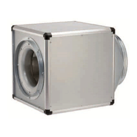
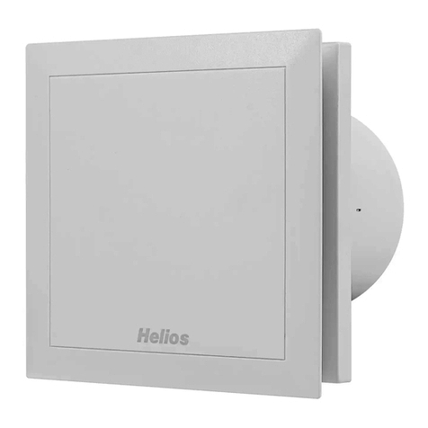
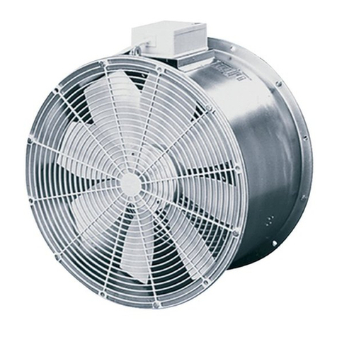
RADAX-Kanalventilatoren KVD.. EX
RADAX-Rectangular fans KVD.. EX
3
EINBAU
- Einbau und Wartung gemäß den geltenden nationalen Vorschriften. Für
Mitglieder von CENELEC in den europäischen Ländern sollen die nationalen
Normen bezogen auf EN 60079-14 und EN 60079-17 berücksichtig werden.
- Die Ventilatoren können an 400V / 3 Phasen (Y) oder 230V / 3 Phasen (D) an-
geschlossen werden. Siehe Tabelle 1 und Anschlussplan in Abb. 1.
- Das Kabel des Motors muss direkt an den Klemmenkasten angeschlossen wer-
den (Klemmenkasten im Lieferumfang enthalten und ist am Aufstellungsort
anzubringen).
- Überprüfung auf mögliche Schäden am Ventilator. Ein schadhafter Ventilator
darf unter keinen Umständen installiert werden.
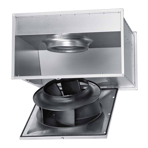
- Überprüfung der Abstände zwischen Laufrad und Ansaugdüse und zwischen
Laufrad und Motorgehäuse. Der Abstand muss mindestes 4 mm betragen
(Abb.3).
- Installation und Inbetriebnahme dürfen nur durch autorisiertes Fachpersonal in
Übereinstimmung mit den Anweisungen und Vorschriften durchgeführt wer-
den. Der elektrische Anschluss muss gemäß EN 60079-14 vorgenommen
werden, welcher mit den Sicherheitsbestimmungen über Starkstrom überein-
stimmt.
- Anschluss gemäß Schaltplan.
- Der Ventilator muss geerdet werden.
- Ein externer Motorschutz muss angeschlossen werden (siehe Abb.2 als
Zubehör). Wird der Motorschutz in der gleichen Zone wie der Ventilator instal-
liert, muss dieser die gleiche ATEX Klassifikation haben.
- Vor der Inbetriebnahme müssen die Ventilatoren an einen Lüftungskanal mon-
tiert oder mit einem Schutzgitter ausgestattet werden, um Kontakt mit beweg-
lichen Teilen zu verhindern (EN 294).
- Die Ventilatoren sind nur für starre Installation bestimmt.
- Die Ventilatoren müssen sicher installiert werden, ohne Risiko herunterzufallen,
dürfen keinen Schwingungen ausgesetzt sein oder selbst keine Schwingun-
gen verursachen.
- Die Ventilatoren müssen über einen Flansch an den Lüftungskanal ange-
schlossen werden, wenn die Installation Schwingungen verursacht.
- Schutzmaßnahmen müssen getroffen werden, um Material daran zu hindern
in den Ventilator zu fallen, wenn dieser vertikal montiert ist.
Mindestens IP 20 < Ø 12,5 mm auf der Ansaugseite und IP 10 < Ø 50 mm auf
der Ausblasseite.
- Der Ventilator muss gemäß dem Luftrichtungsaufkleber installiert werden.
- Der Ventilator ist so einzubauen, dass er für Wartungsarbeiten frei zugänglich
ist.
INBETRIEBSETZUNG
Vor der Inbetriebsetzung vergewissern Sie sich, dass:
- der Ventilator installiert ist und elektrisch richtig geerdet und an ein Motor-
schutzgerät anschlossen ist.
- keine fremden Gegenstände im Ventilator plaziert sind und kein Geräusch
beim Anlauf auftritt.
- die Drehrichtung mit dem Laufrichtungsaufkleber übereinstimmt. Ist dieser
falsch, 2 Phasen miteinander vertauschen und die Drehrichtung stimmt.
- der Strom nicht höher ist, als auf dem Aufkleber angegeben ist.
KONDENSWASSERBILDUNG
Bei periodischem Betrieb, bei feuchten und warmen Fördermitteln und durch
Temperaturschwankungen (Aussetzbetrieb), kann innerhalb des Motors und
des Ventilators Kondensat entstehen, dessen Abfluss sichergestellt sein muss.
In Abhängigkeit von Einbaulage, Einsatz und evtl. Anfallmenge von Kondensat
sind entsprechende Kondensatbohrungen erforderlich und ggf. bauseitig anzu-
bringen.
KONFORMITÄTSBESCHEINIGUNG SP07ATEX3128X
1. Der thermische Motorschutz durch eingebaute Kaltleiter in den Motoren, wird
an ein Auslösegerät (zertifiziert gemäß der Richtlinie 94/9/EG) angeschlos-
sen. Es trennt sofort den Motor vom Stromnetz nach Auslösen der PTC-
Sensoren.
2. Wenn die Ventilatoren in einem Kanalnetz installiert werden, wird die Schutz-
art IP 20 an der Ansaugseite und IP 10 an der Ausblasseite für das Kanalnetz
erfüllt. Teile, die zu dieser Schutzart beitragen, sollen ein geeignetes Design in
Bezug auf Stärke und Material haben.
3. Das Kabel ist fest angeschlossen, mechanisch und von anderen Umweltein-
flüssen geschützt, um den Explosionsschutz zu gewährleisten. Der An-
schluss des freien Kabelendes soll, in Übereinstimmung mit den gültigen
Installationsvorschriften, explosionsgeschützt sein.
4. Der angegebene Stromwert auf dem Ventilatorlabel darf nicht überschritten
werden.
- The fans must be connected to duct via a flange, if installation cause
vibrations.
- Precautions must be taken to prevent material to fall into the fan, when
vertically mounted. Minimum IP 20 < Ø12,5 mm at the inlet side and IP 10 < Ø
50 mm at the outlet side.
- The fan must be installed according to the air direction label.
- The fan should be installed in a way that makes service and maintenance easy.
OPERATION
Before starting, make sure that:
- the fan is installed and electrically connected in the correct way to ground and
a motor protection.
- no foreign objects are place in the fan and no noise appears when starting the
fan.
- the rotation direction are according to the label. If the fan rotates in wrong
direction, change place of 2 phases and rotation direction will be right.
- the current does not exceed what is stated on the label.
CONDENSATION – WATER DEVELOPMENT
In case of periodical use, moist and warm media and through temperature
variations (intermittent service) condensate is built up in the motor and its
draining off must be ensured. The motor is equipped with condensation pores.
In case of condensation in the fan or ducting a condensation pore has to be
drilled at the appropriate position of the casing. Under no circumstances must
the motor be covered by moisture.
CONDITIONS OF CERTIFICATE SP07ATEX3128X
1. The PTC thermal protection circuits of the motors shall be connected to a
triggering device certified according to Directive 94/9/EC, which shall im-
mediately disconnected the motor from main supply upon activation of the
PTC-sensors.
2. When the fans are installed in a duct system the degree of protection IP 20 at
the inlet side and IP 10 at the outlet side shall be fulfilled for the duct system.
Parts that contribute to this protection shall have a suitable design with
respect to strength and material.
3. The cable shall be permanently installed, mechanically protected and
protected from other environmental stress in order to ensure explosion
protection. The connection of the free end of the cable shall be explosion
protected according to the valid installation regulations.
4. The stated current on the marking sign of the fan must not be exceeded.
ELECTRICAL CONNECTION
ATTENTION: Electrical connection may only be carried out with the
equipment fully isolated form the supply.
All work may only be carried out by a qualified person. All relevant national and
international safety and installation regulations are to be adhered to. Power
supply voltage and frequency must correspond to the data given on the motor
rating plate. An appliance is required for cut off from the supply with a minimum
of 3 mm contact opening of each pole.
For maintenance an all-pole disconnecting isolator should be installed
directly by the fan.
The introduction of the power cable must be done so that in case of water, entry
along the power cable is impossible. The cable may not touch sharp objects.
The electrical connection must be carried out in accordance with the relevant
wiring diagram.
PUTTING INTO OPERATION
The following checks are to be carried out:
– Check for operation according to the intended purpose of the fan.
– Compare power supply voltage with data on the rating plate
(voltage fluctuation according to IEC 38 are to be kept).
– Check if fan is securely mounted.
– Check all parts especially screws and nuts for tight fit.
– Check on vibration free operation.
– Check freewheeling of moving parts.
– Check on correct direction of rotation and correct direction of air flow.
– Check earth connection.
– Compare current consumption with data on the rating plate.
– Check that measured data is not allowed to
exceed the value on the fan’s nameplate.
– Rated current must not be exceeded at rated voltage.
– Check that the motor is running smoothly (no abnormal noise).
– Test protective conductor connection.


