HELIX 8200 Training manual

HELIX TECHNOLOGY CORPORATION
http://www.helixtechnology.com
C
HELIX TECHNOLOGY CORPORATION
-
TI CRYOGENICS
8200 Compressor
Installation, Operation and Service
Instructions
8040353
Rev. 101 (11/2001)
View our inventory

The information in this document is believed to be accurate and reliable. However,
Helix Technology Corporation, cannot accept any financial or other responsibilities that may
result from the use of this information. No warranties are granted or extended by this document.
Helix Technology Corporation reserves the right to change any or all
information contained herein without prior written notice. Revisions may be issued at the time of
such changes and/or deletions.
Any duplication of this manual or any of its parts without expressed written permission from
Helix Technology Corporation is strictly prohibited.
Any correspondence regarding this document should be forwarded to:
Helix Technology Corporation
Mansfield Corporate Center
Nine Hampshire Street
Mansfield, Massachusetts 02048-9171 U.S.A.
Telephone: (508) 337-5000
FAX: (508) 337-5464
The following Helix Technology Corporation trademarks and service marks may appear in this
document:
All other trademarks or registered trademarks are the property of their respective holders.
Copyright© 2001 Helix Technology Corporation Printed in U.S.A.
Conductron™ Convectron®Cryodyne®Cryogen®
Cryogenerator®Cryo-Torr®CTI-Cryogenics®FastRegen™
GOLDLink®Granville-Phillips™ GUTS®Helix Technology.. Your
Vacuum ConnectionSM
Helix®Micro-Ion®Mini-Ion™ On-Board®
RetroEase®RetroFast®Stabil-1®Stabil-Ion®
ThinLine™ TurboPlus®Vacuum AssuranceSM

8200 Compressor
P/N 8040353 iii
C
HELIX TECHNOLOGY CORPORATION
-
TI CRYOGENICS
Table of Contents
Section 1 - Introduction
General . . . . . . . . . . . . . . . . . . . . . . . . . . . . . . . . . . . . . . . . . . . . . . . . . . . . . . . . . . . 1-1
Installation, Operation and Servicing Instructions . . . . . . . . . . . . . . . . . . . . . . . . . 1-1
Section 2 - Inspection
Packaging of the System . . . . . . . . . . . . . . . . . . . . . . . . . . . . . . . . . . . . . . . . . . . . . 2-1
The Compressor . . . . . . . . . . . . . . . . . . . . . . . . . . . . . . . . . . . . . . . . . . . . . . . . . . . . 2-1
Section 3 - Installation
Compressor Installation . . . . . . . . . . . . . . . . . . . . . . . . . . . . . . . . . . . . . . . . . . . . . . 3-1
Preparing the Compressor Input-Power Cable . . . . . . . . . . . . . . . . . . . . . . . . . . . . 3-1
Cooling Water Requirements (Water-Cooled Compressors Only) . . . . . . . . . 3-3
Cooling Water: General Considerations . . . . . . . . . . . . . . . . . . . . . . . . . . . . . . 3-4
Cooling Water: Flow and Pressure Requirements . . . . . . . . . . . . . . . . . . . . . . 3-4
Cooling Water: Temperature Rise . . . . . . . . . . . . . . . . . . . . . . . . . . . . . . . . . . 3-6
Final Preparation of Compressor . . . . . . . . . . . . . . . . . . . . . . . . . . . . . . . . . . . . . . . 3-7
Connecting the Compressor to the Cold Head . . . . . . . . . . . . . . . . . . . . . . . . . . . . . 3-7
Section 4 - Maintenance Procedures
Scheduled Maintenance . . . . . . . . . . . . . . . . . . . . . . . . . . . . . . . . . . . . . . . . . . . . . . 4-1
Removing the Compressor Adsorber . . . . . . . . . . . . . . . . . . . . . . . . . . . . . . . . . 4-1
Installing the Compressor Adsorber . . . . . . . . . . . . . . . . . . . . . . . . . . . . . . . . . 4-3
Unscheduled Maintenance . . . . . . . . . . . . . . . . . . . . . . . . . . . . . . . . . . . . . . . . . . . . 4-3
Suggested Unscheduled Maintenance Equipment . . . . . . . . . . . . . . . . . . . . . . . 4-3
Adding Helium Gas . . . . . . . . . . . . . . . . . . . . . . . . . . . . . . . . . . . . . . . . . . . 4-4
Helium Circuit Decontamination . . . . . . . . . . . . . . . . . . . . . . . . . . . . . . . . . . . . . . . 4-5
Appendix A - Customer Support Information
Appendix B - Troubleshooting Procedures
Appendix C - Electrical Schematics for 8200 Compressor
Appendix D - Components in the Electrical Control Module of the 8200 Com-
pressor

8200 Compressor
iv P/N 8040353
C
HELIX TECHNOLOGY CORPORATION
-
TI CRYOGENICS
Table of Contents (continued)
Appendix E - Flow Diagrams for 8200 Air-Cooled and Water-Cooled Compres-
sors Figures
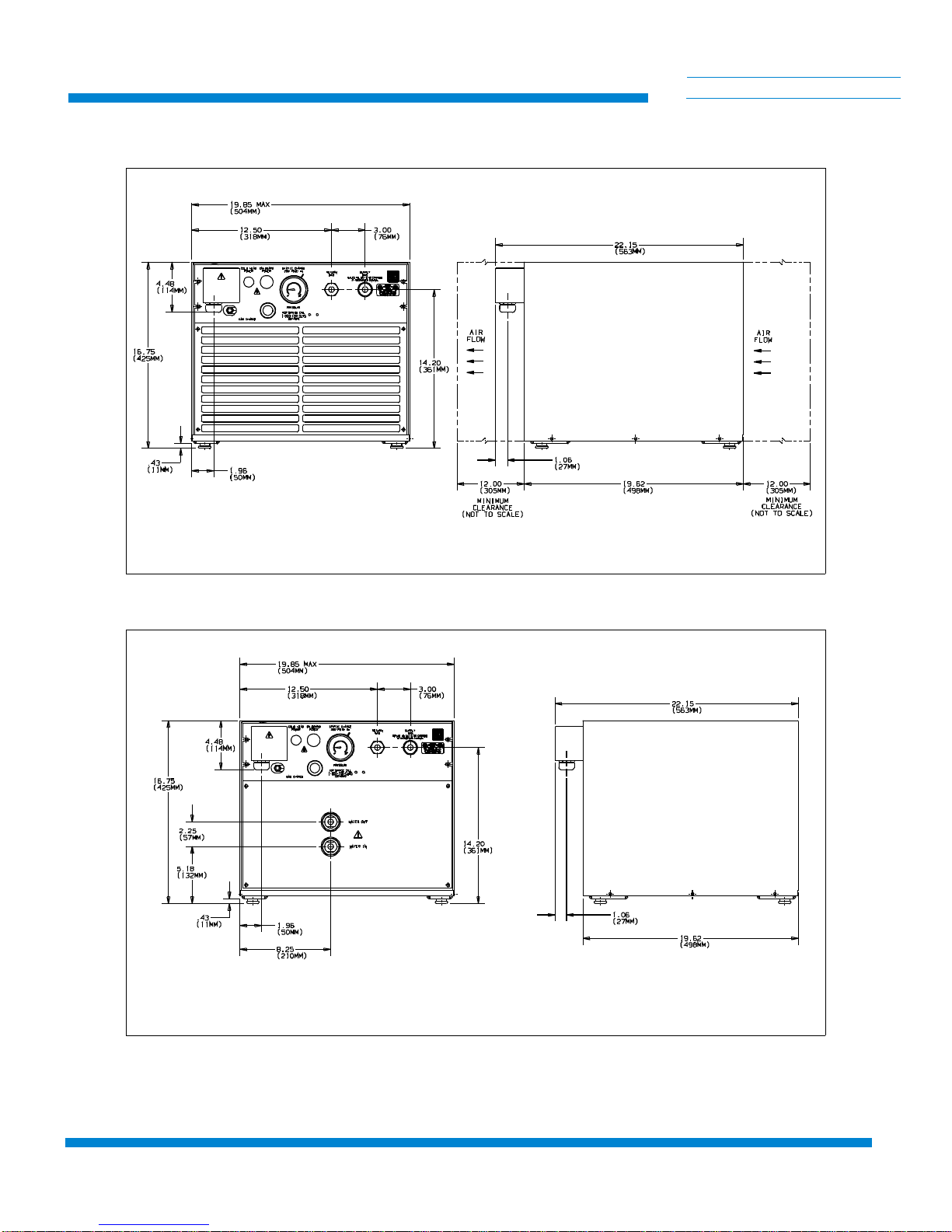
Figure 1-1: Air and Water Cooled 8200 Compressor Dimensions . . . . . . . . . . 1-2
Figure 1-2: Component Locations . . . . . . . . . . . . . . . . . . . . . . . . . . . . . . . . . . . 1-3
Figure 3-1: Electrical Terminal Enclosure with Cover in Place . . . . . . . . . . . . 3-2
Figure 3-2: Assembly of Conductors to Terminal Block . . . . . . . . . . . . . . . . . 3-3
Figure 3-3: 8200 Compressor Cooling Water Flow and Pressure Requirements 3-5
Figure 3-4: 8200 Compressor Water Discharge Temperature Increase (°F) . . . 3-6
Figure 3-5: Typical 8200 Compressor Installation . . . . . . . . . . . . . . . . . . . . . . 3-9
Figure 4-1: Disconnecting/Connecting the Adsorber Self-Sealing Coupling . . 4-2
Figure 4-2: Removing the Adsorber from the Compressor . . . . . . . . . . . . . . . . 4-2
Figure C-1: 8200 Compressor Electrical Schematic P/N 8032563P001
Rev. 100 . . . . . . . . . . . . . . . . . . . . . . . . . . . . . . . . . . . . . . . . . . . . . C-2
Figure C-2: 8200 Compressor Electrical Schematic P/N 8032564P001 Rev. D C-3
Figure D-1: Components in the Electrical Control Chassis of the
8200 Compressor Three-Phase Scott-T Configuration . . . . . . . . . . D-1
Figure D-2: Components in the Electrical Control Chassis of the
8200 Compressor - Single-Phase RC Configuration . . . . . . . . . . . D-2
Figure E-1: Flow Diagram of the 8200 (Air-Cooled) Compressor . . . . . . . . . . E-2
Figure E-2: Flow Diagram of the 8200 (Water-Cooled) Compressor . . . . . . . . E-3
Tables
Table 1-1: Power Requirements (Steady-State Conditions) . . . . . . . . . . . . . . . 1-4
Table 1-2: General Specifications . . . . . . . . . . . . . . . . . . . . . . . . . . . . . . . . . . . 1-4
Table 3-1: Voltage Specifications . . . . . . . . . . . . . . . . . . . . . . . . . . . . . . . . . . . 3-7
Table A-1: CTI-CRYOGENICS Product Customer Support Centers . . . . . . . . A-2
Table B-1: Compressor Troubleshooting Procedures . . . . . . . . . . . . . . . . . . . . B-1

8200 Compressor
P/N 8040353 1-1
C
HELIX TECHNOLOGY CORPORATION
-
TI CRYOGENICS
Section 1 - Introduction
General
The manual provides instructions for installing, operating and servicing the
8200 Compressor. This compressor is available in two versions: air-cooled,
P/N 8032549G001/G002 and water cooled, P/N803255G001/G002.
If you are installing or operating a Cryo-Torr or On-Board System you
should also have available the appropriate cryopump or refrigerator.
When you purchase a system, you will receive two manuals necessary for
system installation, plus a loose- leaf binder with index tab separators,
allowing you to compile a complete indexed system notebook.
Installation, Operation and Servicing Instructions
Installation, Operation and Servicing Instructions for your 8200
Compressor provide easily accessible information. All personnel with
installation, operation, and servicing responsibilities should become
familiar with the contents of these instructions to ensure high quality, safe,
reliable performance.
Introduction
1-2 P/N 8040353
C
HELIX TECHNOLOGY CORPORATION
-
TI CRYOGENICS
Figure 1-1: Air and Water Cooled 8200 Compressor Dimensions
Air Cooled
Water Cooled

8200 Compressor
P/N 8040353 1-3
C
HELIX TECHNOLOGY CORPORATION
-
TI CRYOGENICS
Figure 1-2: Component Locations
16
15
14
13
17
18
10
11
123456 7
8
9
Rear View - Water Cooled
Rear View - Air Cooled
Front View - Air and Water Cooled
1. Compressor Input Power Block
2. Cold Head Power Receptacle
3. On-Board Power Receptacle
4. Helium Gas Fitting and Charge Valve
5. Helium Supply Pressure Gauge
6. Helium Gas Return Connector
7. Helium Gas Supply Connector
8. Rear Panel
9. Rear Grill
12
10. Cooling Water Output
11. Cooling Water Input
12. Rear Plate
13. 50/60 Hz Frequency Selector Switch
14. 208/220 Voltage Range Selector
Switch
15. Resettable Circuit Breakers
16. Compressor ON/OFF Switch
17. Front Panel
18. Front Grill
LEGEND

Introduction
1-4 P/N 8040353
C
HELIX TECHNOLOGY CORPORATION
-
TI CRYOGENICS
Table 1-1: Power Requirements (Steady-State Conditions)
Part Number Cooling Phase Hz Operating Voltage
Range
Nominal
Operating
Current
8032549G001 Air
Air 3
350
60 180-220
198-250 10A
10A
8032549G002 Air
Air 1
150
60 180-220
198-250 10A
10A
8032550G001 Water
Water 3
350
60 180-220
198-250 8.5A
8.5A
8032550G002 Water
Water 1
150
60 180-220
198-250 8.5A
8.5A
Table 1-2: General Specifications
Specification Description
Weight 140 lbs (63.5 kg) approximate
Weight
(shipping) 145 lbs (70.5 kg) approximate
Power
consumption 2.0 kw, nominal operating(water), 2.1 kw nominal operating
(air)
Compressor input-power
cable
(customer-supplied)
Recommended type SO-4 conductor, 600V, neoprene jacket
and 14-gauge wire.
Install per Figure C-1, Electrical Schematic diagram, ensuring
compliance with all national, state and local standards.
Helium pressure Static: 245-255 psig (1688-1757 kPa) at 70 to 80°F (21 to
27°C)
Supply: nominal operation: 270-290 psig (1860-2000 kPa) at
operating temperature.
Ambient operating
temperature range 50 to 100°F (10 to 38°C)

8200 Compressor
P/N 8040353 1-5
C
HELIX TECHNOLOGY CORPORATION
-
TI CRYOGENICS
Interface Cold head power receptacle: Mates with plug on cold head
power cable.
On-Board power receptacle: Mates with plug on cold-head
power cable.
Compressor input-power terminal block enclosure: Mates with
input power cable, fabricated by customer or available from
CTI-CRYOGENICS.
Gas-supply connector: 1/2-inch self-sealing coupling
Gas-return connector: 1/2-inch self-sealing coupling
Adsorber service schedule Replace every 12 months.
Cooling water require-
ments (water cooled only) 100°F (38°C) maximum discharge temperature
Refer to Figures 3-5 and 3-6 for parameters.
Table 1-2: General Specifications
Specification Description

8200 Compressor
P/N 8040353 2-1
C
HELIX TECHNOLOGY CORPORATION
-
TI CRYOGENICS
Section 2 - Inspection
Packaging of the System
A High-Vacuum Pump or Refrigerator System is packaged in separate
cartons for each major component. An Installation, Operation, and
Servicing Manual is included in the carton for the component packaged in
that carton.
The Compressor
On receipt, remove the 8200 Compressor from its shipping carton and
inspect the compressor for evidence of damage as described in this Section.
1. Unpack and remove the compressor from its shipping carton.
2. Check the carton contents. It should contain:
a. 8200 Compressor (air cooled or water cooled).
b. Compressor Manual P/N 8040353.
3. After unpacking, inspect the compressor for evidence of damage as
follows:
a. Inspect the compressor overall exterior for damage.
b. Report damage to the shipper at once.
c. Retain shipping cartons for storage or return shipment.
When installing your system, CTI recommends that as you unpack a
component, you perform an inspection and the necessary tasks for system
installation for the component according to the manual included with the
component. Final system installation and operation will be performed
following procedures in the high-vacuum pump or refrigerator manual.
4. Check the helium pressure gauge. The gauge should indicate 250 psig
(1725 kPa) minimum at 70°F. If additional gas pressure is required,
follow the instructions in Adding Helium Gas.

8200 Compressor
P/N 8040353 3-1
C
HELIX TECHNOLOGY CORPORATION
-
TI CRYOGENICS
Section 3 - Installation
Compressor Installation
Installation of your compressor requires no special tools other than those
supplied in the Installation and Scheduled Maintenance Tool Kit.
Preparing the Compressor Input-Power Cable
To supply input power to the 8200 compressor requires the fabrication of a
600-volt power cable that has an SO-4 conductor, 600-volt rating neoprene
jacket and 14-gauge or 2.3 mm2wire. Proceed as follows:
WARNING
Do not connect the compressor to the power source at this time. All of
the preparation must be completed and all panels reinstalled before elec-
trically connecting the compressor.
Unit must be wired by an authorized electrician in accordance with the
national Electrical Code, ANSI/NFPA 70-1987, as well as the local
codes. This shall include installation of a readily accessible disconnect
device into the fixed wiring supplying power.
An insulated earthing conductor that is identical in size, insulation mate-
rial and thickness to the earth and unearth branch circuit supply conduc-
tors, except that it is green with or without one or more yellow stripes is
to be installed as part of the branch circuit which supplies the unit or sys-
tem. The earthing conductor described is to be connected to the earth at
the service equipment, or supplied by a separately derived system at the
supply transformer or generator.
1. Prepare the input power cable by terminating each of the four
conductors with a #10 ring terminal. Follow the terminal
manufacturer’s instructions to insure proper crimping.
2. Disassemble the electrical terminal enclosure cover, mounted on
the compressor rear panel, as shown in Figure 3-1. Remove the two
screws securing the cover and lift it off.
3. If necessary, back off strain relief screws.

Installation
3-2 P/N 8040353
C
HELIX TECHNOLOGY CORPORATION
-
TI CRYOGENICS
4. Thread input power cable end up through the strain relief into the
enclosure.
5. Attach the power conductors onto the appropriate terminals of the
terminal block.
a. For three-phase hookups, attach the three power leads to ter-
minals X, Y and Z.
b. For single-phase hookups, attach the two power leads to ter-
minals X and Y. DO NOT USE TERMINAL Z.
6. Tighten all terminals to 18-22 in.-lbs. torque.
7. Tighten down screws on strain relief.
CAUTION
Ensure that strain relief is tightened down on the outer insulation of the
input power cable and that the cable does not slide.
8. Remount the terminal enclosure cover and secure with two screws.
9. Refer to Final Preparation of Compressor for correct phasing
checkout procedure.
WARNING
Insure that the ground wire is returned to a suitable ground in a non-
interrupting manner.
Figure 3-1: Electrical Terminal Enclosure with Cover in Place
Cover Screws

8200 Compressor
P/N 8040353 3-3
C
HELIX TECHNOLOGY CORPORATION
-
TI CRYOGENICS
Figure 3-2: Assembly of Conductors to Terminal Block
Cooling Water Requirements (Water-Cooled Compressors Only)
If flexible water hose connections are used, install the barbed fittings
supplied with the compressor on the input and output connections:
1. Apply a light coating of standard plumbing thread sealant on
the barbed fitting threads.
2. Tighten fittings on 1/2-inch FPT input and 1/2-inch FPT output con-
nections. DO NOT OVERTIGHTEN.
3. Connect flexible hoses to the fittings and secure with hose clamps.
If hard piping is desired, install the water lines directly onto the compressor
1/2-inch FPT input and output connections. DO NOT OVERTIGHTEN.
CAUTION
Check water connections for leaks.
Power Cable
Ground Screw
X
Y
Z(not used for single phase)

Installation
3-4 P/N 8040353
C
HELIX TECHNOLOGY CORPORATION
-
TI CRYOGENICS
Cooling Water: General Considerations
NOTE: Adjust your water flow to maintain an optimum discharge water
temperature of 85°F with a minimum input pressure of 2 psig. For detailed
water requirements, see below.
1. Cooling water must meet flow and pressure requirements as
indicated in the following subsections.
2. Cooling water having a pH value of 6.0 to 8.0 and a calcium-car-
bonate concentration of less than 75 ppm, the quality of typical
municipal drinking water, is acceptable. If the cooling water has a
pH value lower than 6.0 or a calcium- carbonate concentration
higher than 75 ppm, water conditioning may be required.
3. To conserve water, the cooling water should be shut off when the
compressor is not running.
CAUTION
If cooling water below 45°F (7°C) is allowed to run through the
compressor while the compressor is not operating, the compressor oil
will change viscosity and thicken, causing the compressor to overheat
and shut off at startup. In this event, repeatedly restart the compressor
and allow it to run until it has shut off several times. The oil
temperature will rise and thereby allow continuous compressor
operation.
4. Drain and purge water from the compressor before shipping it back
to the factory or subjecting it to freezing conditions. Purge water
from the compressor by blowing compressed air, regulated to 30 to
40 psig (200 to 275 kPa) into the compressor output connection and
allowing water to exit from the water input connection.
Cooling Water: Flow and Pressure Requirements
CAUTION
If your water supply pressure falls below 2 psig due to back pressure,
the compressor will overheat and shut down.
Use the two graphs in Figure 3-3, to determine the minimum acceptable
cooling water supply pressure at different flow rates and temperatures.

8200 Compressor
P/N 8040353 3-5
C
HELIX TECHNOLOGY CORPORATION
-
TI CRYOGENICS
Find the minimum pressure:
1. Determine the temperature variation of the cooling water.
Allow a ±10°F to the present water temperature if a variation
cannot be ascertained. Plot the high and low temperatures on
the vertical axis of the lower graph.
The example describes cooling water that varies between 40°F and70°F.
2. Determine the optimum water flow rate by drawing a horizontal
line from the upper temperature variation figure on the lower graph
to the upper curve of the allowable operating range indicated by
cross-hatching. Draw a line from this intersecting point straight
down to the horizontal axis to find the optimal flow rate.
The example shows a solid arrow extending from 70°F and intersecting the
allowable operating range. Dashed arrows pointing downward indicate a
water flow rate of 0.5 gallons per minute.
3. Determine the cooling water supply pressure drop by drawing a line
straight up from the flow rate in the lower graph to the upper graph.
At the point at which this line intersects the upper graph, draw a
line leftward to the vertical axis and find the water supply pressure
drop.
The example shows dashed arrows extending from the lower to the upper
graph. On the upper graph the dashed arrows intersect the graph curve at
approximately 2.5 psig.
Figure 3-3: 8200 Compressor Cooling Water Flow and Pressure Requirements
Installation
3-6 P/N 8040353
C
HELIX TECHNOLOGY CORPORATION
-
TI CRYOGENICS
Cooling Water: Temperature Rise
CAUTION
The temperature of the cooling water as it leaves the compressor should
not exceed 100°F.
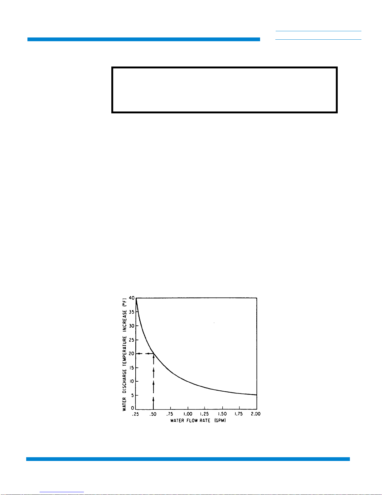
Use the graph in Figure 3-4 to determine the rise in cooling water
temperature as it passes through the compressor. This information is
provided for plant engineering personnel to determine cooling water
requirements.
Find the temperature rise:
1. Draw a vertical line upward from the horizontal axis of the
graph at the water flow rate determined from the previous
section, until it hits the graph curve.
The example shows dashed arrows pointing upward to the graph curve
from 0.50 gpm on the water flow rate axis.
2. At the point which the dashed arrows intersect the graph curve,
draw a straight line to the left to obtain the increase in output water
temperature.
The example shows a temperature increase of 20°F.
Figure 3-4: 8200 Compressor Water Discharge Temperature Increase (°F)

8200 Compressor
P/N 8040353 3-7
C
HELIX TECHNOLOGY CORPORATION
-
TI CRYOGENICS
Final Preparation of Compressor
1. Using a voltmeter, measure the phase-to-phase voltage from the
power source. Compare this voltage to the following table and
position the voltage range selector switch to the “208V” or
“220V” position as required. Also, set the frequency selector
switch to the 50 Hz or 60 Hz position, as appropriate. See
Figure 1-2 for location of selector switches.
2. Ensure that water is turned on for the water-cooled compressor.
3. Set the compressor ON/OFF switch (3) to OFF. Connect the input-
power cable to the power source Refer to Table 1-1, for electrical
power requirements.
4. Turn the compressor switch to the ON position and allow the com-
pressor to run for 15 minutes to stabilize the oil circuit. Make sure
that the compressor fan operates freely in the air-cooled compres-
sor.
5. Switch off the compressor and disconnect the input-power cable.
6. Install the compressor in its permanent location on a level surface.
Air cooled units must have a minimum clearance of 12 inches at the
front and back for adequate airflow.
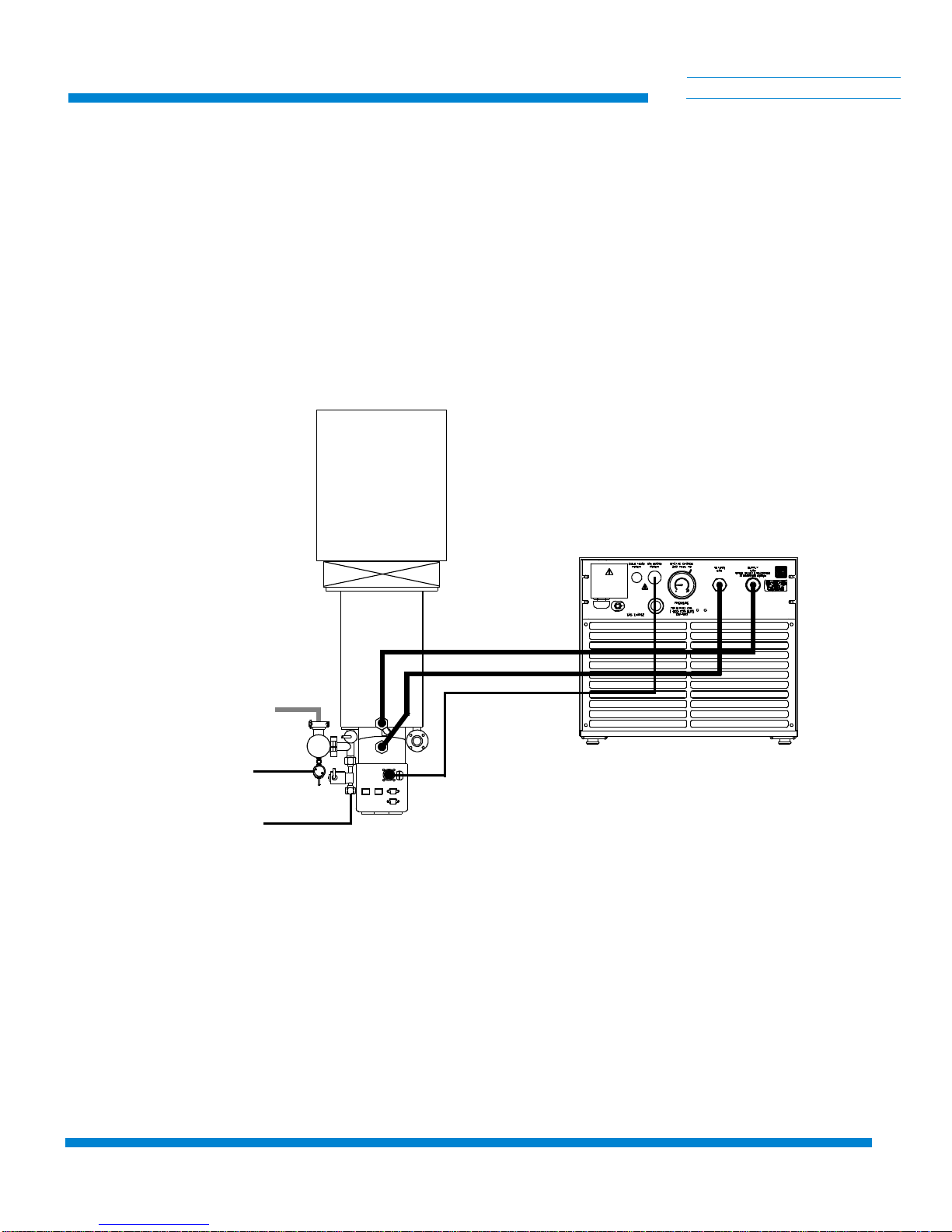
Connecting the Compressor to the Cold Head
Make the connections between the cryopump and compressor. See Figure
3-5.
1. Remove dust plugs and caps from the supply fittings and return
lines, compressor, and cold head. Check all fittings.
2. Connect the helium-gas return line from the gas-return connector
on the rear of the compressor to the gas-return connector on the
cold head.
Table 3-1: Voltage Specifications
Operating Voltage Range
60 Hz 50 Hz
Voltage
AdjustmentSwitch
S1 Position
198-212 180-212 208V
213-250 213-220 220V

Installation
3-8 P/N 8040353
C
HELIX TECHNOLOGY CORPORATION
-
TI CRYOGENICS
3. Connect the helium-gas supply line from the gas-supply connector
on the rear of the compressor to the gas-supply connector on the
cold head.
4. Attach the supply and return line identification decals (CTI-sup-
plied) to their respective connecting piping ends.
5. Verify proper helium supply static pressure by confirming that the
helium pressure gauge reads 245-250 psig (1690-1725 kPa), in an
ambient temperature range of 60 to 100°F (16 to 38°C).
WARNING
Do not operate the 8200 Compressor unless a Cryopump or Waterpump
is connected to the system.
If the indicated pressure is higher than 250 psig (1725 kPa), reduce the
pressure as follows:
a. Remove the flare cap from the gas charge fitting located on
the rear of the compressor.
b. Open the gas charge valve very slowly. Allow a slight
amount of helium gas to escape until the helium pressure
gauge reads 250 psig (1725 kPa).
c. Close the gas charge valve and reinstall the flare cap.
If the indicated pressure is lower than 245 psig (1690 kPa), add helium gas
as described in Adding Helium Gas.
6. Make the following electrical connections.
WARNING
The compressor ON/OFF power switch on the front of the compressor
must be in the OFF position before making any and all electrical connec-
tions.
a. Connect the cold head power cable to the rear panel of the
compressor and the other end to the electrical power con-
nector on the high-vacuum pump cold head.
b. Connect the compressor input power cable to the power
source.
c. Turn on compressor.
d. Your system is now ready for operation.
!
8200 Compressor
P/N 8040353 3-9
C
HELIX TECHNOLOGY CORPORATION
-
TI CRYOGENICS
Figure 3-5: Typical 8200 Compressor Installation
User’s
Vacuum
Chamber
On-Board Power Cable
Helium Return Line
Helium Supply Line
On-Board
Cryopump
Air Pressure (60-80 psi)
Nitrogen (40-80 psi)
Roughing Pump
8200 Compressor
P/N 8040353 4-1
C
HELIX TECHNOLOGY CORPORATION
-
TI CRYOGENICS
Section 4 - Maintenance Procedures
WARNING
Always disconnect the compressor from all sources of electrical power
before performing any maintenance procedures.
Scheduled Maintenance
The only scheduled maintenance required on the 8200 Compressor is
replacement of the compressor adsorber (P/N 8080255K001) every 12
months.
Removing the Compressor Adsorber
1. Shut down the compressor.
2. Disconnect the compressor input power cable from its electrical
power source.
3. Disconnect the flex lines from the gas-return and gas-supply con-
nectors at the rear of the compressor.
4. Remove the screws holding the compressor rear grille, rear panel,
front panel and cover (Figure 1-2). Front and rear panels remain in
place.
5. Use the two wrenches (supplied) to avoid loosening the body of the
coupling from its adapter.
6. Unscrew the two self-sealing coupling halves quickly to minimize
gas leakage as shown in Figure 4-1.
7. Disconnect the adsorber-inlet self-sealing coupling as shown in
Figure 4-1.
8. Remove the bolts, nuts, and washers that secure the adsorber to the
base of the compressor. Save all nuts, bolts, and washers for install-
ing the replacement adsorber.
9. Carefully lift the adsorber inward until the outlet self-sealing cou-
pling clears the rear panel and remove the adsorber as shown in
Figure 4-2.
10. Remove the adsorber from the compressor as shown in Figure 4-2.
Table of contents
Other HELIX Air Compressor manuals


Popular Air Compressor manuals by other brands

tresnar
tresnar GP-FL24 Translation of the original instructions

Campbell Hausfeld
Campbell Hausfeld FP202801 Operating instructions and parts manual

Campbell Hausfeld
Campbell Hausfeld DC01001 Operating instructions and parts manual

CompAir
CompAir D50H RS Operating and service manual

Becker
Becker X 4.25 DV operating instructions

AirMan
AirMan PDS375S-6A1 instruction manual


