HELIX DXP-6 Competition User manual
BEDIENUNGSANLEITUNG
INSTRUCTION MANUAL
deutsch/english
DXP-6 Competition
6-Kanal Digitale Frequenzweiche
6-Channel Digital Crossover

2
Sehr geehrter Kunde,
wir gratulieren Ihnen zum Kauf dieses hochwertigen HELIX-
Produktes. Die digitale 6-Kanal-Frequenzweiche HELIX DXP-6
wurde von uns nach neuesten technischen Erkenntnissen im
Bereich der Digitaltechnik entwickelt und zeichnet sich durch her-
vorragende Verarbeitung und eine überzeugende Anwendung
ausgereifter Technologien aus. Nach mehr als 28 Jahren Erfahrung
in der Forschung und Entwicklung von Audiokomponenten setzen
wir mit der HELIX DXP-6 nun vor allem neue Maßstäbe in
puncto digitaler Signalverarbeitung.
Viel Freude an diesem Produkt wünscht Ihnen das Team von
AUDIOTEC FISCHER
Allgemeines zum Einbau von HELIX-Komponenten
Um alle Möglichkeiten optimal ausschöpfen zu können, lesen Sie
bitte sorgfältig die nachfolgenden Installationshinweise. Wir
garantieren, dass jedes Gerät vor Versand auf seinen einwandfrei-
en Zustand überprüft wurde.
Vor Beginn der Installation unterbrechen Sie den Minusanschluss
der Autobatterie. Wir empfehlen Ihnen, die Installation von einem
Einbauspezialisten vornehmen zu lassen, da der Nachweis eines
fachgerechten Einbaus und Anschlusses des Gerätes
Voraussetzung für die Garantieleistungen sind.
Installieren Sie Ihren HELIX DXP-6 an einer trockenen Stelle im
Auto und vergewissern Sie sich, dass die Frequenzweiche am
Montageort genügend Kühlung erhält. Montieren Sie das Gerät
nicht in zu kleine, abgeschlossene Gehäuse ohne Luftzirkulation
oder in der Nähe von wärmeabstrahlenden Teilen oder elektroni-
schen Steuerungen des Fahrzeuges.
Im Sinne der Unfallsicherheit muß die Frequenzweiche professio-
nell befestigt werden. Dieses geschieht über die beiliegenden
Schrauben, die in eine Montagefläche eingeschraubt werden, die
genügend Halt bieten muss. Bevor Sie die Schrauben im
Montagefeld befestigen, vergewissern Sie sich, daß keine elektri-
schen Kabel und Komponenten, hydraulische Bremsleitungen, der
Benzintank etc. dahinter verborgen sind. Diese könnten sonst
beschädigt werden. Achten Sie darauf, daß solche Teile sich auch
in der doppelten Wandverkleidung verbergen können.
Allgemeines zum Anschluss der Frequenzweiche
Die Frequenzweiche darf nur in Kraftfahrzeuge eingebaut werden,
die den 12V-Minuspol an Masse haben. Bei anderen Systemen
kann der HELIX DXP-6 und die elektrische Anlage
des Kfz beschädigt werden.
Die Plusleitung für die gesamte Anlage sollte in einem Abstand
von max. 30 cm von der Batterie mit einer Hauptsicherung abge-
sichert werden. Der Wert der Sicherung errechnet sich aus der
maximalen Stromaufnahme der Car-Hifi-Anlage. Die
Kabelverbindungen müssen so verlegt sein, dass keine Klemm-,
Quetsch- oder Bruchgefahr besteht. Bei scharfen Kanten
(Blechdurchführungen) müssen alle Kabel gegen Durchscheuern
gepolstert sein. Ferner dürfen die Stromversorgungskabel niemals
mit Zuleitungen zu Vorrichtungen des Kfz (Lüftermotoren,
Brandkontrollmodulen, Benzinleitungen etc.) verlegt werden.
Um eine sichere Installation zu gewährleisten, sollte auf hohe
Qualität der verwendeten Anschlussmaterialien geachtet werden.
deutsch
1
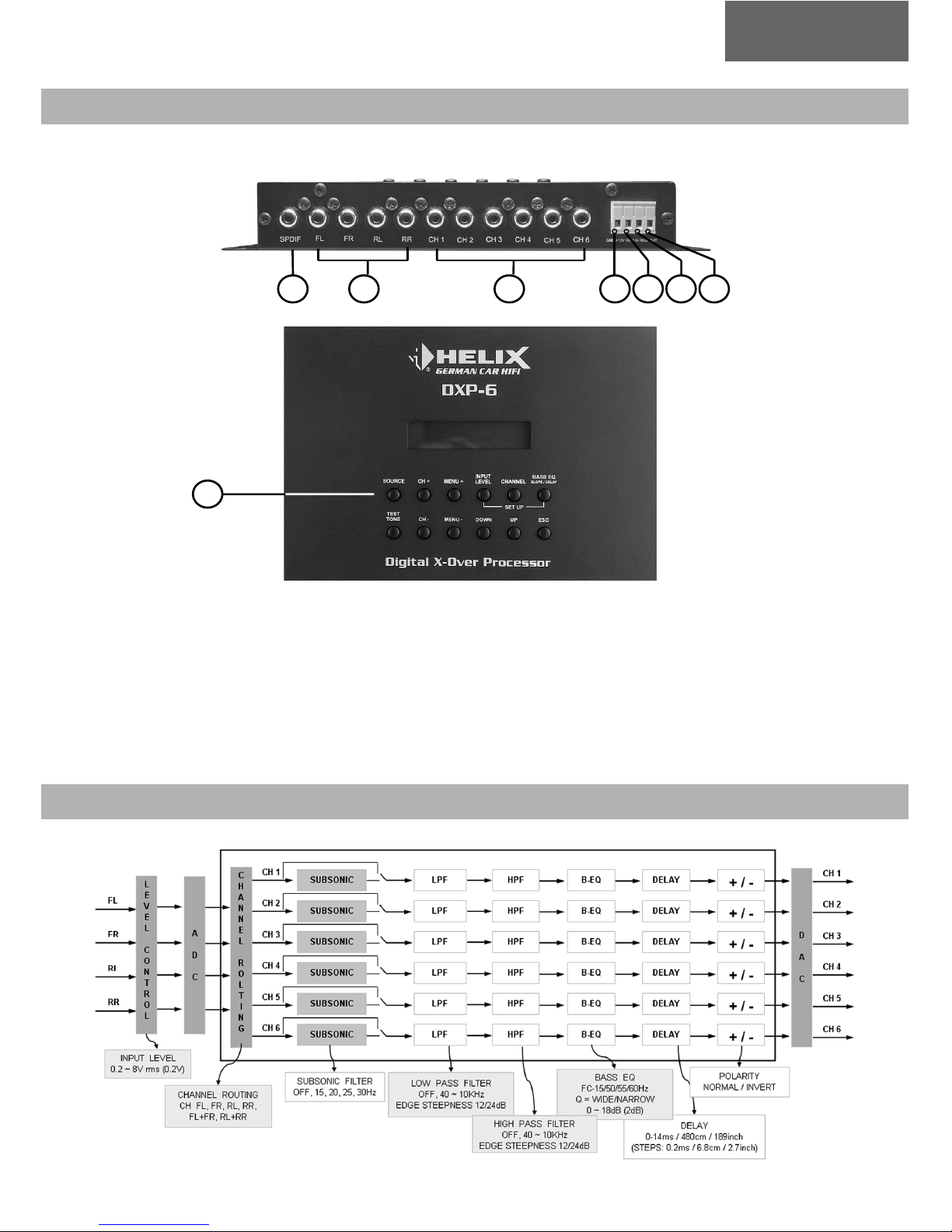
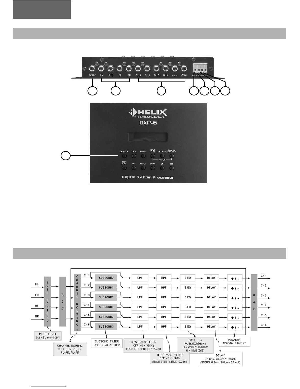
Digitaler Signal-Eingang
Analoger Signal-Eingang
Signal-Ausgang, Kanal 1-6
Power Connector: Massekabel
1
2
3
4
AUSSTATTUNG UND BEDIENELEMENTE HELIX DXP-6
5
6
7
8
Power Connector: +12 Volt
Power Connector: Remote Eingang
Power Connector: Remote Ausgang
Bedieneinheit
FUNKTIONALES BLOCK-DIAGRAMM
3
234567
8
deutsch
Anschluss
1.1 Digitaler Signal-Eingang
Der HELIX DXP-6 verfügt über einen digitalen Signal-Eingang,
der mit dem Vorverstärkerausgang des Steuergerätes verbunden
wird.
2.1 Analoger Signal-Eingang
Der HELIX DXP-6 hat 4 RCA-Anschlüsse zum kontaktieren von
Cinch-Kabeln für 2 Stereosignale, die mit den Vorverstärker-
ausgängen des Steuergerätes verbunden werden.
3.1 Signal-Ausgang, Kanal 1-6
Die Signal-Ausgänge haben RCA-Anschlüsse, die mit den
Eingängen der nachgeschalteten Endstufen verbunden werden.
4.1 Power Connector: Massekabel
Das Massekabel sollte an einem blanken, von Lack
resten befreiten
Massepunkt
des Kfz-Chassis angeschlossen werden.
5.1Power Connector: + 12 Volt
Das +12V-Versorgungskabel ist am Plus der Batterie anzuschlie-
ßen.
6.1Power Connector: Remote-Eingang
Die Remoteleitung wird mit dem automatischen Antennen-
anschluss des Steuergerätes (Radio) verbunden. Dieser ist nur
aktiviert, wenn das Steuergerät EINgeschaltet ist. Somit
wird der
HELIX DXP-6 mit dem Steuergerät ein-und ausgeschaltet.
7.1Power Connector: Remote-Ausgang
Der Remote-Ausgang muss mit dem Remote-Eingang der nachge-
schalteten Endstufen verbunden werden, da sonst Störgeräusche
beim Ein- und Ausschalten der Endstufen entstehen können.
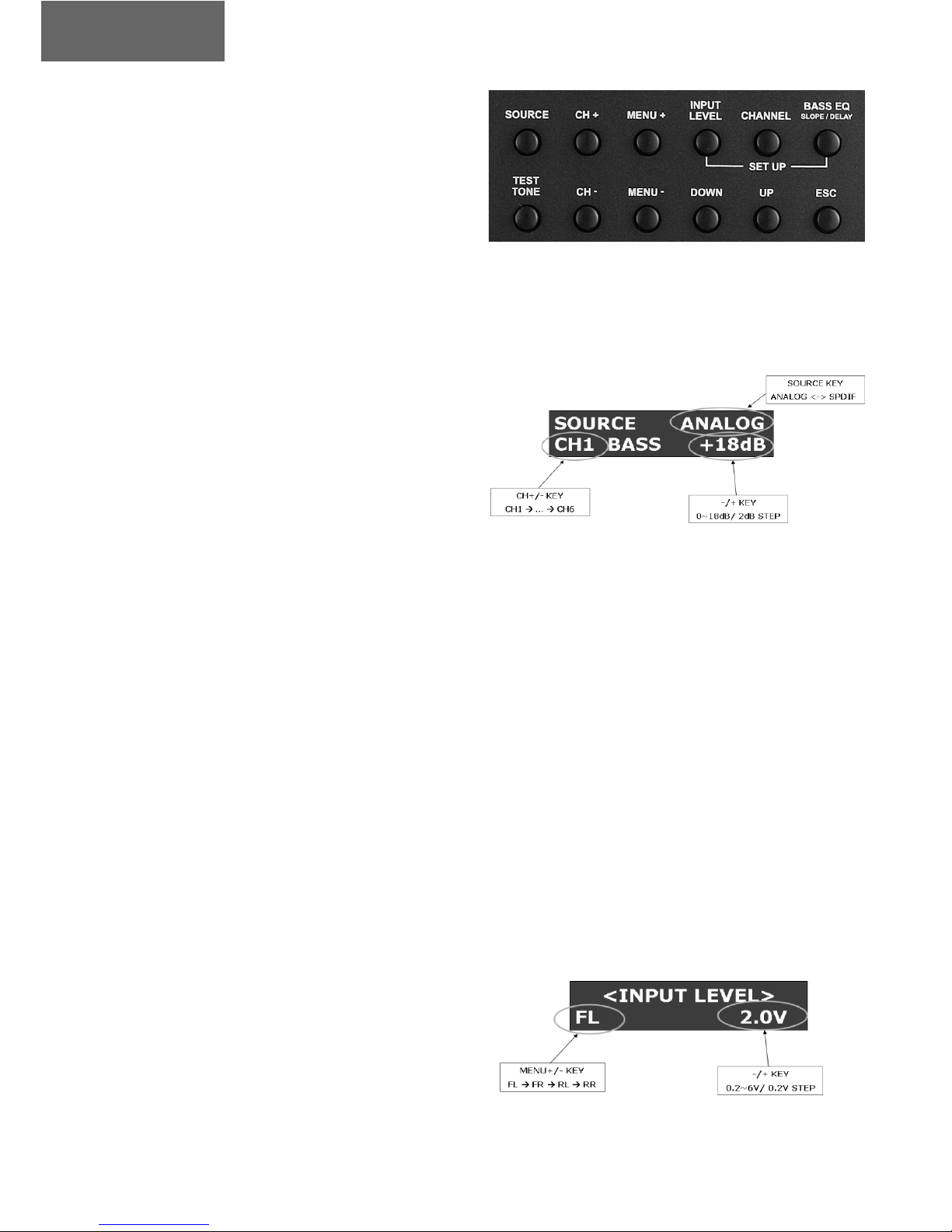
Bedienung
8.1Bedieneinheit
Mit der Bedieneinheit kann die Frequenzweiche eingestellt wer-
den. Der HELIX DXP-6 verfügt über drei verschiedenen
Betriebsarten:
- NORMAL MODE / Normal-Modus
- SETUP MODE / Setupl-Modus
- TEST TONE MODE / Test-Ton-Modus
8.1.1 Normal Mode / Normal-Modus
Der Normalmodus startet, nachdem der HELIX DXP-6 über das
Remote-Eingangssignal eingeschaltet wurde. Im Normalmodus
kann die Eingangsquelle (analog / digital) ausgewählt und der
Basspegel für die Ausgangskanäle 1-6 eingestellt werden.
8.1.1 Auswahl der Eingangsquelle
Über die SOURCE-Taste kann eingestellt werden ob der
Digitaleingang oder die Analog-Eingänge genutzt werden sollen.
8.1.2 Einstellen der Basspegel
Mit den Tasten UP und DOWN wird der Bassboost in 2-dB-
Schritten von 0 bis 18 dB eingestellt. Der einzustellende
Ausgangskanal wird über die Tasten CH+ und CH–ausgewählt.
8.2.1Setup Mode / Setup-Modus
Im Setup-Modus können die folgenden Einstellungen vorgenom-
men werden:
- INPUT LEVEL SETUP / Einstellung Eingangspegel (nur analog)
- CHANNEL SETUP / Kanal-Einstellung
- BASS EQ SETUP / Bass-Equalizer-Setup
8.2.1 Input Level Setup / Einstellung Eingangspegel
Durch Betätigung der Taste INPUT LEVEL wird das entsprechen-
de Menü aufgerufen. Mit den Tasten UP und DOWN wird der
Eingangspegel eingestellt.
4
deutsch
Der einzustellende Eingangskanal wird über die Tasten MENU+
und MENU–ausgewählt.
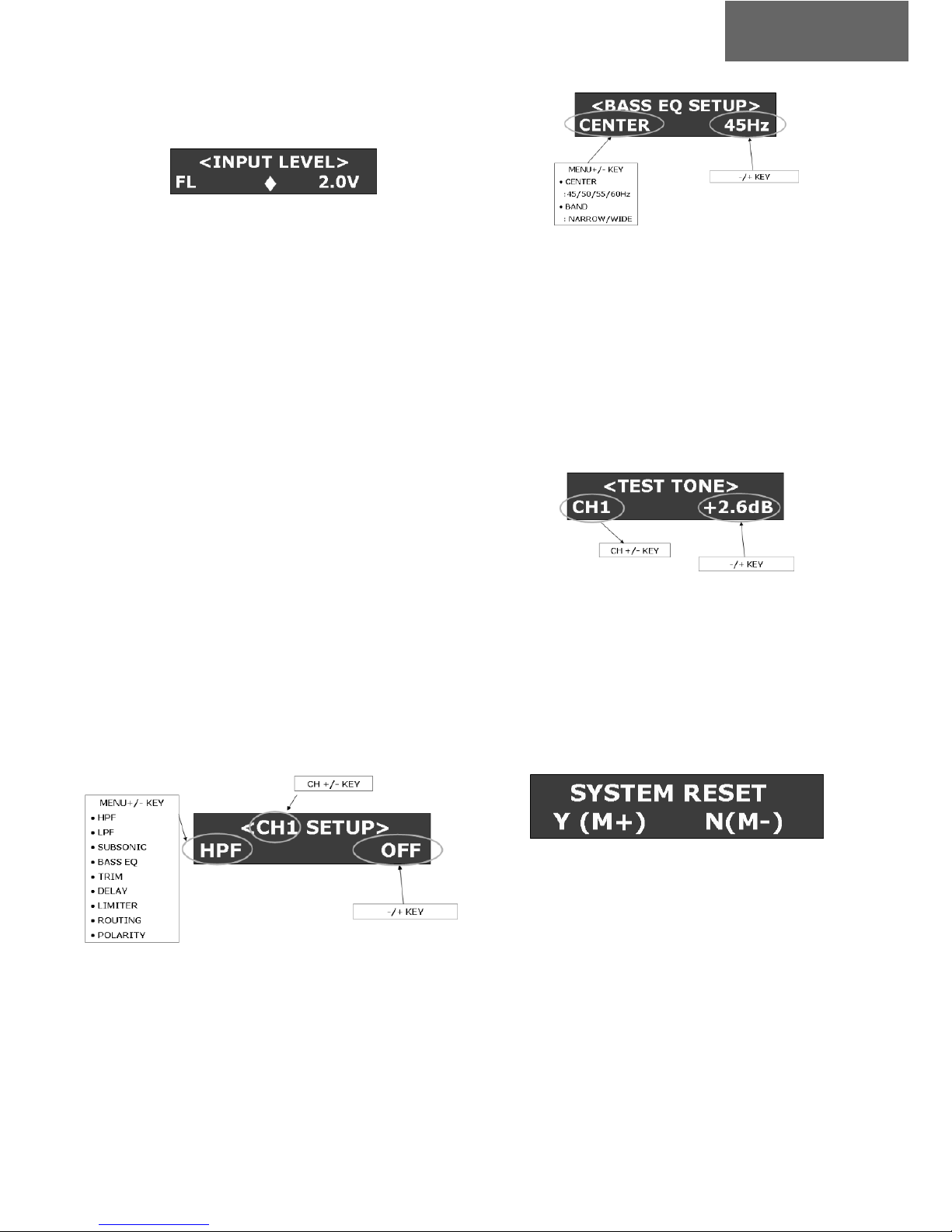
Sollte sich das Eingangs-Signal im Bereich des Clipping befinden,
erscheint im Display ein ausgefüllter HELIX-Diamant. Andernfalls
ist der Diamant nicht ausgefüllt.
8.2.2 Channel-Setup / Kanal-Einstellung
Durch Betätigung der Taste CHANNEL wird das entsprechende
Menü aufgerufen. Mit den Tasten CH+ und CH–lassen sich die
einzustellenden Ausgangskanäle auswählen. Mit den Tasten
MENU+ und MENU– wird die für den Kanal einzustellende
Funktion ausgewählt. Die entsprechenden Einstellungen lassen
sich über die Tasten UP und DOWN vornehmen.
Im Menü DELAY TIME lässt sich über die Taste BASS EQ/
SLOPE/ DELAY zwischen den Einheit ms / cm / inch umschalten.
Bei den Filtereinstellungen dient die Taste BASS EQ/ SLOPE/
DELAY zur Einstellung der Flankensteilheit 12 oder 24dB.
- HPF........................... 40 Hz - 10 kHz
- LPF............................40 Hz - 10 kHz
- Subsonic Filter..........15 Hz - 30 Hz
- Bass EQ Level........... 0 dB - 18 dB
- Channel Trim Level...-6 dB - + 6dB
- Delay Time................0 - 14 ms / 480 cm / 189 inch
- Channel Routing.......FL > FR > RL > RR > FL
and FR mix > RL and RR mix
- Polarität................... Normal > Invert
8.2.3 Bass-EQ-Setup / Bass-Equalizer-Setup
Durch Betätigung der Taste BASS EQ wird das entsprechende
Menü aufgerufen. Mit den Tasten MENU+ und MENU– wird die
einzustellende Funktion ausgewählt. Die entsprechenden
Einstellungen lassen sich über die Tasten UP und DOWN vorneh-
men.
- Center Frequency......... 45 Hz - 60 Hz
- Bandwith..................... Narrow > Wide
8.3 Test Tone Mode / Test Ton-Modus
Der HELIX DXP-6 verfügt über einen Test-Ton-Modus (weißes
Rauschen), um die Lautsprecheranschlüsse und die Balance-
Einstellungen der Kanäle zu testen. Um in den Modus zu gelan-
gen, ist die Taste TEST-TONE Taste zu betätigen.
Der zu testende Kanal wird über die Tasten CH+ und CH– ausge-
wählt. Mit den Tasten UP und DOWN kann der Test-Ton-Pegel
eingestellt werden. Um den Test-Ton-Modus zu verlassen, ist die
Taste ESC oder die Taste TEST TONE zu betätigen.
9 Werkseinstellung
Um den HELIX DXP-6 auf die Werkseinstellung zurückzusetz-
ten, ist die ESC 5 Sekunden lang zu betätigen. Zum Bestätigen
des Reset-Vorgangs ist die Taste MENU+ (entspricht Y=yes) zu
betätigen. Mit der Taste MENU– (entspricht N=no) oder ESC wird
der Vorgang abgebrochen.
5
deutsch

Helix Produkte geniessen aufgrund ihres hohen Qualitätsniveaus inter-
national einen ausgezeichneten Ruf. Daher gewähren wir eine
Garantiezeit von 2 Jahren.
Die Produkte werden während der gesamten Fertigung ständig kon-
trolliert und geprüft. Bitte beachten Sie im Servicefall folgende
Hinweise:
1. Die 2-jährige Garantiezeit beginnt mit Kauf des Produktes
und gilt nur für den Erstbesitzer.
2.
Während der Garantiezeit beseitigen wir etwaige Mängel,
die
nachweislich auf Material- oder Fabrikationsfehlern beru-
hen, nach unserer Wahl durch Austausch oder Nach-
besserung der defekten Teile. Weitergehende Ansprüche,
insbesondere auf Minderung, Wandlung, Schadenersatz oder
Folgeschäden sind ausgeschlossen. Ersetzte Teile gehen in
das Eigentum von Audiotec Fischer über. Die Garantiezeit wird
von einer Garantieleistung durch uns nicht berührt.
3. Am Produkt dürfen keine unsachgemäßen Eingriffe vorge-
nommen worden sein.
4. Bei Inanspruchnahme der Garantie wenden Sie sich bitte
zuerst an Ihren Fachhändler. Sollte es notwendig sein, das
Produkt an uns einzuschicken, so beachten Sie bitte folgen-
de Hinweise:
a) Das Produkt muss in einwandfreier Originalverpackung
verschickt werden.
b)
Die Garantiekarte muss ausgefüllt dem Produkt beiligen.
c) Das Produkt muss frachtfrei zugestellt werden, d. h.
Porto und Risiko gehen zu Ihren Lasten
d) Die Kaufquittung muss beiliegen.
5. Von der Garantie ausgenommen sind:
a) Transportschäden, sichtbar oder unsichtbar (Reklama-
tionen für solche Schäden müssen umgehend bei der
Transportfirma eingereicht werden)
b) Kratzer in Metallteilen, Frontabdeckungen usw. Diese
Defekte müssen innerhalb von 5 Tagen nach Kauf direkt
bei Ihrem Händler reklamiert werden.
c) Fehler, die durch fehlerhafte Aufstellung, falschen
An-
schluss, unsachgemäße Bedienung, Beanspruchung
oder
äußere gewaltsame Einwirkung entstanden sind.
d) Unsachgemäß reparierte oder geänderte Geräte, die von
anderer Seite als von uns geöffnet wurden.
e) Folgeschäden an fremden Geräten
f) Kostenerstattung bei Schadensbehebung durch Dritte
ohne unser vorheriges Einverständnis
g) Geräte mit entfernten Typenschildern oder Seriennummern.
TECHNISCHE DATEN HELIX DXP-6
Tiefpass . . . . . . . . . . . . . . . . . . . . . . . . . . . . . . . . . . . . . . . . . . . . . . . . . . . . . . . . . . . . . . . . . . . 40 Hz - 10 kHz
Hochpass . . . . . . . . . . . . . . . . . . . . . . . . . . . . . . . . . . . . . . . . . . . . . . . . . . . . . . . . . . . . . . . . . . 40 Hz - 10 kHz
Subsonic Filter . . . . . . . . . . . . . . . . . . . . . . . . . . . . . . . . . . . . . . . . . . . . . . . . . . . . . . . . . . . . . . . 15 Hz - 30 Hz
Bass Boost Pegelanhebung . . . . . . . . . . . . . . . . . . . . . . . . . . . . . . . . . . . . . . . . . . . . . . . . . . . . . . . 0 dB - 18 dB
Bass Boost Mittenfrequenz . . . . . . . . . . . . . . . . . . . . . . . . . . . . . . . . . . . . . . . . . . . . . . . . . . . . . . 45 Hz - 60 Hz
Phase . . . . . . . . . . . . . . . . . . . . . . . . . . . . . . . . . . . . . . . . . . . . . . . . . . . . . . . . . . . . . . . . . . . . . . . . 0° / 180°
Flankensteilheit . . . . . . . . . . . . . . . . . . . . . . . . . . . . . . . . . . . . . . . . . . . . . . . . . . . . . . . . . . . . . . 12 dB / 24 dB
Lautzeitverzögerung . . . . . . . . . . . . . . . . . . . . . . . . . . . . . . . . . . . . . . . . . . . . . . 0 - 14 ms / 480 cm / 189 inch
Klirrfaktor Analog-Input (THD+N) . . . . . . . . . . . . . . . . . . . . . . . . . . . . . . . . . . . . . . . . . . . . . . . . . . . . . < 0,01%
Klirrfaktor Digital-Input (THD+N) . . . . . . . . . . . . . . . . . . . . . . . . . . . . . . . . . . . . . . . . . . . . . . . . . . . . . < 0,005%
Geräuschspannungsabstand Analog-Input . . . . . . . . . . . . . . . . . . . . . . . . . . . . . . . . . . . . . . . . . . . . . . . . > 95 dB
Geräuschspannungsabstand Digital-Input . . . . . . . . . . . . . . . . . . . . . . . . . . . . . . . . . . . . . . . . . . . . . . . > 100 dB
Eingangsimpedanz . . . . . . . . . . . . . . . . . . . . . . . . . . . . . . . . . . . . . . . . . . . . . . . . . . . . . . . . . . . . . . . . 10 kOhm
Ausgangsimpedanz . . . . . . . . . . . . . . . . . . . . . . . . . . . . . . . . . . . . . . . . . . . . . . . . . . . . . . . . . . . . . . . . 10 kOhm
Eingangsempfindlichkeit . . . . . . . . . . . . . . . . . . . . . . . . . . . . . . . . . . . . . . . . . . . . . . . . . . . . . . . . . . . 0,2 V - 8 V
Ausgangspegel . . . . . . . . . . . . . . . . . . . . . . . . . . . . . . . . . . . . . . . . . . . . . . . . . . . . . . . . . . . . . . . . . . . max. 4 V
SPDIF-Eingangspegel . . . . . . . . . . . . . . . . . . . . . . . . . . . . . . . . . . . . . . . . . . . . . . . . . . . . . . . . . . . . . . . 200 mV
Sicherung . . . . . . . . . . . . . . . . . . . . . . . . . . . . . . . . . . . . . . . . . . . . . . . . . . . . . . . . . . . . . . . . . . . . . . .3 Ampere
Abmessungen (H x B x T) in mm . . . . . . . . . . . . . . . . . . . . . . . . . . . . . . . . . . . . . . . . . . . . . . . . . 33 x 235 x 140
Gewicht netto . . . . . . . . . . . . . . . . . . . . . . . . . . . . . . . . . . . . . . . . . . . . . . . . . . . . . . . . . . . . . . . . . . . . . 0,86 kg
GARANTIEBESTIMMUNGEN
6
deutsch

7
Dear Customer,
Congratulations on purchasing this high-quality HELIX-product.
The HELIX DXP-6 highlights best quality, excellent manufactu-
ring and state-of-the-art technology. After 28 years of experience
in the research & development of audio products this crossover
sets new standards concerning digital signal processing.
We wish you many hours of enjoyment with your new digital
HELIX crossover.
Yours
AUDIOTEC FISCHER Team
General installation instructions for HELIX-components
To find out how digital HELIX crossover works best for you, read
this manual carefully and follow the instructions for installation.
We guarantee that this product has been checked for proper
functioning before shipping.
Before you start installation, disconnect the car battery at the
minus pole. We would urge you to have the installation work car-
ried out by a specialist as verification of correct installation and
connection of the unit is a prerequisite for warranty cover of this
HELIX product.
Install your HELIX DXP-6 at a dry location where there is suffi-
cient air circulation to ensure adequate cooling of the equipment.
For safety reasons, the crossover must be secured in a professio-
nal manner. This is performed by means of the fixing screws scre-
wed into a mounting surface offering sufficient retention and sta-
bility.
Before drilling the holes for the screws, carefully examine the area
around the installation position and make sure that there are no
electrical cables or components, hydraulic brake lines or any part
of the petrol tank located behind the mounting surface - otherwi-
se these could be damaged. You should be aware of the fact that
such components may also be concealed in the double-skin trim
panels/mouldings.
General instruction for connecting the digital crossover
The HELIX DXP-6 may only be installed in motor vehicles which
have a 12-volt minus pole connected to the chassis ground. Any
other system could cause damage to the amplifier and the elec-
trical system of the vehicle.
The plus cable from the battery for the complete system should be
provided with a main fuse at a distance of max. 30 cm from the
battery. The value of the fuse is calculated from the maximum total
current input of the car audio system.
Install the cabling in a manner which precludes any danger of the
leads being exposed to shear, crushing or rupture forces. If there are
sharp edges in the vicinity (e.g. holes in the bodywork) all cables
must be cushioned and protected to prevent fraying.
Never lay the power supply cables adjacent to leads and lines
connecting other vehicle equipment (fan motors, fire detection
modules, gas lines etc.).
In order to ensure safe installation, use only high-quality connections
and materials. Ask your dealer for high quality accessories.
english
Digital Signal-Input
Analog Signal-Input
Signal-Output, Channel 1-6
Power Connector: Ground
1
2
3
4
5
6
7
8
Power Connector: +12 Volt
Power Connector: Remote Input
Power Connector: Remote Output
Control Unit
8
english
1
EQUIPMENT AND CONTROL UNIT OF THE HELIX DXP-6
234567
8
FUNCTIONAL BLOCK-DIAGRAM

Connection
1.1 Digital Signal-Input
The HELIX DXP-6 has a Digital Signal-Input which has to be
connected to the pre-amplifier-output of the head-unit.
2.1 Analog Signal-Input
The HELIX DXP-6 offers 4 RCA-connectors which generate 2
Stereo-Signals. Thus, the HELIX DXP-6 can be connected to the
pre-amlifier-output of the head-unit by using Cinch-plugs.
3.1 Signal-Output, Channel 1-6
The Signal-Outputs have RCA-connectors which are connected to
the input of the downstream amplifier.
4.1 Power Connector: Ground Cable
The Ground Cable should be connected to a to a dismantled, unla-
quered ground point of the car chassis.
5.1Power Connector: + 12 Volt
The +12V-Cable has to be connected to a positive pole.
6.1Power Connector: Remote-Input
The Remote-Input has to be connected to the remote output of
the head-unit. It is only active if the head-unit in ON. Thus, the
HELIX DXP-6 is switched on and off automatically togehter with the
head-unit.
7.1Power Connector: Remote-Output
The Remote-Output has to be connected to the Remote-Input of
the downstream amplifiers. If this is neglected, static noise can
occur when the amplifiers are switched on or off.
Operation
8.1Control Unit
Via the Control Unit the Digital Crossover HELIX DXP-6 can be
operated in three different control modes:
- NORMAL MODE
- SETUP MODE
- TEST TONE MODE
8.1.1 Normal Mode
The Normal Mode starts after the HELIX DXP-6 has been swit-
ched on via the Remote-Input-Signal. The Input-Source (analog/
digital) can be chosen in the Normal Mode. Moreover, the Bass
Level for the Output-Channels 1-6 can be adjusted.
8.1.1 Selection of the Input-Source
Using the SOURCE-key, either the analog or the digital input
mode can be chosen.
8.1.2 Adjustment of the Bass Level
Using the keys UP and DOWN the Bass Level can be adjusted in
2-dB-steps from 0 to 18 dB. The respective Output-Channel can
be chosen via the keys CH+ und CH–.
8.2.1Setup Mode
The following adjustments can carried out in the Setup-Mode:
- INPUT LEVEL SETUP (only analog)
- CHANNEL SETUP
- BASS EQ SETUP
8.2.1 Input Level Setup
Using the key INPUT LEVEL the respective menu can be chosen.
Via the keys UP and DOWN the Input Level can be adjusted.
9
english

The respective channel has to be chosen with the keys MENU+
und MENU–.
If the Input Signal is in the clipping area, the display will show a
filled-out HELIX diamond. If there is no clipping, the HELIX dia-
mond is not filled out.
8.2.2 Channel-Setup
By using the the CHANNEL key, the respective menu can be selec-
ted. The output channels which have to be adjusted can be selec-
ted via the keys CH+ and CH–. Please chose the desired function
for each channel with the keys MENU+ and MENU–. The respec-
tive settings can be made with the keys UP and DOWN.
The menu DELAY TIME provides the possibility to change the
displayed unit. Use the key BASS EQ/ SLOPE/ DELAY to select
between ms / cm / inch. Use the key BASS EQ/ SLOPE/ DELAY
for the filter settings. The edge steepness can be adjusted bet-
ween 12 or 24dB.
- HPF........................... 40 Hz - 10 kHz
- LPF............................40 Hz - 10 kHz
- Subsonic Filter..........15 Hz - 30 Hz
- Bass EQ Level........... 0 dB - 18 dB
- Channel Trim Level...-6 dB - + 6dB
- Delay Time................0 - 14 ms / 480 cm / 189 inch
- Channel Routing.......FL > FR > RL > RR > FL
and FR mix > RL and RR mix
- Polarity..................... Normal > Invert
8.2.3 Bass-EQ-Setup / Bass-Equalizer-Setup
By using the key BASS EQ, the respective menu can be chosen.
Select the desired function with the keys MENU+ and MENU–. The
settings can be made via the keys UP and DOWN.
- Center Frequency......... 45 Hz - 60 Hz
- Bandwith..................... Narrow > Wide
8.3 Test Tone Mode
The HELIX DXP-6 has a Test-Tone-Mode (white noise) in order
to test the loudspeaker connections and the balance settings of
each channel. Use the key TEST TONE to select the mode.
The channel which shall be tested can be selected via the keys
CH+ and CH–. Use the keys UP and DOWN to adjust the test-
tone-level. Use the keys ESC or TEST TONE to quit the Test-Tone-
Mode.
9 Default Settings
in order the restore the default settings of HELIX DXP-6, press
the ESC key for 5 seconds. Confirm the reset process with the
key MENU+ (=Y=yes). Press the key MENU– (=N=no) or ESC to
cancel the reset process.
10
english

Due to the high quality standard Helix products achieved an excellent
international reputation. Therefore we grant a warranty period of 2
years. The products are checked and tested carefully during the enti-
re production process. In the case of service note the following:
1) The 2 years warranty period commences with the purchase of
the product and is applicable only to the original owner.
2) During the warranty period we will rectify any defects
due to faulty material or workmanship by replacing or repai-
ring the defective part at our decision.
Further claims, and in particular those for price reduction,
cancellation of sale, compensation for damages or subse
quential damages, are excluded. The warranty period is not
altered by the fact that we have carried out warranty work.
3) Unauthorized tampering with the product will invalidate this
warranty.
4) Consult your authorized dealer first, if warranty service is
needed. Should it be necessary to return the product to the
factory, please ensure that
a) the product is packed in original factory packing in
good condition
b) the warranty card has been filled out and attached to the
product
c) the product is shipped prepaid, i.e. at your expense
and risk
d) the receipt/invoice as proof of purchase is enclosed
5) Excluded from the warranty are:
a) Shipping damages, either readily apparent or concea-
led (claims for such damages must be immediately
notified to the forwarding agent).
b) Scratches in metal parts, front panels or covers etc.
This must be notified to your dealer within 5 days of purchase.
c) Defects caused by incorrect installation or connec-
tion, by operation errors, by overloading or by external force.
d) Products which have been repaired incorrectly or
modified or where the product has been opened by
other persons than us.
e) Consoquential damages to other equipments.
f) Reimbursement when repairing damages by third
parties without our previous permission
g) Products with removed serial numbers
TECHNICAL DATA HELIX DXP-6
Lowpass . . . . . . . . . . . . . . . . . . . . . . . . . . . . . . . . . . . . . . . . . . . . . . . . . . . . . . . . . . . . . . . . . . . 40 Hz - 10 kHz
Highpass . . . . . . . . . . . . . . . . . . . . . . . . . . . . . . . . . . . . . . . . . . . . . . . . . . . . . . . . . . . . . . . . . . 40 Hz - 10 kHz
Subsonic Filter . . . . . . . . . . . . . . . . . . . . . . . . . . . . . . . . . . . . . . . . . . . . . . . . . . . . . . . . . . . . . . . 15 Hz - 30 Hz
Bass Boost Level Increase . . . . . . . . . . . . . . . . . . . . . . . . . . . . . . . . . . . . . . . . . . . . . . . . . . . . . . . . 0 dB - 18 dB
Bass Boost Center Frequency . . . . . . . . . . . . . . . . . . . . . . . . . . . . . . . . . . . . . . . . . . . . . . . . . . . . 45 Hz - 60 Hz
Phase . . . . . . . . . . . . . . . . . . . . . . . . . . . . . . . . . . . . . . . . . . . . . . . . . . . . . . . . . . . . . . . . . . . . . . . . 0° / 180°
Edge Steepness . . . . . . . . . . . . . . . . . . . . . . . . . . . . . . . . . . . . . . . . . . . . . . . . . . . . . . . . . . . . . 12 dB / 24 dB
Time Delay . . . . . . . . . . . . . . . . . . . . . . . . . . . . . . . . . . . . . . . . . . . . . . . . . . . . 0 - 14 ms / 480 cm / 189 inch
Total Harmonic Distortion Analog-Input (THD+N) . . . . . . . . . . . . . . . . . . . . . . . . . . . . . . . . . . . . . . . . . . < 0,01%
Total Harmonic Distortion Digital-Input (THD+N) . . . . . . . . . . . . . . . . . . . . . . . . . . . . . . . . . . . . . . . . . . < 0,005%
Signal-To-Noise-Ratio Analog-Input . . . . . . . . . . . . . . . . . . . . . . . . . . . . . . . . . . . . . . . . . . . . . . . . . . . . . > 95 dB
Signal-To-Noise-Ratio Digital-Input . . . . . . . . . . . . . . . . . . . . . . . . . . . . . . . . . . . . . . . . . . . . . . . . . . . . > 100 dB
Input-Impedance . . . . . . . . . . . . . . . . . . . . . . . . . . . . . . . . . . . . . . . . . . . . . . . . . . . . . . . . . . . . . . . . . 10 kOhm
Output-Impedance . . . . . . . . . . . . . . . . . . . . . . . . . . . . . . . . . . . . . . . . . . . . . . . . . . . . . . . . . . . . . . . . 10 kOhm
Input Sensivity . . . . . . . . . . . . . . . . . . . . . . . . . . . . . . . . . . . . . . . . . . . . . . . . . . . . . . . . . . . . . . . . . 0.2 V - 8 V
Output-Level . . . . . . . . . . . . . . . . . . . . . . . . . . . . . . . . . . . . . . . . . . . . . . . . . . . . . . . . . . . . . . . . . . . . max. 4 V
SPDIF-Input-Level . . . . . . . . . . . . . . . . . . . . . . . . . . . . . . . . . . . . . . . . . . . . . . . . . . . . . . . . . . . . . . . . . 200 mV
Fuse . . . . . . . . . . . . . . . . . . . . . . . . . . . . . . . . . . . . . . . . . . . . . . . . . . . . . . . . . . . . . . . . . . . . . . . . . .3 Ampere
Dimensions (H x W x D) in mm . . . . . . . . . . . . . . . . . . . . . . . . . . . . . . . . . . . . . . . . . . . . . . . . . . 33 x 235 x 140
Weight net . . . . . . . . . . . . . . . . . . . . . . . . . . . . . . . . . . . . . . . . . . . . . . . . . . . . . . . . . . . . . . . . . . . . . . . 0.86 kg
WARRANTY REGULATIONS
11
english

Audiotec Fischer GmbH
Huenegraeben 26
D-57392 Schmallenberg
Tel.: +49 2972 97880
Fax: +49 2972 978888
www.audiotec-fischer.com
helix@audiotec-fischer.com
Table of contents
Languages:
Other HELIX Crossover manuals


