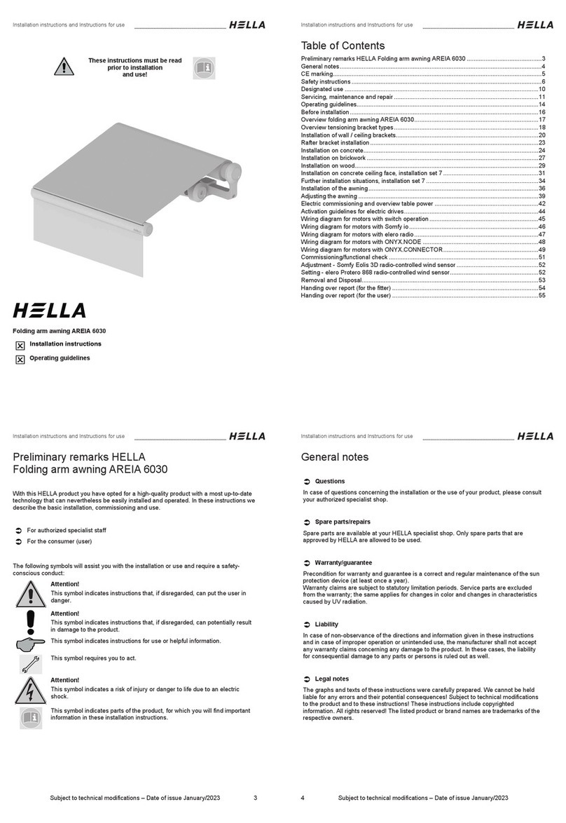
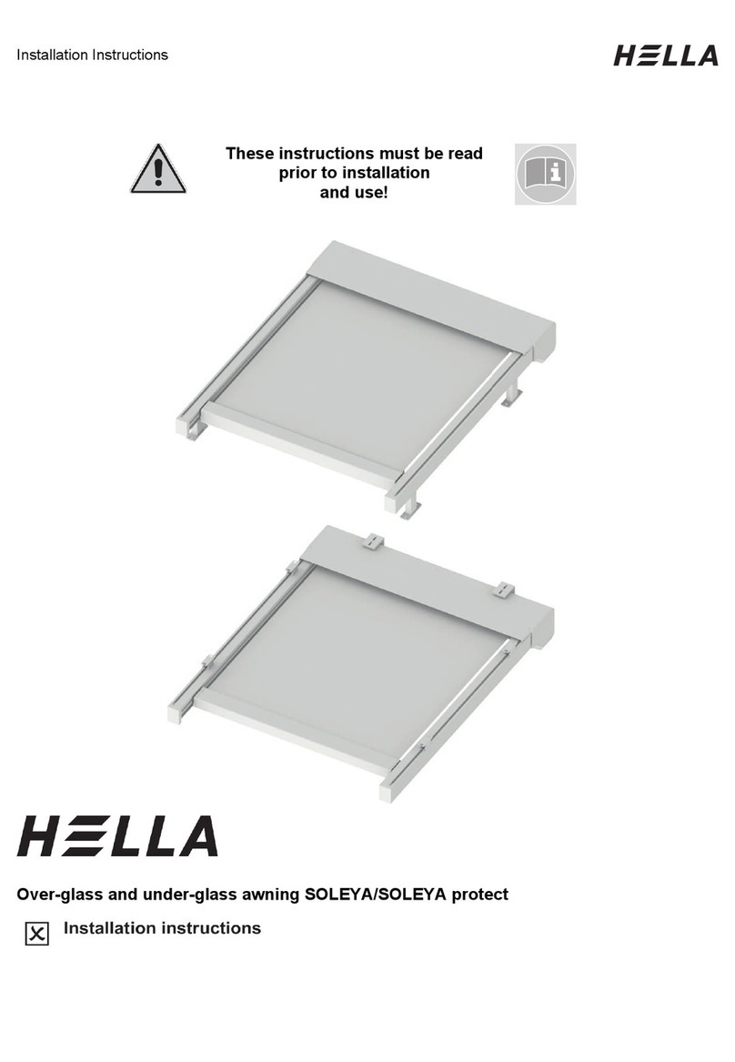
Hella Pergola VENTUR User manual

Installation Instructions
These instructions must be read
prior to installation
and use!
VENTUR Pergola

Installation Instructions
Table of Contents
Preliminary remarks HELLA VENTUR Pergola ....................................................................3
Before installation.................................................................................................................4
Designs of the basic modules...............................................................................................5
Exploded view ......................................................................................................................7
Marking and fixing the floor brackets..................................................................................13
Marking and fixing the wall brackets...................................................................................22
Marking and fixing the wall brackets Type self-supporting to wall .....................................27
Mounting base....................................................................................................................30
Preparing the columns........................................................................................................35
Installation self-supporting..................................................................................................36
Column flush with the wall with VENTUR self-supporting...................................................42
Wall installation ..................................................................................................................44
Wall mounting VENTUR Free.............................................................................................49
Installation of corner joints for the LED corner cover profile ...............................................51
Sealing of rain gutter ..........................................................................................................52
Installation with corner joint ................................................................................................56
Mounting the covering profiles............................................................................................57
Installation of the basic profile units....................................................................................59
Electric plug-in connections................................................................................................62
Electric supply line..............................................................................................................64
Installation of the slats........................................................................................................66
Adjusting the rain gutters....................................................................................................70
Mounting the intermediate column .....................................................................................72
Mounting the snap-on bracket for VENTUR SIDE..............................................................76
Mounting the intermediate column .....................................................................................79
Mounting an additional column flush with the wall..............................................................82
Installation of the VENTUR SIDE .......................................................................................84
Electric plug-in connections................................................................................................91
Troubleshooting VENTUR SIDE.........................................................................................96
Installation of the box top boards........................................................................................97
Mounting the column sealing sheets ................................................................................101
Installation of the wall connection cover sheet .................................................................104
Preparing the wall connection over sheet.........................................................................105
Inspection panel for electronic components .....................................................................127
Mounting rain and wind sensor ONYX..............................................................................128
Electrical data...................................................................................................................129
Wiring diagram for the motors ..........................................................................................130
Wiring diagram for the LED lighting..................................................................................131
Operation and configuration Pergola PLUS with ONYX ..................................................132
Commissioning/functional check ......................................................................................141
Removal ...........................................................................................................................142

Installation Instructions
Subject to technical modifications – Date of Issue
September/2023
3
Preliminary remarks HELLA
VENTUR Pergola
With this HELLA product you have opted for a high-quality product with a most up-to-date
technology that nevertheless can be easily operated. In these instructions we describe the
basic installation, commissioning and use.
For authorized specialist staff
For the consumer (user)
The following symbols will assist you with the installation or use and require a safety-
conscious conduct:
Attention!
This symbol indicates instructions that, if disregarded, can put the user in
danger.
Attention!
This symbol indicates instructions that, if disregarded, can potentially
result in damage to the product.
This symbol indicates
instructions for use or
helpful information.
This symbol requires you to
act.
Attention!
This symbol indicates a risk of injury or danger to life due to an electric
shock.
This symbol indicates parts of the product, for which you will find
important information in these installation instructions.
Attention!
This symbol indicates possible risk of injury by crushing.
This symbol indicates the
cleaning of the product.
This symbol indicates the
maintenance and repair of
the product.

Installation Instructions
4
Subject to technical modifications – Date of Issue
September/2023
Before installation
Check the product immediately for possible shipping damage and for
compliance with the delivery receipt.
If parts are missing or damaged, please consult your supplier immediately.
Check the mounting base and ensure that the mounting material to be used
complies with the given conditions to guarantee proper installation. In case
of doubt, please seek advice from a specialist enterprise for fixing
techniques.
The packaging cardboard box should not be exposed to humidity. To
protect it from rain during transport, it should be covered by a foil.
Carry larger units by two persons. Transport and store the units carefully to
prevent injury of persons and damage to the product.
Remove the packaging material carefully. When using a knife, be careful
not to damage the packaging content and to avoid cuts!
Dispose of the packaging material via recycling.
Caution!
A wrong installation can endanger the user seriously. Please strictly
observe the installation instructions. Close off the place of installation.
When working at higher heights, there is risk of falling. Suitable ascent
supports, scaffoldings and fall protection devices are to be used. Please
make sure that the ascent supports stand solidly and provide a firm grip.

Installation Instructions
Subject to technical modifications – Date of Issue
September/2023
5
Designs of the basic modules
It is possible to turn and combine the modules just as you like. Installation to the wall:
Depending on the side the VENTUR is positioned to the wall, the running direction of the
slats changes accordingly.
VENTUR self-supporting VENTUR Additional module
at the front
VENTUR Additional module
lateral
VENTUR Wall installation
Side V or H
VENTUR Wall installation
Additional module at the front
VENTUR Wall installation
Additional side module
VENTUR Wall installation
Side L or R
VENTUR Wall installation
Additional side module
VENTUR Wall installation
Additional module at the
front

Installation Instructions
6
Subject to technical modifications – Date of Issue
September/2023
Designs of the basic modules
It is possible to turn and combine the modules just as you like. Installation to the wall:
Depending on the side the VENTUR is positioned to the wall, the running direction of the
slats changes accordingly.
VENTUR Free
Side V or H
VENTUR Free
Additional side module
VENTUR Free
Side L or R
VENTUR Free
Additional module at the
front

Installation Instructions
Subject to technical modifications – Date of Issue
September/2023
7
Exploded view
VENTUR self-supporting
45°
0°
A
B
C
D
H
R
V
L
1
11
11
2
3
3
2
11
2
11
13
5
7
6
4
8
12
12
10
12
10
12
914
14
14
14

Installation Instructions
8
Subject to technical modifications – Date of Issue
September/2023
Exploded view
VENTUR self-supporting
Legend
Corner columns
A
Column A
Rain gutters (optional with LED
lighting)
B Column B
Cover profile
C
Column C
Basic profile unit Side H
D
Column D
Basic profile unit Side V
L
Side L
Basic profile unit Side R
R
Side R
Basic profile unit Side L
V
Side V
Slats
H
Side H
Box top boards at the top
Box top boards inside
Box top boards at the bottom
Box top boards outside
Junction box 230 V
Sealing sheet
1
2
3
4
5
6
7
8
9
10
11
12
13
14

Installation Instructions
Subject to technical modifications – Date of Issue
September/2023
9
Exploded view
VENTUR wall installation
45°
0°
A
B
C
D
L
H
R
V
1213
3
13
4
45
2
5
4
14
113
17
6
8
9
7
10
12
15
15
11
16
12 15
18
18

Installation Instructions
10
Subject to technical modifications – Date of Issue
September/2023
Exploded view
VENTUR wall installation
Legend
Wall brackets Box top boards at the bottom with
bracket 30x30
Corner columns Wall
Box top boards outside
Corner columns
Wall connection cover sheet
Rain gutters (optional with LED
lighting)
Junction box 230 V
Cover profile
Sealing sheet
Basic profile unit Side V
A
Column A
Basic profile unit Side H
B
Column B
Basic profile unit Side L
C
Column C
Basic profile unit Side R
D
Column D
Slats
L
Side L
Box top boards at the top
R
Side R
Box top boards inside
V
Side V
Box top boards at the bottom
H
Side H
1
14
2
15
3
16
4
17
5
18
6
7
8
9
10
11
12
13

Installation Instructions
Subject to technical modifications – Date of Issue
September/2023
11
Exploded view
VENTUR Free
45°
0°
A
B
C
D
L
H
R
V
12
2
4
4
5
2
5
4
1
6
8
9
7
10
1
1
12
12
11
3
3
3
3
13
14
13
13
13
14
14
14
15

Installation Instructions
12
Subject to technical modifications – Date of Issue
September/2023
Exploded view
VENTUR Free
Legend
Wall bracket
Slats
Corner columns Wall
Box top boards at the top
Inspection cover
Box top boards inside
Rain gutters (optional with LED lighting)
Box covers at the bottom with brush
profile
Cover profile
L
Column L
Basic profile unit Side H
R
Column R
Basic profile unit Side V (Control)
V
Column V (control)
Basic profile unit Side L
H
Column H
Basic profile unit Side R
Miscellaneous small parts such as mitre sealing, LED corner joint, etc. are not shown in the
figure.
1
10
2
11
3
12
4
13
5
6
7
8
9

Installation Instructions
Subject to technical modifications – Date of Issue
September/2023
13
Marking and fixing the floor brackets
Fig.: Top view (horizontal level)
Mark the floor brackets according to the finished dimensions and diagonal
dimensions and adjust them.
Legend
A
Column A
ZH
Position Additional column at the rear
B
Column B
ZR
Position Additional column on the right side
C
Column C
ZV
Position Additional column at the front
D
Column D
ZL
Position Additional column on the left side
L
Side L
FB
Complete width
R
Side R
AL
Sloping projection
V
Side V
Column profile
H
Side H
1
90° 90°
ZR
ZL
LR
V
H
AB
C
D
ZH
90° 90°
ZV
= =
FB
130
130
AL
1

Installation Instructions
14
Subject to technical modifications – Date of Issue
September/2023
Marking and fixing the floor brackets
Depending on the planned
direction of the water drain, the
floor brackets must be turned
(see Fig.) and fixed to the
underfloor/foundation using the
appropriate mounting material. If
you are unclear about the
mounting surface and material,
consult a specialist (e. g. a
structural engineer) for safety
reasons.
When setting up the mounting
base, please observe the high
self-weight of the VENTUR and
the additional loads caused by
wind and snow.
For detailed information see
chapters
- max. recommended snow
loads
- max. recommended wind
loads
If the unit is designed with a
mounting plate (optional), the
mounting plate, depending
on the planned mounting
direction, is screwed to the
floor bracket (as per Fig.).
Legend
Floor bracket TYPE 1
Column with water drainage
Floor bracket Type 2
Floor bracket Type 4
Nuts and washers
1
2
3
4
5
130
130
130
130
2
1
35
54

Installation Instructions
Subject to technical modifications – Date of Issue
September/2023
15
Marking and fixing the floor brackets
Fig.
1
Fig.
2
If the 230 V power supply
line from the floor runs
directly under the column
profile, the cable can be
threaded through the central
ø50 hole in the floor console
(fig. 1).
It is possible to insert the
mains cable laterally into the
column (Fig. 2).
The mains cable is only
allowed to be inserted into a
column without water drain.
Please make sure that sharp
edges do not damage the
cable coating.
There is danger to life, if
defect cables or cables with
open ends are used. If you
have any doubts, gather
information from an electrical
company and let the
necessary electrical works be
carried out by a professional
electrician.
~4000
~4000

Installation Instructions
16
Subject to technical modifications – Date of Issue
September/2023
Marking and fixing the floor brackets
Standard floor bracket TYPE 1
For the correct assembly /
alignment of the floor
consoles, the following steps
must be followed:
Attach anchoring to the
floor!
The thread of the anchor bolt
(1) must protrude approx. 85
mm above the mounting
substrate. The anchor bolt
must be mounted with a
minimum anchoring depth of
70 mm (see picture).
Place the floor bracket (2) on
the anchors and tighten with
nuts + washers (3).
1
< 70 85
3
3
2
2
1
1

Installation Instructions
Subject to technical modifications – Date of Issue
September/2023
17
Marking and fixing the floor brackets
Standard floor bracket TYPE 1
Fig.
3
Fig.
4
Screw another 6 nuts +
washers (3) onto the anchors
as well as onto the threaded
rods of the floor bracket.
Attention:
Washer must be placed
above the nut.
3D adjustment:
The height adjustment as
well as the tilt alignment is
done via the upper
hexagon nuts:
To do this, place the
assembly gauge (4) over the
threaded rods on the nuts
and align the gauge on all
sides using a spirit level and
nuts.
The exact height must be set
with a cross-line laser (5)!
More on this on the following
page
3
4

Installation Instructions
18
Subject to technical modifications – Date of Issue
September/2023
Marking and fixing the floor brackets
Standard floor bracket TYPE 1
Height adjustment with cross-line laser
The standard dimension is
25 mm. The brackets can be
adjusted upwards to 50 mm.
Legend
Anchor bolts
Floor bracket
Washer and nut
Assembly gauge (for alignment)
Cross-line laser
For mounting of the columns, see chapter “Mounting free-standing - columns and rain
gutters”-
1
2
3
4
5
37
4
5
=
=
=
=

Installation Instructions
Subject to technical modifications – Date of Issue
September/2023
19
Marking and fixing the floor brackets
Standard floor bracket TYPE 2, TYPE 3 and TYPE 4
TYPE 2
For the correct assembly /
alignment of the floor
consoles, the following steps
must be followed:
Attach anchoring to the
floor!
The thread of the anchor bolt
(1) must protrude approx. 85
mm above the mounting
substrate. The anchor bolt
must be mounted with a
minimum anchoring depth of
70 mm (see picture).
Place the floor bracket (2) on
the anchors and tighten with
nuts + washers (3).
- Alignment similar as with floor bracket Type 1!
30
186
1
2
3

Installation Instructions
20
Subject to technical modifications – Date of Issue
September/2023
Marking and fixing the floor brackets
Standard floor bracket TYPE 2, TYPE 3 and TYPE 4
TYPE 3
For the correct assembly /
alignment of the floor
consoles, the following steps
must be followed:
Attach anchoring to the
floor!
The thread of the anchor bolt
(1) must protrude approx. 85
mm above the mounting
substrate. The anchor bolt
must be mounted with a
minimum anchoring depth of
70 mm (see picture).
Place the floor bracket (2) on
the anchors and tighten with
nuts + washers (3).
- Alignment similar as with floor bracket Type 1!
30
186
186
1
2
3
Other manuals for Pergola VENTUR
1
Table of contents
Other Hella Lawn And Garden Equipment manuals
Popular Lawn And Garden Equipment manuals by other brands
Best Choice Products
Best Choice Products SKY6143 instruction manual

Ohio Steel
Ohio Steel 10T operating instructions

Hydro Tek
Hydro Tek Versagrow Assembly instructions
Yard Works
Yard Works 2-outlet Water Timerwith Digital Display Quick manual
N'oveen
N'oveen IKN930 instruction manual
FLORABEST
FLORABEST FGA 20 A1 instruction manual

