Hella ELEGANZA User manual
Installation Instructions
These instructions must be read
prior to installation
and use!
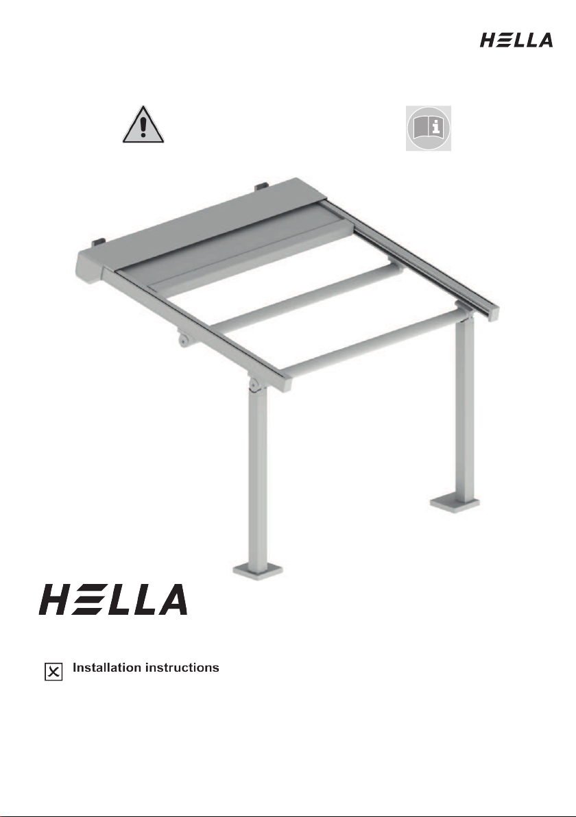
Pergola awning ELEGANZA / ELEGANZA protect

Installation Instructions
Table of Contents
Preliminary remarks HELLA Pergola awning ELEGANZA / ELEGANZA protect..................3
Before installation.................................................................................................................4
Overview: Tools for the installation.......................................................................................5
Overview ELEGANZA ..........................................................................................................6
Column types’ overview........................................................................................................7
Installation box .....................................................................................................................8
Installing the guide rails......................................................................................................13
Installation of the columns..................................................................................................17
Cross brace installation (front)............................................................................................22
Installation pull cords..........................................................................................................26
Installing the lateral end caps.............................................................................................28
Installation of the guiding tubes..........................................................................................29
Installing the anti-lift device ................................................................................................30
Mounting Varioplus roller blind - freely suspended.............................................................32
Mounting Varioplus roller blind - rail-guided .......................................................................33
Installation/wiring LED........................................................................................................38
Malfunctions .......................................................................................................................41
Wiring diagram for motors with ONYX.CONNECTOR........................................................44
Wiring diagram for motors with ONYX.NODE ....................................................................45
Wiring diagram for motors with Somfy io............................................................................46
Wiring diagram for motors with switch operation................................................................47
Wiring diagram for LED lighting ONYX/Somfy io................................................................48
Operating instructions and configuration with ONYX..........................................................49
Instructions for use and configuration with Somfy ..............................................................50
Activation guidelines for electric drives...............................................................................51
Commissioning/functional check ........................................................................................52
Removal .............................................................................................................................53
Installation Instructions
Subject to technical modifications. – Date of Issue
September/2023
3
Preliminary remarks HELLA
Pergola awning ELEGANZA / ELEGANZA protect
With this HELLA product you have opted for a high-quality product with a most up-to-date
technology that can nevertheless be easily installed and operated. In these instructions we
describe the basic installation, commissioning and use.
For authorized specialist staff
For the consumer (user)
The following symbols will assist you with the installation or use and require a safety-
conscious conduct:
Attention!
This symbol indicates instructions that, if disregarded, can put the user in
danger.
Attention!
This symbol indicates instructions that, if disregarded, can potentially result
in damage to the product.
This symbol indicates instructions for use or helpful information.
This symbol requires you to act.
Attention!
This symbol indicates a risk of injury or danger to life due to an electric
shock.
This symbol indicates parts of the product, for which you will find important
information in these installation instructions.
Installation Instructions
4
Subject to technical modifications. – Date of Issue
September/2023
Before installation
Check the product immediately for possible shipping damage and for
compliance with the delivery receipt.
If parts are missing or damaged, please consult your supplier immediately.
Check the mounting base and ensure that the mounting material to be used
complies with the given conditions to guarantee proper installation. In case
of doubt, please seek advice from a specialist enterprise for fixing
techniques.
The packaging cardboard box should not be exposed to humidity. To
protect it from rain during transport, it should be covered by a foil.
Carry larger units by two persons. Transport and store the units carefully to
prevent injury of persons and damage to the product.
Remove the packaging material carefully. When using a knife, be careful
not to damage the packaging content and to avoid cuts!
Dispose of the packaging material via recycling.
Caution!
A wrong installation can endanger the user seriously. Please strictly
observe the installation instructions. Close off the place of installation.
When working at higher heights, there is risk of falling. Suitable ascent
supports, scaffoldings and fall protection devices are to be used. Please
make sure that the ascent supports stand solidly and provide a firm grip.
Installation Instructions
Subject to technical modifications. – Date of Issue
September/2023
5
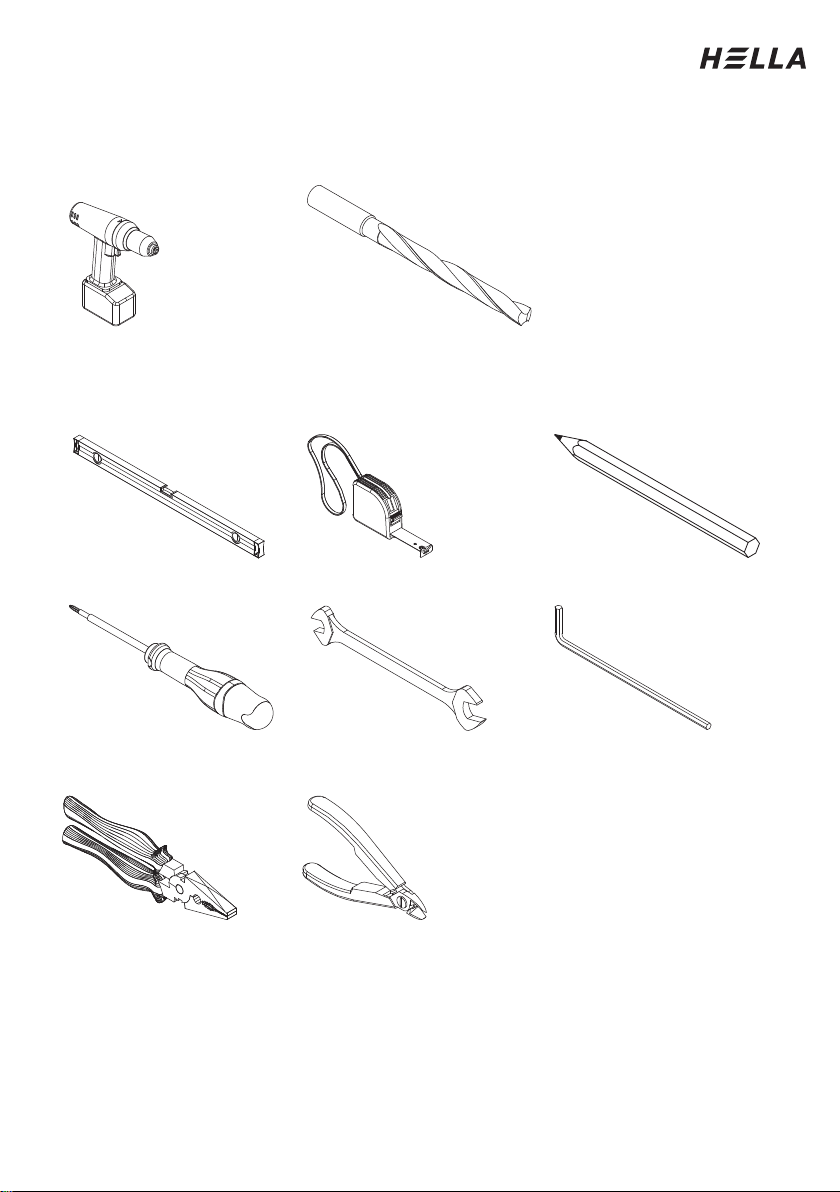
Overview: Tools for the installation
Battery-powered drill
Depending on the mounting
base (Bit AW 10, AW 20)
Bit extension
Drilling bit
Drill set
acc. to Mounting base
Level Measuring tape Pencil
Screwdriver Spanners
or ratchet
Allen key
Combination pliers or
long-nosed pliers
Side cutter
Installation Instructions
6
Subject to technical modifications. – Date of Issue
September/2023
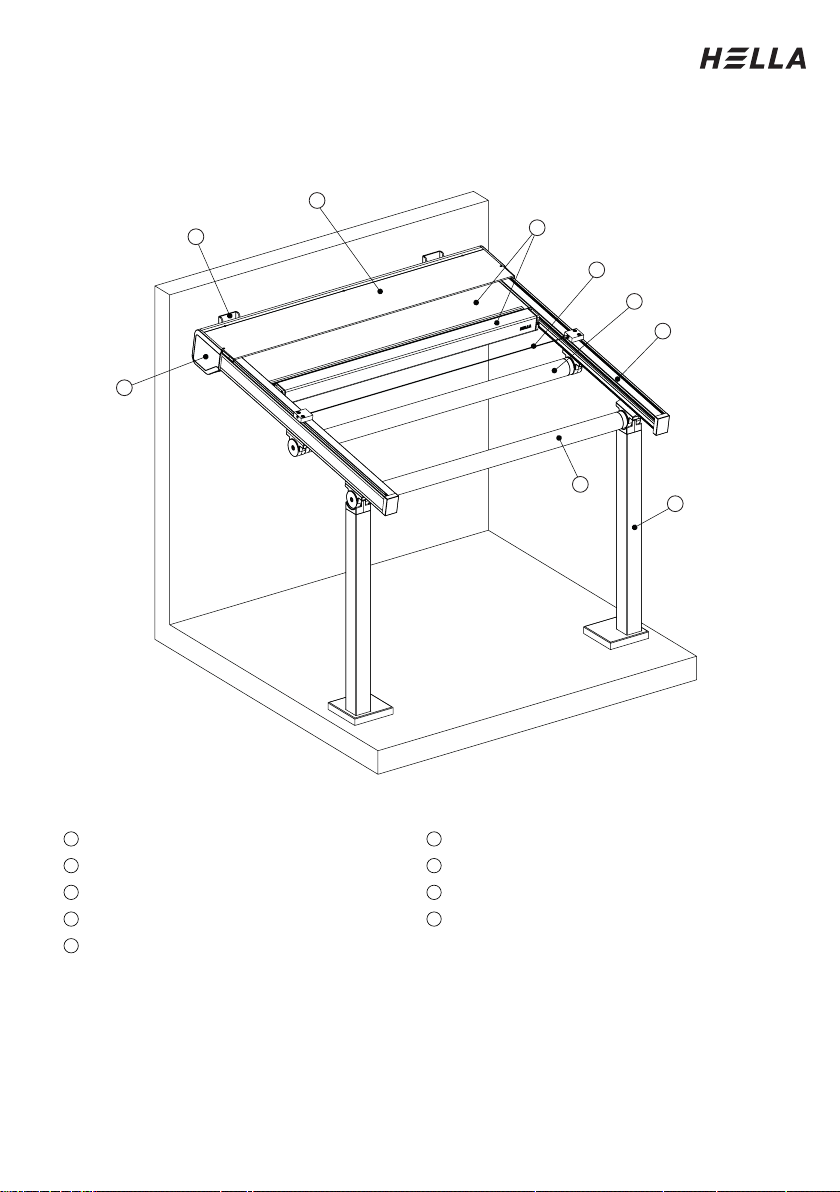
Overview ELEGANZA
Legend
Box (2-part)
With column fixed (standard)
Wall bracket Type A
Conduit
Lateral end cap
Anti-lift device
Guide rail
Curtain and front rail
Cross-beam round
1
6
2
7
3
8
4
9
5
1
2
3
4
5
6
7
8
9
Installation Instructions
Subject to technical modifications. – Date of Issue
September/2023
7
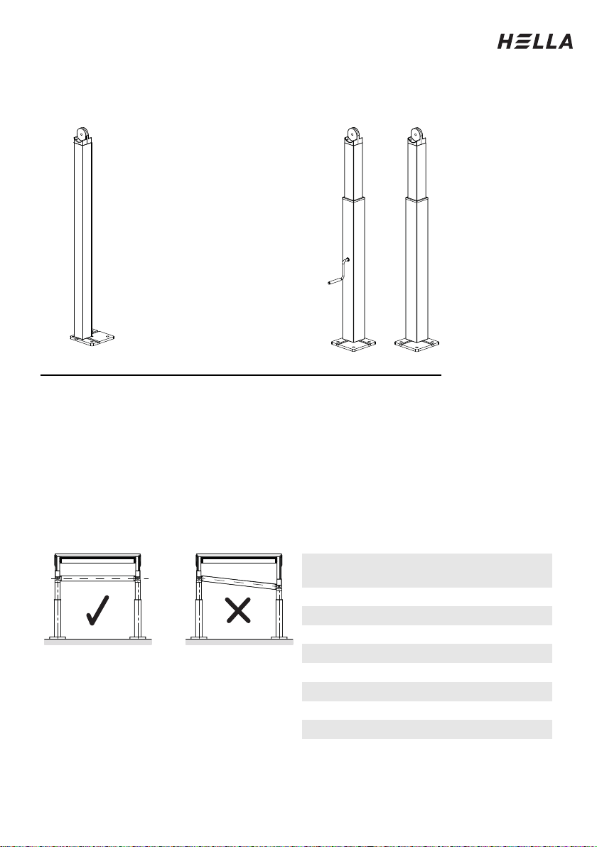
Column types’ overview
fixed column (std) lowerable column (optional)
Important information regarding the usage of a lowerable column:
- Only one column may be lowerable per unit.
- In the case of combined units, centre columns must not be lowerable under any
circumstances, i.e. columns that can be lowered with a hand crank may only be installed
as edge columns.
- The range of lowering depends on the final width of the unit and is already set and
limited ex-works. This adjustment range must not be changed independently under any
circumstances.
- The unit may not be retracted or extended under any circumstances when the column is
lowered. For driving operation, the lowerable column must be cranked up so that the
front cross brace is horizontal.
Disregarding these instructions can cause damage to the units.
Complete width
[mm]
max. lowering
2000
110
2500
130
3000
160
3500
190
4000
210
4500
240
5000
260
5500
290
6000
320
Installation Instructions
8
Subject to technical modifications. – Date of Issue
September/2023
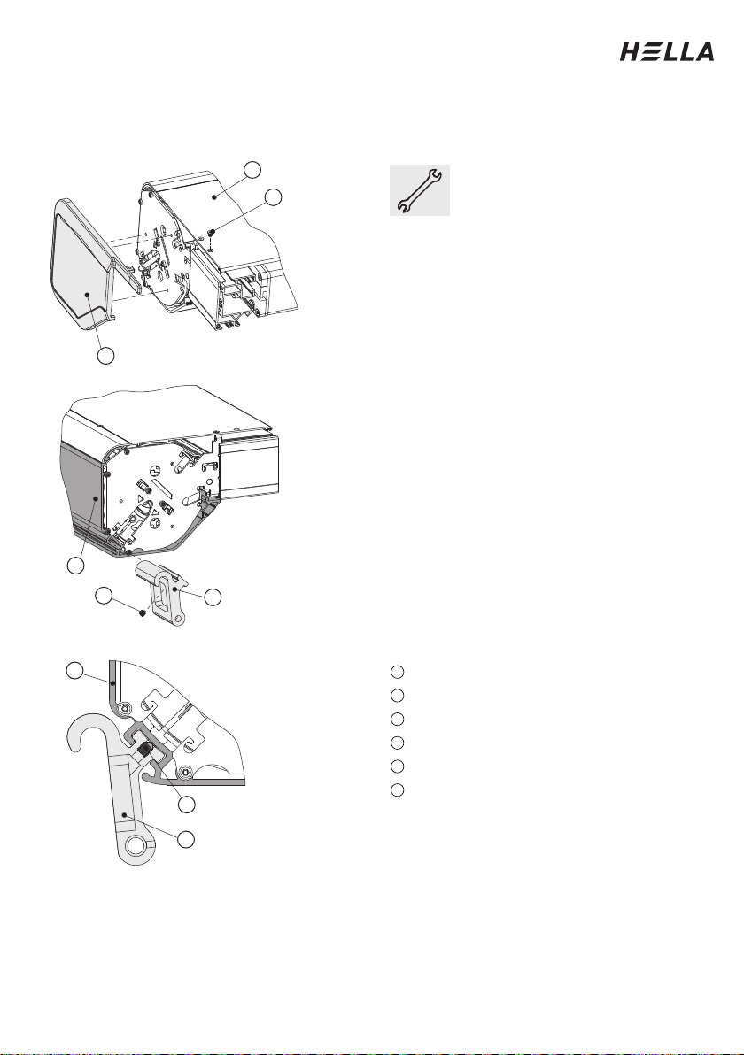
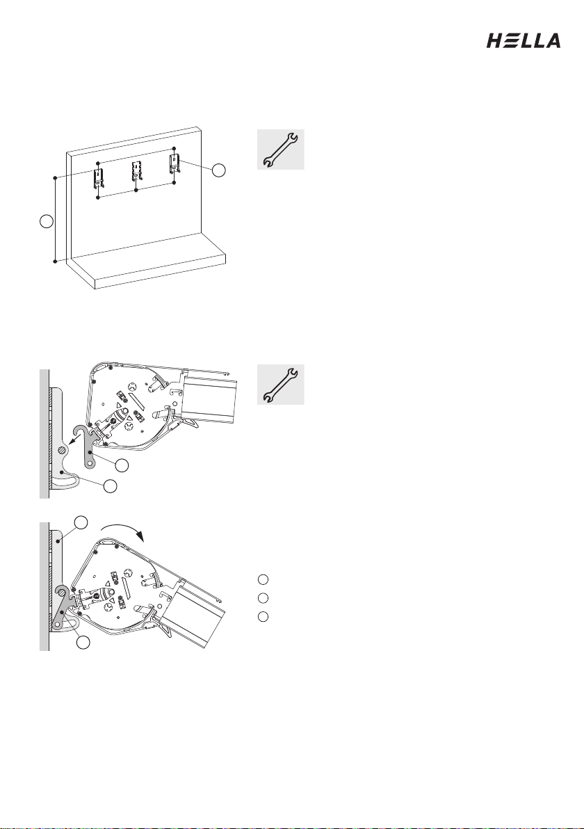
Installation box
Slide in suspension brackets
Take the box out of the
cardboard packaging and
remove the foils. Place the
box on two prepared trestles.
Remove the lateral covering
caps (1). For this, loosen the
countersunk screw (2) in the
upper covering profile (3).
Then pull the covering cap
off to the side.
Slide the hanging consoles
(4) supplied into the groove
of the lower covering profile
(6). Then screw the threaded
pin (5) into the hanging
console.
Three suspension brackets
are supplied from a complete
width of 4000 mm; and only
two up to this complete
width.
Legend
Lateral end cap
Countersunk screw M4x6
Roof profile
Hanging console
Threaded pin M6x8
Lower covering profile
1
2
3
4
5
6
4
5
6
1
2
3
4
5
6
Installation Instructions
Subject to technical modifications. – Date of Issue
September/2023
9
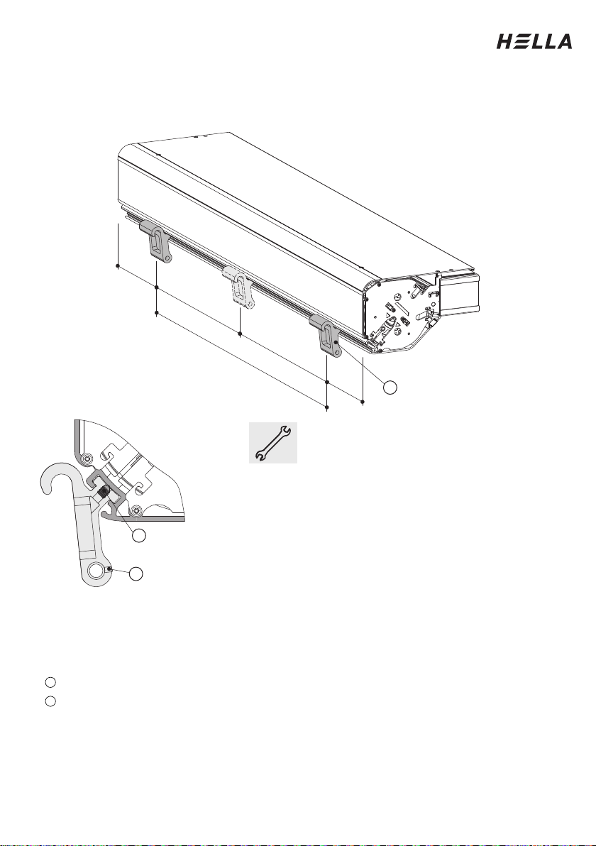
Installation box
Distribute the suspension brackets
Legend
Threaded pin M6x8
Hanging console
Divide the hanging consoles (2) evenly
over the width of the box. Make sure
that the edge distances (<=500 mm) of
the outer brackets are not exceeded.
Clamp the brackets by tightening the
threaded pins (1).
Then measure dimension B (distance
between the outer hanging consoles).
This dimension is needed for marking
the positions of the mounting brackets
on the wall.
The third hanging console (from FB
4000 mm) is always mounted exactly in
the middle between the two outer
hanging consoles.
1
2
500
≤
500
≤
==
B
2
2
1
Installation Instructions
10
Subject to technical modifications. – Date of Issue
September/2023
Installation box
Mounting the mounting brackets on the wall
Draw the mounting positions of the
wall brackets (2) on the wall. The
distance between the two outer
wall brackets corresponds to the
previously measured dimension B.
Please refer to the order papers for
the mounting height (1).
Attach the wall brackets (2) to the
wall using the appropriate
mounting material.
Position two ladders of the same
height below the mounting
brackets.
Hanging the box in the wall bracket
Place the box on the top of the
ladders. Please make sure that the
box is placed safely and that it
cannot fall down.
Lift the box evenly in pairs and
hang the box with the hanging
consoles (3) in the bolts of the wall
brackets (2).
When you have hinged in the box
and released it, it lowers down until
the hanging console is in contact
with the wall bracket.
Legend
Mounting/complete height
Wall bracket
Hanging console
1
2
3
=
=
B
1
2
2
2
3
3
Installation Instructions
Subject to technical modifications. – Date of Issue
September/2023
11
Installation box
Screwing in the threaded pins and securing them
Put the threaded bolt (1) from the mounting material into the passage in the
hanging console (2) and then turn it through the thread on the other side of
the hanging console. Turn the threaded bolt through the entire thread in the
hanging console.
Then turn the hexagon screw (3) into both sides of the threaded bolt (1), in
order to secure the bolt. First push the washer (4) over the hexagon screw.
Legend
Threaded bolt (on the face side with inner thread)
Hanging console
Hexagon screw M6x20
Washer M6
1
2
3
4
1
21
21
3
4
Installation Instructions
12
Subject to technical modifications. – Date of Issue
September/2023
Installation box
Screwing in the threaded pins and securing them
Secure the threaded bolt
additionally by screwing the
threaded pin (1) into the
threaded hole in the hanging
console (2).
Legend
Threaded pin M4x4
Hanging console
Removing the transportation lock
Loosen the threaded pin (2).
Which is screwed into the
lug of the side part (3).
However, do not unscrew
the threaded pin completely.
Then push the transport
safety device (1) to the front.
Legend
Transport safety device
Threaded pin M8x8
Side part
1
2
1
2
3
2
1
1
2
3
3
1
Installation Instructions
Subject to technical modifications. – Date of Issue
September/2023
13
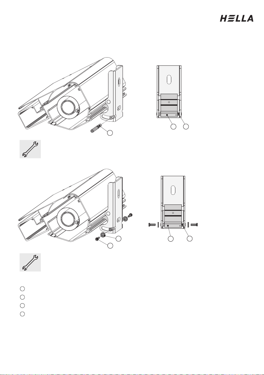
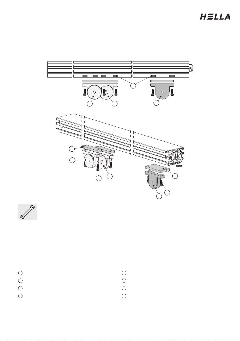
Installing the guide rails
Preparations single guide rail before mounting
Mounting the guiding tube holder and the holder for the cross brace on the guide
rail
Place the guide rails (1) on two prepared trestles. Push the sliding blocks
(6) - 2 per bracket - into the groove of the guide rail. Screw the conduit
bracket (2) with the sliding blocks (6). Only slightly fasten the screws on the
bracket for the cross-beam (3), so that the bracket is still moveable.
The position of bracket (2) and (3) should be identical on the left and right
guide rail.
The spacer plate (5) must always be aligned in a way that the slanted side
of the plate faces the slanted part of the guide rail.
Legend
Guide rail
Spacer plate for bracket of cross profile
Conduit bracket
Sliding block
Bracket for cross-beam
Cylinder-head screw M8x22
(for conduit bracket)
Spacer plate for conduit bracket Cylinder-head screw M8x25
(for bracket cross-beam)
1
5
2
6
3
7
4
8
23
1
6
5
3
2
4
6
78
Installation Instructions
14
Subject to technical modifications. – Date of Issue
September/2023
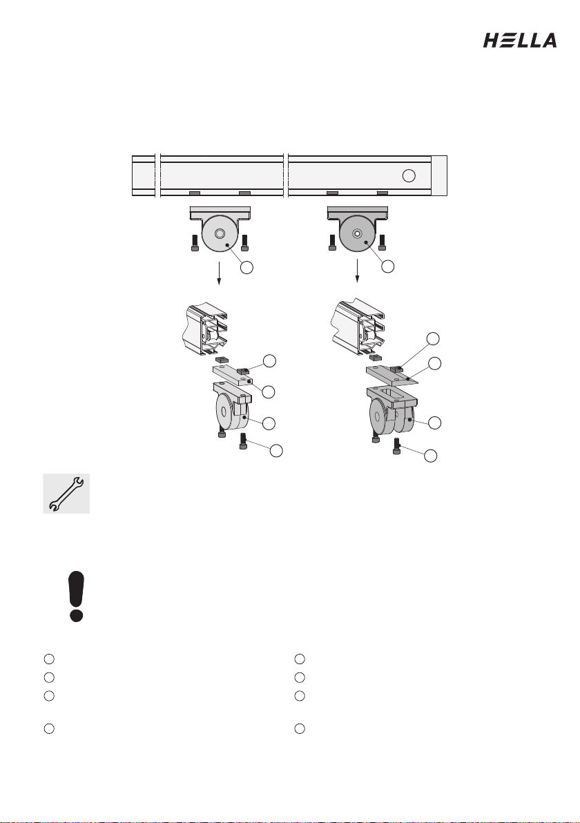
Installing the guide rails
Preparations double guide rail before mounting
Mounting the guiding tube holder and the centre joint on the guide rail
Place the double guide rail on two prepared trestles. Push the sliding blocks
(4) - 2 per bracket - into the groove of the guide rail. Screw the conduit
bracket (1) and the conduit bracket (2) with the sliding blocks (4). Do not
forget the spacer plate (5). Please make sure that the conduit brackets (1
and 2) are slightly displaced, so that the conduit brackets can be screwed
afterwards.
Screw the middle hinge (3) with the sliding blocks. Do not forget the spacer
plate (6). Only slightly fasten the screws of the middle hinge (3), so that it
can still be moved.
Legend
Conduit bracket for installation 1
Spacer plate for conduit bracket
Conduit bracket for installation 2
Spacer plate for middle hinge
Middle hinge
Fillister head screw M8x22
Sliding block
Fillister head screw M8x25
1
5
2
6
3
7
4
8
4
3
2
1
1
5
72
3
6
8
Installation Instructions
Subject to technical modifications. – Date of Issue
September/2023
15
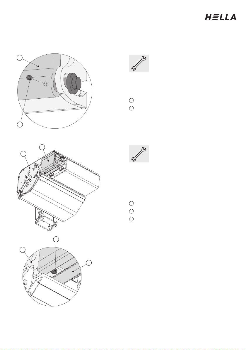
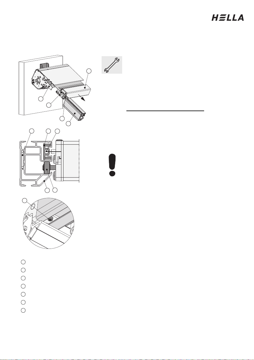
Installing the guide rails
Place the guide rails onto the box.
First extend the front rail by approx. 15 cm.
To do this, connect the unit to a test cable
and operate the unit.
Insert the runners (6) of the front rail (1) into
the channel provided in the guide rail.
Only with ELEGANZA protect:
With ELEGANZA protect systems, the zip
fastener (5) of the cover must be threaded
into the inner guide strips (4) beforehand.
Push the guide rail (2) over the strut (3) of
the side part further until it stops.
Caution with systems with LED or Varioplus:
Follow the instructions on the next page.
Tighten the threaded pin (7) in the lug of the
side part. This clamps the guide rail to the
side part. When sliding the guide rails on,
place cardboard or such under the end of
the guide rail to prevent scratching.
Legend
Front rail
Guide rail
Strut of the side part
Inner guide strip (with ELEGANZA protect)
Zip fastener (with ELEGANZA protect)
Guide rollers
Threaded pin (in the lug of the side part)
1
2
3
4
5
6
7
7
26
5
4
3
2
4
1
5
3
Installation Instructions
16
Subject to technical modifications. – Date of Issue
September/2023
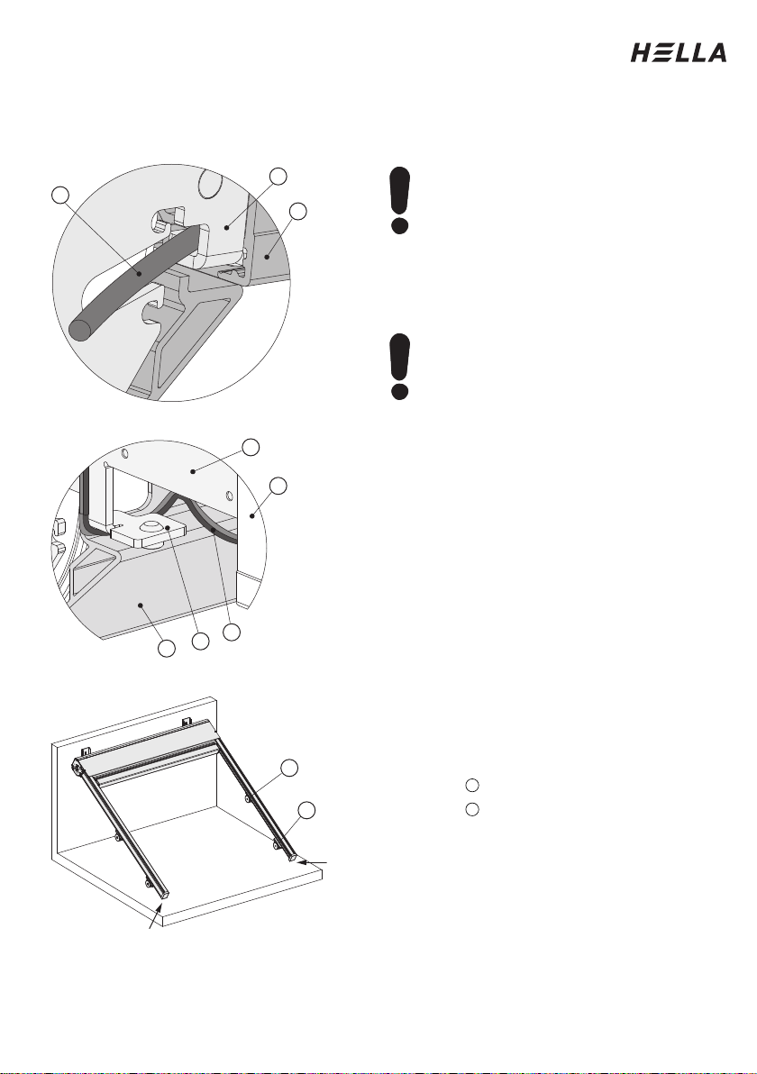
Installing the guide rails
Place the guide rails onto the box.
Attention for systems with
Varioplus:
For systems with Varioplus roller
blind, make sure that the
protruding retraction aid (4) on
the drive side guide rail (5) is
guided out at the corresponding
point in the side part (3).
Attention for guide rails with
LED:
When sliding on, it must be
ensured that the cable (7) of the
LED strips is not damaged. The
cable (7) must be threaded
through under the lug (8) and
then it runs outwards between
the lug (8) and the lower covering
profile (6).
When the guide rails are
mounted, the box, together with
guide rails, hang on the wall. For
units with small sloping
projection, it is advisable to
underlay the ends of the guide
rails (e.g. with trestles) - as a
relief. Units with larger sloping
projection support themselves via
the guide rails on the floor.
Legenda
Conduit bracket
Bracket for cross-beam
1
2
5
3
4
687
5
3
1
2
Installation Instructions
Subject to technical modifications. – Date of Issue
September/2023
17
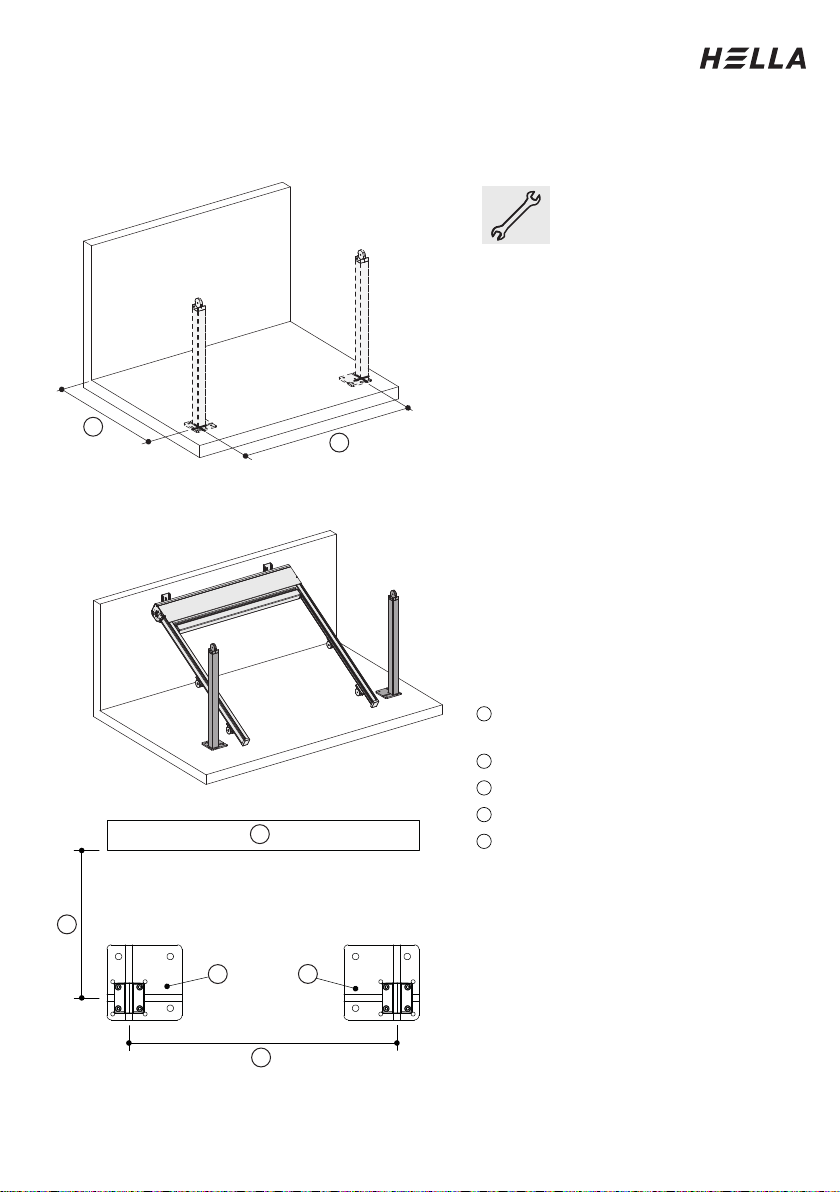
Installation of the columns
Marking the column position
Preparing the columns
Mark the mounting
positions of the columns
on the floor. Please take
the column distance (1)
from the order and
measure it from the wall
(fixing level) to the middle
of the column.
Also take the complete
width (2) from the order.
Complete width is the
distance between the
axes of the columns.
Place the columns within
easy reach at the front
end of the guide rails.
In this process, pay
attention to the alignment
of the columns (see
bottom picture).
Legend
Column distance (according to
order)
Complete width (as per order)
Wall
Column on the left side
Column on the right side
1
2
3
4
5
2
1
3
45
1
2
Installation Instructions
18
Subject to technical modifications. – Date of Issue
September/2023
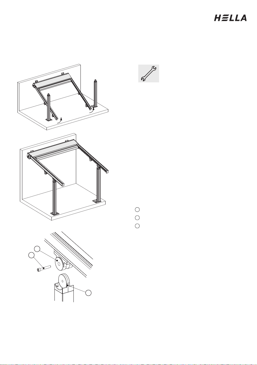
Installation of the columns
Swivelling the unit open
Swivel the unit up evenly on
both sides.
Hold the unit in position.
Take the column and place it
under the guide rail.
To do this, slide the bracket
for the cross-beam (1) over
the attachment (2), which is
mounted on top of the
column.
Insert the screw (3) from the
outside inwards through the
boreholes, to connect the
column with the guide rail.
Two persons are required for
this entire step.
Legend
Bracket for cross-beam
Attachment (mounted on the column)
Fillister head screw M10x70
1
2
3
2
3
1
Installation Instructions
Subject to technical modifications. – Date of Issue
September/2023
19
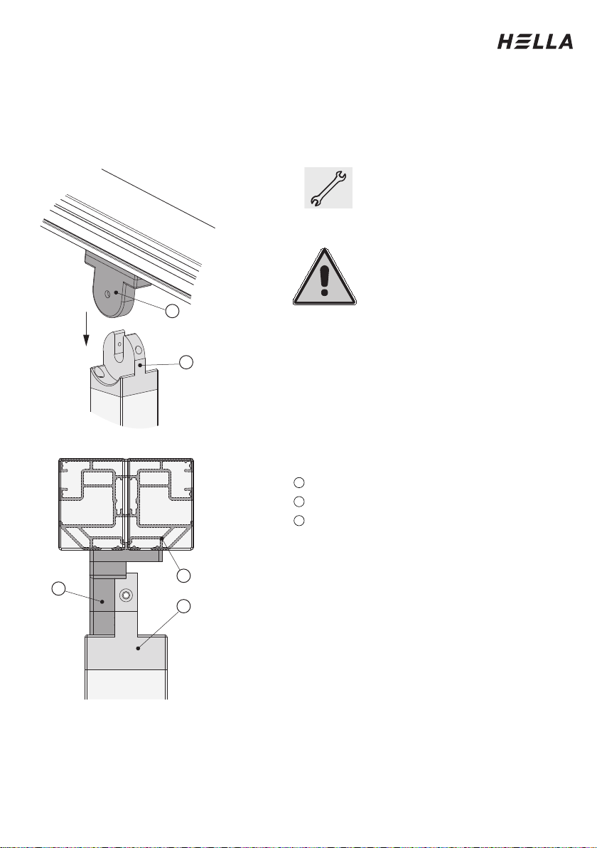
Installation of the columns
Swivelling the unit open
To be noted at the
middle situation!
When you have swivelled the
unit upwards, hold it in position.
Then place the double guide
rail (3) on the centre column.
Make absolutely sure that the
middle hinge (1), which is
mounted on the guide rail,
rests on the attachment (2) of
the centre column. The double
guide rail is only connected
with the column by installing
the front cross-beam.
After aligning the system, be
sure to tighten the screws,
which secure the middle hinge
(1) to the guide rail.
Legend
Middle hinge
Attachment (on the centre column)
Double guide rail
1
2
3
2
3
1
2
1
Installation Instructions
20
Subject to technical modifications. – Date of Issue
September/2023
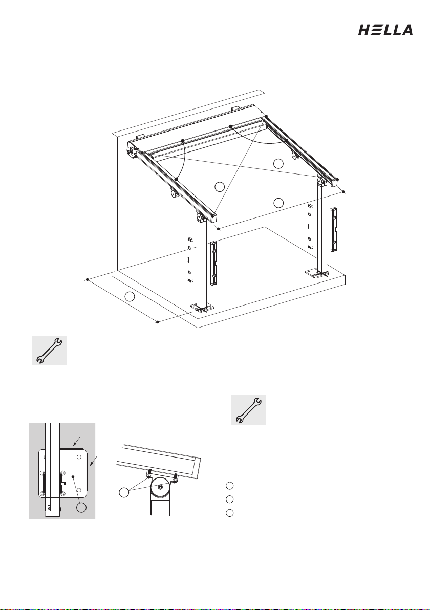
Installation of the columns
Aligning the unit
Place the columns in the previously marked positions. Remeasure the
diagonals (1) and the widths (2, 3). The diagonal dimension as well as the
width dimensions must be equal. Verify that the guide rails are
perpendicular to the box. If necessary, the columns must be moved slightly.
Align the columns on all sides using a spirit level.
Please mark the final
position of the column base
(4) on the floor after
alignment. Tighten the
screws (5) in the bracket for
the cross-beam.
Legend
Column distance (according to order)
Column base
Screws in bracket cross-beam
(M8*25)
3
4
5
90°
90°
3
1
2
1
4
5
Other manuals for ELEGANZA
1
This manual suits for next models
1
Table of contents
Other Hella Lawn And Garden Equipment manuals


