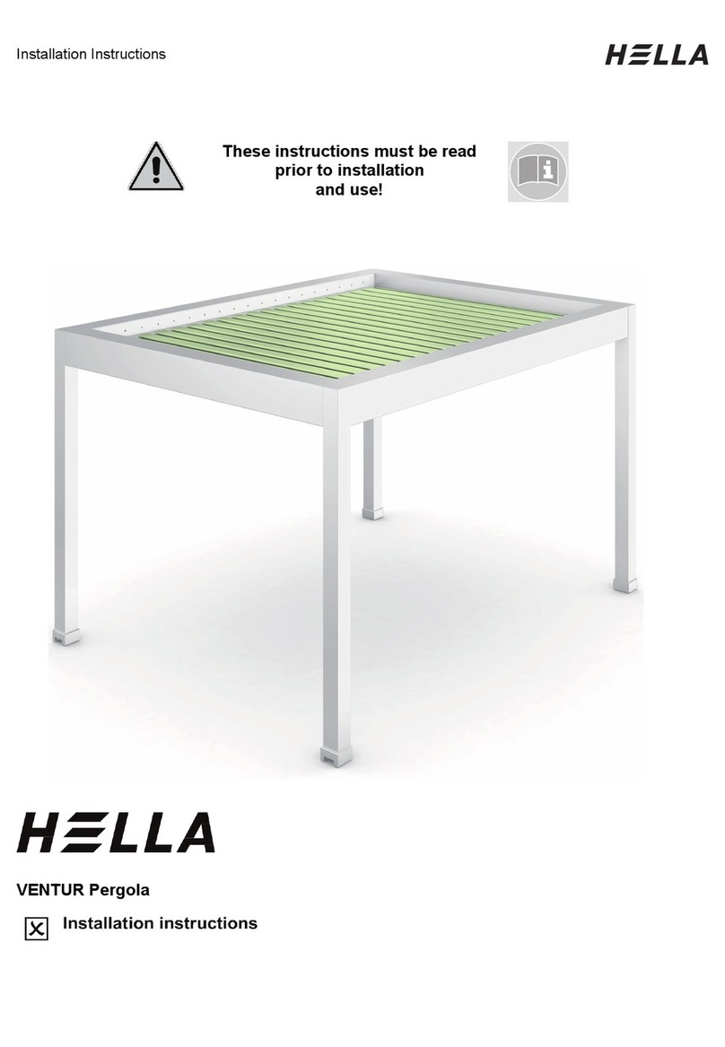
Hella SOLEYA User manual

Installation Instructions
These instructions must be read
prior to installation
and use!
Over-glass and under-glass awning SOLEYA/SOLEYA protect

Installation Instructions
Table of Contents
Preliminary remarks HELLA Over-glass and under-glass awning SOLEYA/SOLEYA protect
.............................................................................................................................................3
Before installation.................................................................................................................4
Overview: Tools for the installation.......................................................................................5
Overview SOLEYA/SOLEYA protect - under-glass ..............................................................6
Under-glass mounting brackets overview.............................................................................7
Mounting SOLEYA/SOLEYA protect - under-glass ............................................................11
Adjusting the Underglass Awning.......................................................................................35
Overview SOLEYA/SOLEYA protect - over-glass ..............................................................37
Over-glass mounting brackets overview.............................................................................38
Mounting SOLEYA/SOLEYA protect - over-glass ..............................................................40
Aligning the over-glass awning...........................................................................................63
Installation/wiring LED........................................................................................................65
Malfunctions .......................................................................................................................68
Wiring diagram for motors with ONYX.CONNECTOR........................................................71
Wiring diagram for motors with ONYX.NODE ....................................................................72
Wiring diagram for motors with Somfy io............................................................................73
Wiring diagram for motors with switch operation................................................................74
Wiring diagram for LED lighting ONYX/Somfy io................................................................75
Operating instructions and configuration with ONYX..........................................................76
Activation guidelines for electric drives...............................................................................78
Commissioning/functional check ........................................................................................79
Removal .............................................................................................................................80

Installation Instructions
Subject to technical modifications. – Date of Issue
September/2023
3
Preliminary remarks HELLA
Over-glass and under-glass awning
SOLEYA/SOLEYA protect
With this HELLA product you have opted for a high-quality product with a most up-to-date
technology that can nevertheless be easily installed and operated. In these instructions we
describe the basic installation, commissioning and use.
For authorized specialist staff
For the consumer (user)
The following symbols will assist you with the installation or use and require a safety-
conscious conduct:
Attention!
This symbol indicates instructions that, if disregarded, can put the user in
danger.
Attention!
This symbol indicates instructions that, if disregarded, can potentially result
in damage to the product.
This symbol indicates instructions for use or helpful information.
This symbol requires you to act.
Attention!
This symbol indicates a risk of injury or danger to life due to an electric
shock.
This symbol indicates parts of the product, for which you will find important
information in these installation instructions.

Installation Instructions
4
Subject to technical modifications. – Date of Issue
September/2023
Before installation
Check the product immediately for possible shipping damage and for
compliance with the delivery receipt.
If parts are missing or damaged, please consult your supplier immediately.
Check the mounting base and ensure that the mounting material to be used
complies with the given conditions to guarantee proper installation. In case
of doubt, please seek advice from a specialist enterprise for fixing
techniques.
The packaging cardboard box should not be exposed to humidity. To
protect it from rain during transport, it should be covered by a foil.
Carry larger units by two persons. Transport and store the units carefully to
prevent injury of persons and damage to the product.
Remove the packaging material carefully. When using a knife, be careful
not to damage the packaging content and to avoid cuts!
Dispose of the packaging material via recycling.
Caution!
A wrong installation can endanger the user seriously. Please strictly
observe the installation instructions. Close off the place of installation.
When working at higher heights, there is risk of falling. Suitable ascent
supports, scaffoldings and fall protection devices are to be used. Please
make sure that the ascent supports stand solidly and provide a firm grip.

Installation Instructions
Subject to technical modifications. – Date of Issue
September/2023
5
Overview: Tools for the installation
Battery-powered drill
Depending on the mounting
base (Bit AW 10, AW 20)
Bit extension
Drilling bit
Drill set
acc. to Mounting base
Level Measuring tape Pencil
Screwdriver Spanners
or ratchet
Allen key
Combination pliers or
long-nosed pliers
Side cutter

Installation Instructions
6
Subject to technical modifications. – Date of Issue
September/2023
Overview SOLEYA/SOLEYA protect - under-glass
Legend
Covering cap
Mounting bracket for wall/ceiling installation
Box (3-part)
Guide rail
Tensioner for the cover supporting wire
Mounting bracket for guide rail
Front rail
1
2
3
4
5
6
7
1
23
4
5
6
7

Installation Instructions
Subject to technical modifications. – Date of Issue
September/2023
7
Under-glass mounting brackets overview
Standard brackets
Mounting bracket guide
rail
Mounting angle ceiling
installation
Mounting bracket wall
installation
U1-F30
Type
Bracket height
U1-F30
30 mm
DU-157
Type
Bracket height
DU-157
157 mm
WU-120
Type
Bracket height
WU-120
120 mm
Mounting bracket guide
rail, linkage
Mounting bracket guide
rail, line
U2-F30
Type
Bracket height
U2-F30
30 mm
U4-F30
Type
Bracket height
U4-F30
30 mm

Installation Instructions
8
Subject to technical modifications. – Date of Issue
September/2023
Under-glass mounting brackets overview
Standard brackets
Tensioner for the cover supporting wire Angle bracket for support
wires for the cover,
linkage
TU-135
Type
Bracket height
TU-135
135 mm
04170514
Bracket height
110 mm

Installation Instructions
Subject to technical modifications. – Date of Issue
September/2023
9
Under-glass mounting brackets overview
Special brackets
Mounting bracket guide
rail
Mounting bracket guide
rail, linkage
Mounting bracket guide
rail, line
U1-F
Type
Bracket height
U1-F80
80 mm
U1-F130
130 mm
U2-F
Type
Bracket height
U2-F80
80 mm
U2-F130
130 mm
U4-F
Type
Bracket height
U4-F80
80 mm
U4-F130
130 mm
Mounting angle ceiling
installation
Tensioner for the cover supporting wire
DU-200
Type
Bracket height
DU-200
200 mm
Type
Bracket height
TU-185
185 mm
TU-235
235 mm

Installation Instructions
10
Subject to technical modifications. – Date of Issue
September/2023
Under-glass mounting brackets overview
Special brackets
04210512
04210524
04210525
Mounting bracket for guide
rail
30x40 mm
Mounting bracket for guide
rail
50x50 mm
Mounting bracket for guide
rail
80x60 mm
04210526
Mounting bracket for
distance, motor/bearing side

Installation Instructions
Subject to technical modifications. – Date of Issue
September/2023
11
Mounting SOLEYA/SOLEYA protect - under-glass
Fastening mounting brackets
Please check, if the mounting
brackets supplied comply with
your order.
The mounting angles are
installed staggered to the
second rafter opposite of the
mounting brackets
respectively.
Adjust the mounting angles in
height and depth by using a
chalk line.
Mark the boreholes on the
rafter.
Bore the holes at the specified
positions, and fix the mounting
brackets.
Legend
Mounting angle for ceiling installation
Mounting angle for wall installation
Mounting bracket for guide rail 30 mm
1
2
3
12
157
1
2
3

Installation Instructions
12
Subject to technical modifications. – Date of Issue
September/2023
Mounting SOLEYA/SOLEYA protect - under-glass
Fastening mounting brackets
Linked units
Adjust the mounting angles in
height and depth by using a
chalk line.
Legend
Mounting angle for ceiling installation
Mounting bracket for wall installation
Chalk line
1
2
3
1
3
2
3

Installation Instructions
Subject to technical modifications. – Date of Issue
September/2023
13
Mounting SOLEYA/SOLEYA protect - under-glass
Fastening mounting brackets
Please check if the mounting
brackets supplied for the guide
rails comply with your order.
Loosen the clamping pin by
means of an Allen key (4 mm).
Mark the mounting brackets on
the rafters. Bore the holes at
the specified positions, and fix
the mounting brackets.
Please ensure that the
mounting brackets are in
alignment. If necessary, shift
them laterally.
Legend
Mounting bracket for guide rails 30 mm,
standard design
Mounting bracket for guide rails, linkage
1
2
1
2

Installation Instructions
14
Subject to technical modifications. – Date of Issue
September/2023
Mounting SOLEYA/SOLEYA protect - under-glass
Fastening mounting brackets
Installation angle bracket for support wires for the cover
Legend
Mounting angle for ceiling
installation
Mounting bracket for guide rail,
under-glass
Angle bracket for support wires for
the cover
If the width or projection of the
awning field exceeds 4000
mm, the cover may
increasingly sag. By using an
additional cover supporting
wire, it is possible to avoid this
effect.
As shown above, fix the angle
brackets (3) to the outermost
rafter, in the middle of the
sloping projection of the
awning.
The fixing dimension middle of
the hole of the mounting
brackets (2) is also the fixing
dimension middle of the hole
of the angle brackets (3).
1
2
3
350 ≤ 2000 80-300
1
23
2
3

Installation Instructions
Subject to technical modifications. – Date of Issue
September/2023
15
Mounting SOLEYA/SOLEYA protect - under-glass
Fastening mounting brackets
Linked units
Legend
Dimension between axes = ordering dimension (1st unit)
Dimension between axes = ordering dimension (2nd unit)
Mounting angle for ceiling installation
1
2
3
12
3

Installation Instructions
16
Subject to technical modifications. – Date of Issue
September/2023
Mounting SOLEYA/SOLEYA protect - under-glass
Fastening mounting brackets
Installation in the soffit
Legend
Ordering dimension axis of the guide
rail
Angular bracket for installation in the
soffit, offset 30 mm (60 mm)
Mounting bracket for guide rail,
under-glass
Guide rail
The angular brackets for the
installation in the soffit are
loosely enclosed in the
delivery.
Hold the angular bracket for
the installation in the soffit to
the wall and mark the
boreholes for the fixing.
Provide suitable boreholes for
the fixing.
Fix the angular bracket to the
mounting base by using the
appropriate mounting material,
and adjust it.
Fasten the mounting brackets
to the angular brackets.
Please ensure that the
mounting brackets are in
alignment. If necessary, shift
them laterally.
Please observe the offset
between the axis of the guide
rail and the outer edge of the
angle of 30 mm or 60 mm.
1
2
3
4
30 (60)
1
2
3
4

Installation Instructions
Subject to technical modifications. – Date of Issue
September/2023
17
Mounting SOLEYA/SOLEYA protect - under-glass
Installation awning box
Single and linked units
Place the awning on two
prepared trestles.
Unpack the awning (carton,
film).
Remove the lateral covering
caps (4). To do this, loosen the
screw connection with the
lower covering profile (1) and
pull the cover cap off to the
side.
Now remove the lower
covering profile (1) by
loosening the screw
connection and unhooking the
lower covering profile from the
supporting yoke (3). Then lay
the lower covering profile
aside.
Linked units
Remove the clamping pins (2)
from the linkage and pull the
linkage apart.
Legend
Lower covering profile
Clamping pins
Supporting yoke
Lateral end cap
1
2
3
4
4
1
3
2
2
2

Installation Instructions
18
Subject to technical modifications. – Date of Issue
September/2023
Mounting SOLEYA/SOLEYA protect - under-glass
Installation awning box
Single and linked units
Position two ladders of the
same height below the
mounting brackets.
Place the awning box on the
top of the ladders. Please
make sure that the awning box
is placed safely and that it
cannot fall down.
Do never work in larger
heights, especially on
balconies, without suitable
fall protection devices!
Lift the awning box evenly with
two persons. Hinge the awning
box completely horizontally
into the mounting brackets (1).
Legend
Mounting bracket
Awning box (box profile)
Transport safety device
1
2
3
3
1
2

Installation Instructions
Subject to technical modifications. – Date of Issue
September/2023
19
Mounting SOLEYA/SOLEYA protect - under-glass
Installation awning box
Single and linked units
Legend
Mounting bracket
Awning box (box profile)
Transport safety device
Front rail
Carefully allow the front rail
(4) to move out of the
transport lock (3). To do
this, connect the motor(s)
to a test cable and operate
the awning.
Remove the small
countersunk screws from
the projecting parts of the
cheeks.
Remove the transport lock
(3).
Linked units
Position the ladders below
the mounting brackets of
the next awning.
Also hinge the awning box
carefully into the mounting
brackets, extend the front
rail and unscrew the
countersunk screws.
Remove the transport lock
(3).
1
2
3
4
2
3
3
4
1

Installation Instructions
20
Subject to technical modifications. – Date of Issue
September/2023
Mounting SOLEYA/SOLEYA protect - under-glass
Installation awning box
Linking the units
Put the outer (1) and the
inner part (2) of the linkage
into the linkage opening of
the right and the left
awning (only with two
awnings with one motor).
Make sure that the slits (3)
of the linkage parts engage
in the inner bolt of the
spring mechanics (4) (only
with two awnings with one
motor).
Legend
outer part of the linkage
inner part of the linkage
Slit of the linkage part
inner bolt of the spring mechanics
1
2
3
4
1
2
3
4
3
4
Other manuals for SOLEYA
2
This manual suits for next models
1
Table of contents
Other Hella Lawn And Garden Equipment manuals
Popular Lawn And Garden Equipment manuals by other brands
Sunjoy
Sunjoy L-PG096PAL Assembly instructions
Agrimate
Agrimate AM-MPT-1100-9D/6D-CHAMPION NEW user manual

Exmark
Exmark Ultravac Bagger 126-8680 Setup instructions
OPCOM
OPCOM OFG008G Quick manual guide
Husqvarna
Husqvarna ARBR5120v1 instruction manual
Pond Logic
Pond Logic PondShelter 160350 Assembly instructions
