Helm HELMPAK User manual

HelmPak Press Control
1
Users Guide
Helm Instrument Co. • 361 West Dussel Drive • Maumee, Ohio USA • 419-893-4356
HELMPAK™
Press Control

HelmPak Press Control
2
Users Guide

HelmPak Press Control
3
Users Guide
SECTION 1:
INTRODUCTION........................................................................................................................................... 4
THE HELM-PAK SYSTEM............................................................................................................................. 4
WARNINGS.................................................................................................................................................... 5
SECTION 2:
WHAT IS CLUTCH / BRAKE SOFTWARE?.................................................................................................. 6
POSITION MONITORING............................................................................................................................. 6
PROGRAMMABLE LIMIT SWITCH AND DIE MONITORING BASICS...................................................... 6
SECTION 3:
BASIC OPERATION .................................................................................................................................... 12
MODE OF OPERATION ............................................................................................................................ 13
SHUT DOWN SYSTEM................................................................................................................................ 13
SECTION 4:
SCREEN NAVIGATION............................................................................................................................... 14
LOGIN.......................................................................................................................................................... 15
COUNTERS.................................................................................................................................................. 15
MOTOR CONTROL ..................................................................................................................................... 16
TONNAGE MAIN......................................................................................................................................... 17
TONNAGE ALARMS.................................................................................................................................... 18
SECTION 5:
SYSTEM SETUP ......................................................................................................................................... 19
TONNAGE CALIBRATION ......................................................................................................................... 20
SHUTHEIGHT SETUP ............................................................................................................................... 21
MOTOR SETUP .......................................................................................................................................... 22
ROBOT SETUP ........................................................................................................................................... 23
SECTION 6:
RECIPE SETUP AND DOWNLOAD .......................................................................................................... 24
ACTIVE JOB SETUP .................................................................................................................................. 29
APPENDIX A:
ALARM EXPLANATIONS ........................................................................................................................... 34
LIMITED WARRANTY ........................................................................................................... 43

HelmPak Press Control
4
Users Guide

HelmPak Press Control
5
Users Guide
SECTION 1:
INTRODUCTION
You have just purchased the most advanced press control system available. HELM
INSTRUMENT COMPANY, INC. manufactures a complete line of press control solutions
for use on metal stamping, forging, compaction and assembly presses.
At HELM, quality is inherent not only in the design of our products but in the attitudes of
our employees as well. We’re working together to give you the best. After all, that’s what
our business is all about - providing innovative instrumentation to help make your
manufacturing processes more productive and your operations more efficient.
THE HELM-PAK SYSTEM
Helm-Pak consists of an operator interface type enclosure containing the, run buttons,
press control processors, magnetics and Human Machine Interface (HMI). These
components are laid out for the maximum operator efficiency.
The control enclosure(s) contain Allen-Bradley SLC PLC’s, operating pushbuttons,
selector switches and the operator Interface.
The dual rack configurations provide the redundant control of the clutch and brake
system. Both controllers monitor all clutch/brake I/O and exchange information about
machine status. They are linked by hardwired I/O so if one controller detects a condition
different from that detected by the other, the control logic is designed to declare a fault
and turn off all outputs to press valves. The other controller is designed to follow suit.
Compliance:
The package uses two redundant processors with application software for self testing and
verification to meet the safety requirements of ANSI B11.1, OSHA 1910.217 and
CAN/CSA Z142-M90 press safety regulations for mechanical stamping presses.

HelmPak Press Control
6
Users Guide
REPLACING MODULES
Do not remove modules under power.
The module location in a specific rack is critical to proper operation of the Helm-Pak press control. If a
module is replaced, ensure that the proper module is inserted into the proper slot in the rack. If it is not
the ladder programming will not recognize the module and the Helm-Pak control will become unstable
and unsafe to operate.
TURNING SYSTEM ON
SAFETY FIRST Check all light curtains, barriers, safety shields and
personnel safety devices to ensure that they are present and functioning
properly. If they are not, do not proceed with starting the press. Authorized
personnel should make any repairs that are required before starting the press.
Alwa
y
s wear e
y
e and ear
p
rotection when o
p
eratin
g
a stam
p
in
g
p
ress.

HelmPak Press Control
7
Users Guide
SECTION 2:
CLUTCH / BRAKE SOFTWARE
The HelmPak Clutch/Brake Control System is a bundle of hardware, software, and
engineering documents designed to control the clutch and/or brake mechanism on a
mechanical stamping press that has a part-revolution friction clutch and/or brake. This
system uses two processors for clutch/brake control.
The clutch/brake control system is designed to signal brake wear by monitoring the brake
monitor cam (BCAM). Should it see the BCAM closed after a normal cycle stop has been
initiated and before the press comes to a top stop, it is designed to protect against press
restart. System
I/O modules in both Clutch/Brake chassis are identical for clutch/brake control. If the
processor in one chassis detects a condition different from that detected by the other, its
control logic is designed to declare a fault and turn off all outputs to press valves. The
other processor is designed to follow suit. Dual processors control outputs to
clutch/brake valve. Chapter 1
Clutch/Brake Modes:
The operator can select the mode of control system operation with the selector switch
located on a control panel.
Mode Operation
Inch Jog the press through successive parts of the cycle by pressing and
releasing the pair of INCH buttons. If INCH buttons are held, the press
will stop at the top of its stroke, if inch stop on top is enabled in the setup
menu.
Single-stroke Run the press through one complete cycle by holding both RUN buttons
until completion of the down stroke.
Continuous Run the press in a single on demand manner until stopped by a stop-on-
top command or until a fault is detected. The method to start the press is
a factory configured option where operator presses the CONTINUOUS
SETUP button and press both RUN buttons in all active stations within
five seconds.
POSITION MONITORING
•The Helm-Pak Press control is configured with dual resolvers to monitor the position
of the press electronically. The control system monitors the rotational position of the
press.

HelmPak Press Control
8
Users Guide
PROGRAMMABLE LIMIT SWITCH OPERATION
PLS software is a group of engineered press-control products for PLC processors. This
software controls the operation-of:
•Programmable Limit Switch (PLS) for crankshaft synchronization
WHAT IS A PROGRAMMABLE LIMIT SWITCH?
The Programmable Limit Switch is ladder logic for a PLC -based control system that
times or sequences outputs according to precise and repeatable positions of a
crankshaft. Crankshaft positions are monitored by a resolver. You can use PLS to
integrate auxiliary press machinery such as lifters, grippers, blow-off valves, and inter-
press automation into your stamping press control system.
HOW A PLS CHANNEL WORKS
You preset the rotational position (preset angle) at which you want the PLS output to turn
ON. You select how you want the PLS output to turn off: based on a preset angle or a
preset time. If the PLS is to only occur intermittently, based on a number of strokes, then
Intermittent angle or intermittent timer mode is necessary. You will then select the
number of strokes, time duration, or OFF angle based on the desired mode of operation

HelmPak Press Control
9
Users Guide
APPLY DM SENSORS TO A STAMPING PROCESS IN A VARIETY OF WAYS.
STOCK
MATERIAL
STRAIGHTNER
END OF
MATERIAL
ELECTRONIC
FEED
BUCKLE
DETECT
LIGHT
CURTAIN
PROGRESSION
LUBRICATOR
PART
BLOW OFF
SLC PROCESSOR
LIGHT
CURTAIN
PARTS
BIN
RESOLVER
PART-EJECTION
LIGHT
SHORT
FEED
Typical PLS / DM / Load Monitoring Application
FOR EXAMPLE:
SENSORS TO DETECT MOVEMENT OF A PART
part in position
part ejected
feed
coil
misfeed
SENSORS TO DETECT STATIC CONDITIONS
lube
end of feed
die clamps
air pressure
DESCRIPTION OF MODES
The purpose of DM channels is to verify that predictable conditions in your press
operation take place. When the software detects a fault condition, it sets a selected
output response. You select the type of mode for each channel from the following:
Static
Cyclic
Intermittent Cycle
In Position
Intermittent In Position
Use the following table to help you select the types of channel modes
required for your application.

HelmPak Press Control
10
Users Guide
Mode: Signal must be seen as follows, or function sets an output action:
static continuously
cyclic Thru a preset angular window once every cycle.
Intermittent cyclic Thru a preset angular window after a preset number of press cycles
in position thru a preset angular window (with part in place)
intermittent in position Thru a preset angular window with part in place after a preset number of press
cycles.
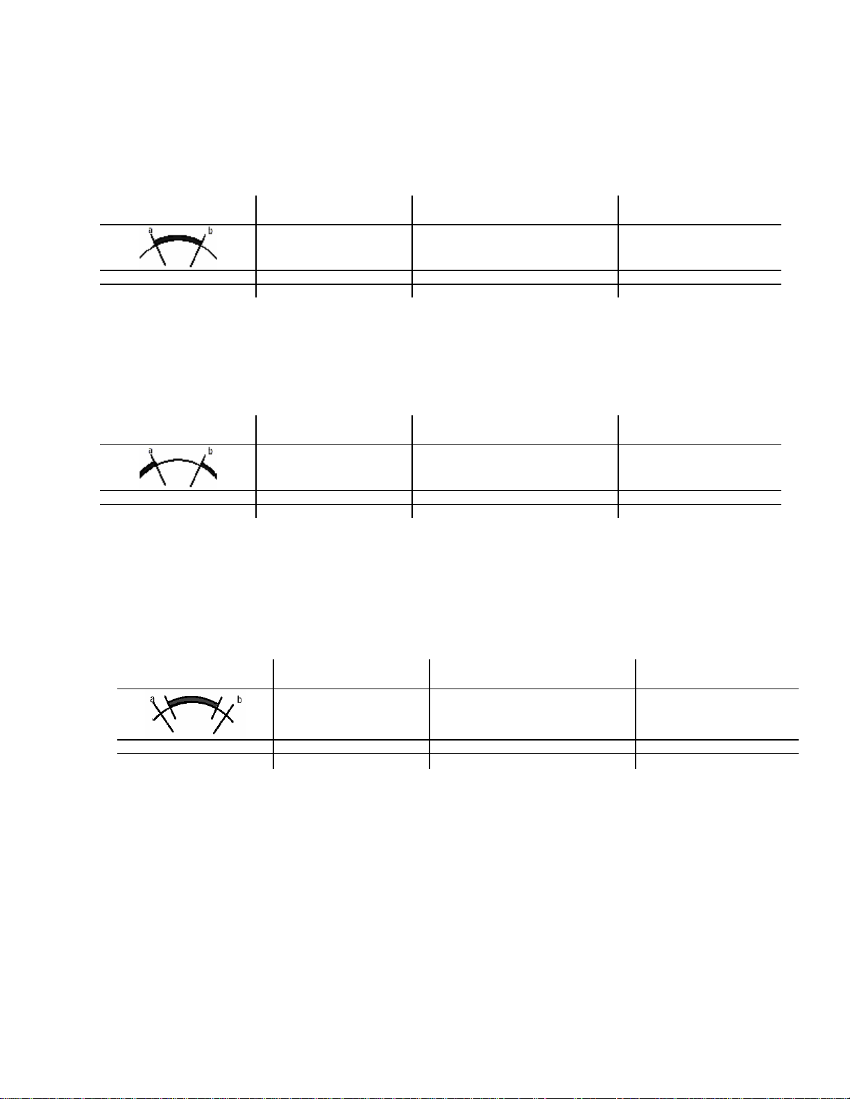
DEFINITION OF DIE MONITORING WINDOW
Window Input signals for Cyclic (CYC) and In-position (POS) modes are synchronized
with the rotation of the crankshaft, and must be detected within a zone of crankshaft
rotation. We call this zone a window. For example, a part-detect signal could be expected
within a window of 80-110º to indicate that a part was inside a die before it was hit by a
stroke.
When the software detects input signals that are different from those described here, the
software generates a fault signal. We graphically define these (window) inputs as follows:
DEFINITION OF DIE MONITORING WINDOW
Cyclic (CYC) N.O. Use this mode to verify that a pulse from the sensor (OFF-ON-OFF)
occurred within the window once each stroke. For example, use it to detect that a part
moved past a monitor.
Transition Diagram For These
Expected Transitions Input is NOT ALLOWED
When Sensor: Which Results in a
Fault Signal Sent After:
Sensor turns ON then OFF
within window 1. stays ON beyond window window goes OFF
2. turns ON outside window sensor turns ON
3. remains OFF for the cycle next window goes ON
Cyclic (CYC) N.C. Use this mode to verify that a pulse from the sensor (ON-OFF-ON)
occurred within the window once each stroke. For example, use it to detect that a part
moved past a monitor.
Transition Diagram For These
Expected Transitions Input is NOT ALLOWED
When Sensor: Which Results in a
Fault Signal Sent After:
Sensor turns OFF then ON
within window 1. stays OFF beyond window window goes OFF
2. turns OFF outside window sensor turns OFF
3. remains ON for the cycle next window goes OFF
HelmPak Press Control
11
Users Guide
In-position (POS) N.O. Use this mode to verify that the sensor signal remained ON
within the entire window once each stroke. The signal must cycle OFF outside the
window. Use it to detect if an ejector and other automation parts are retracted to home
position.
Transition Diagram For These
Expected Transitions Input is NOT ALLOWED
When the Sensor Signal: Which Results in a
Fault signal Sent After:
Sensor turns ON before,
and OFF after window 1. turns OFF before window goes OFF sensor turns OFF
2. does not turn OFF outside window next window goes ON
3. remains OFF for the cycle next window goes OFF
In-position (POS) N.C. Use this mode to verify that the sensor signal remained OFF
within the entire window once each stroke. The signal must cycle ON outside the window.
Use it to detect if an ejector and other automation parts are retracted to home position.
Transition Diagram For These
Expected Transitions Input is NOT ALLOWED
When the Sensor Signal: Which Results in a
Fault signal Sent After:
Sensor turns OFF before,
and ON after window 1. turns ON before window goes ON sensor turns ON
2. does not turn ON outside window next window goes OFF
3. remains ON for the cycle next window goes ON
DEFINITION OF DIE MONITORING WINDOW
Intermittent Cyclic (ICYC) Use this mode to verify that a pulse from the sensor (OFF-
ON-OFF) occurred within the window once after a preset number of press cycles.
Transition Diagram For These
Expected Transitions Input is NOT ALLOWED
When Sensor: Which Results in a
Fault Signal Sent After:
Sensor turns ON then OFF
within window 1. stays ON beyond window window goes OFF
2. turns ON outside window sensor turns ON
3. remains OFF for the cycle next window goes ON
DEFINITION OF DIE MONITORING WINDOW
Static Mode (STC) Use this mode to detect that an event occurred independent of the
press stroke. When a static-mode input turns Off, the programmed output is turned On.
For example, use it to detect end of stock.

HelmPak Press Control
12
Users Guide
OUTPUT RESPONSES FOR DIE MONITORING CHANNELS
When the software detects a channel fault, it displays the channel number and type of
fault on the Operator Interface screen. The software also sets a fault response that you
select from the following:
Warning (displays alarm banner on the active screen)
Top Stop
E-Stop
Output bypassed (no fault response)
HelmPak Press Control
13
Users Guide
SECTION 3:
BASIC OPERATING INSTRUCTIONS
•Turn power on
•Set CONTROL POWER to ON
•Press CONTROL POWER RESET, to reset the safety relay
•Start the Oil/Coolant pumps, button will turn green when all pumps running
•Set the press MODE selector switch to INCH mode
•Set the Main Motor selector switch to FORWARD
•Press Main Motor Start
•Verify that the current job/recipe matches the part being produced
•Set the press MODE selector switch: Inch, single, or Continuous
The Main Menu screen is the initial startup screen.
Fault conditions are indicated on the top of the screen in the alarm banner. Clear any
faults by pressing the FAULT RESET button on the operator station.
Press is ready to start – Refer to Mode of Operation
♦To EMERGENCY STOP the press push E-STOP
♦To stop the press in a non-emergency press TOP STOP

HelmPak Press Control
14
Users Guide
MODE OF OPERATION
Off Disable operation of clutch/brake control.
Inch Press and release both RUN buttons on side of
Operator Interface enclosure to inch slide. Hold
RUN buttons in and press will make one
complete cycle, stopping at the top of the cycle,
if inch stop on top is enabled
Single Stroke Press and hold RUN buttons for entire down
stroke of press, past 180. Press will stop at the
top of the cycle.
Continuous Run In this application Continuous is being used to
operate the press in a Single-On-Demand mode.
Press CONTINUOUS SETUP button. Press
both RUN buttons within 5 seconds of pressing
the CONTINUOUS SETUP button. Hold the
RUN buttons for the entire down stoke of the
first cycle. Release the RUN buttons on the
upstroke of the first cycle. The press should
now be operating in Single-On-Demand mode.
The press will stop at the top of the press stoke,
waiting for the robot to leave and initiate another
stroke. The press will wait at top for an amount
of time determined in the Job Recipe.
SHUT DOWN SYSTEM
To shut down the Helm-Pak:
•Stop the press
•Shut off Main Motor
•Shut Control Power off.
•Turn panel power off.
HelmPak Press Control
15
Users Guide
SECTION 4:
SCREEN NAVIGATION
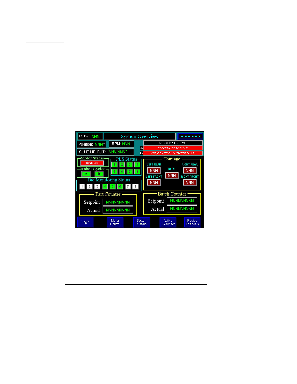
MAIN MENU
The MAIN SCREEN provides a display of pertinent information about the current run, including the
FAULT description when a machine stop occurs.
If recipe is incorporated into your system, the current job number is displayed. If shutheight monitoring is
installed, the current shutheight is displayed.
Entering a Preset
Most of the screens allow you to set a preset by touching the field for entry area on the screen. A data
entry field will pop up and you will use the numeric or alphanumeric keys to enter the value. Use the
ENTER key to store the value.
All Setup screens require a user to be logged in with sufficient privileges; this is done through the Login
Screen. Users can logout manually from the login screen or they will be automatically logged out after 30
minutes of no activity on the HMI.
By pressing on the various sections of the main menu, the user will be directed to that specific screen.
For example Tonnage will take the user to the main tonnage screen, Counters to counters screen, etc.
HelmPak Press Control
16
Users Guide
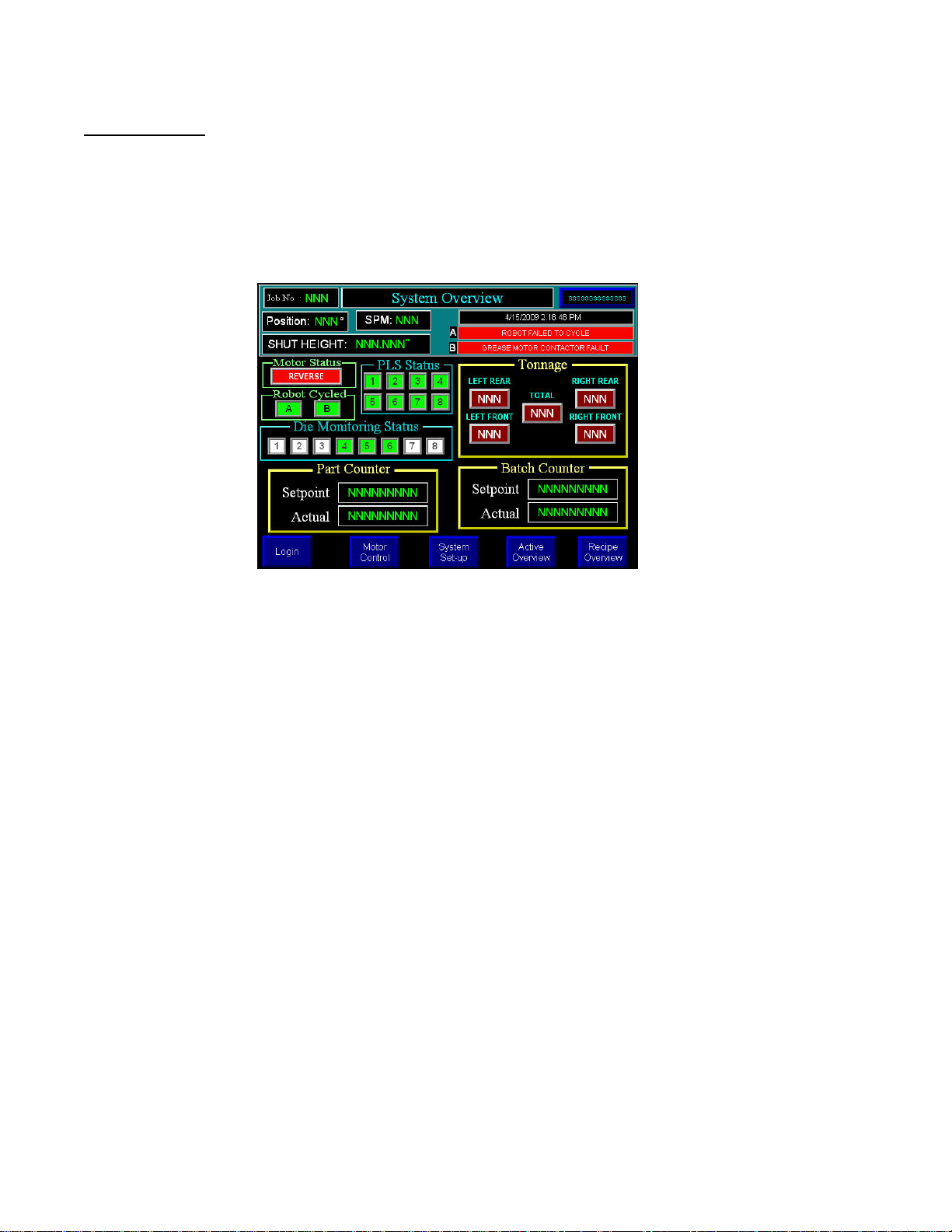
Login
Runtime Version – displays the current version of the HMI Application
Login – will bring up a user/password message, which will allow for value entry.
Logout – will log a user out and return the system to the “Default” user.
A user will automatically be logged out if there is no screen activity for 30 minutes.
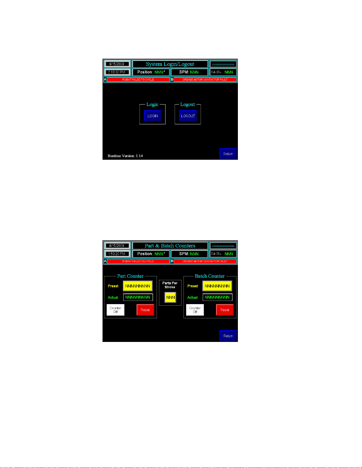
Counters
Parts Per Stroke – Identifies the number of parts each counter will be incremented by per press stroke
Counter: Preset – the value at which the count will continue to accumulate
Actual – the current value of the counter
Counter On/Off – enables the counter
Reset – Resets the Actual value

HelmPak Press Control
17
Users Guide
Motor Control
This screen allows the user to Start and Stop the Filter Motor, as well as displaying the current status of
the motor.

HelmPak Press Control
18
Users Guide
Tonnage Main
The 4 channels of Tonnage are all displayed individually, along with corresponding trending displays, and
the Total Tonnage.
The Monitor Parts/Peak Push Button Determines the mode of the Tonnage Module
Peak Mode – capacity alarms are active, trend alarms are inactive
Monitor Mode – both capacity and trend alarms are active
The Reverse Load Off/On Push Button Determines the mode of the Tonnage Module
Off – The module monitors standard load/force.
On – The module monitors the measurement of negative load/force being exerted on
machine following the break-through of material, also referred to as snap through.

HelmPak Press Control
19
Users Guide
Tonnage Alarms
High Capacity – displays the current High Capacity Alarm Setpoint.
These values are set for each channel and are typically established as press
capacity alarms. Each channel is typically set based on the formula:
Press Capacity divided by number of strain gage channels.
This value can be set lower that press capacity on each channel, but no
higher than 195% of scale factor.
High / Low Trend % - Displays the current Trend Percentage for the running tonnage
These values, set independently on each channel, are based on a percent of
allowable change from a sampled tonnage. This value can range from 1% to 99%. A
setting of 0% disables the trend alarms.

HelmPak Press Control
20
Users Guide
SECTION 5:
System Setup
On the main System Setup screen, the user has 5 entry options, 4 page buttons, and an exit to
configuration screen button. The Exit to Configuration screen button exits out of the current running
application, to the built in HMI interface.
Resolver Setup
This is used to calibrate the resolver input module during initial installation.
Move the crank position to 0 degrees and press Zero Resolver.
Calibrate the resolver input module in both PLC A & PLC B processors.
DM Inch Bypass
This buttons will allow Die Monitoring Inch Bypass to be enabled or disabled ( Enabled by Default)
Inch Stop On Top
This buttons will allow Inch Stop On Top to be enabled or disabled (disabled by Default)
Top Stop Setup
Run the press at maximum speed.
Enter the arbitrary number into the minimum angle. (350)
Run a Single stroke.
Add or subtract the top stop angle value to get an accurate top stop and enter that value into the top stop
angle. For instance if the press stops at 30°, Subtract 30 from the top stop and enter that value of
350(350-30=320). Enter 320 into the minimum angle.
Brake Monitor Setup
Shows the brake stop time in milliseconds and brake fault preset time, which is the amount of time in
milliseconds allowed before the system alarms on a brake fault time fault.
Table of contents


