Makita TW161D User manual

TW161D
EN Cordless Impact Wrench INSTRUCTION MANUAL 4
FR Boulonneuse sans Fil MANUEL D’ INSTRUCTIONS 10
DE Akku - Schlagschrauber BETRIEBSANLEITUNG 17
IT Avvitatrice ad impulso a
batteria ISTRUZIONI PER L’ USO 24
NL Accuslagmoersleutel GEBRUIKSAANWIJZING 31
ES Llave de Impacto Inalámbrica MANUAL DE
INSTRUCCIONES 38
PT Chave de Impacto a Bateria MANUAL DE INSTRUÇÕ ES 45
DA Elektronisk akku slagnøgle BRUGSANVISNING 52
EL Κρουστικό κλειδί μπαταρίας ΕΕΙΙΔΙ ΔΗΙΝ 58
TR Akülü Darbeli Somun Sıkma KULLANMA KILAVUZU 65

1
2
3
Fig.1
1
2
Fig.2
1
Fig.3
1
Fig.4
1
Fig.5
1
AB
Fig.6
4
1
2
3
5
Fig.7
1
23
Fig.8
2

2
3
1
Fig.9
1
4
2
3
Fig.10
3
2
1
Fig.11
Fig.12
3

4ENGLISH
ENGLISH (Original instructions)
SPECIFICATIONS
Model: TW161D
F astening c apac ities S tand ard bolt M8 - M1 6
H igh tensile bolt M6 - M1 2
S q uare d riv e 1 2.7 mm
No load speed H ard impac t mod e 0 - 2,4 00 min-1
S of t impac t mod e 0 - 1 ,300 min-1
I mpac ts per minute H ard impac t mod e 0 - 3,6 00 min-1
S of t impac t mod e 0 - 2,000 min-1
O v erall length 1 5 0 mm
R ated v oltage D .C . 1 0.8 V - 1 2 V max
Net w eigh t 1 .0 - 1 .2 kg
Due to our continuing program of research and development, the specications herein are subject to change
w ith out notic e.
Specications may differ from country to country.
The weight may differ depending on the attachment(s), including the battery cartridge. The lightest and heavi-
est c ombination, ac c ord ing to EP T A -P roc ed ure 01 / 201 4 , are sh ow n in th e table.
Applicable battery cartridge and charger
Battery cartridge BL 1 01 5 / BL 1 01 6 / BL 1 020B / BL 1 021 B / BL 1 04 0B / BL 1 04 1 B
C h arger D C 1 0S A / D C 1 0S B / D C 1 0W C / D C 1 0W D / D C 1 8 R E
Some of the battery cartridges and chargers listed above may not be available depending on your region of
resid enc e.
WARNING: Only use the battery cartridges and chargers listed above. Use of any other battery cartridges
and chargers may cause injury and/or re.
Intended use
T h e tool is intend ed f or f astening bolts and nuts.
Noise
The typical A-weighted noise level determined accord-
ing to EN6 28 4 1 -2-2:
Sound pressure level (LpA ) : dB(A)
Sound power level (LW A ) : dB (A)
Uncertainty (K) : dB(A)
NOTE: The declared noise emission value(s) has
been measured in ac c ord anc e w ith a stand ard test
method and may be used for comparing one tool with
anoth er.
NOTE: The declared noise emission value(s)
may also be used in a preliminary assessment of
ex posure.
WARNING: Wear ear protection.
WARNING:
The noise emission during actual
use of the power tool can differ from the declared val-
ue(s) depending on the ways in which the tool is used
especially what kind of workpiece is processed.
WARNING:
Be sure to identify safety measures
to protect the operator that are based on an estima-
tion of exposure in the actual conditions of use (tak-
ing account of all parts of the operating cycle such
as the times when the tool is switched off and when
it is running idle in addition to the trigger time).
Vibration
The vibration total value (tri-axial vector sum) deter-
mined ac c ord ing to EN6 28 4 1 -2-2:
W ork mod e: impac t tigh tening of f asteners of th e max i-
mum capacity of the tool
Vibration emission (ah) : . m/s2
Uncertainty (K) : . m/s2
NOTE: The declared vibration total value(s) has been
measured in ac c ord anc e w ith a stand ard test meth od
and may be used for comparing one tool with another.
NOTE: The declared vibration total value(s) may also
be used in a preliminary assessment of exposure.

5ENGLISH
WARNING:
The vibration emission during actual
use of the power tool can differ from the declared val-
ue(s) depending on the ways in which the tool is used
especially what kind of workpiece is processed.
WARNING:
Be sure to identify safety measures
to protect the operator that are based on an estima-
tion of exposure in the actual conditions of use (tak-
ing account of all parts of the operating cycle such
as the times when the tool is switched off and when
it is running idle in addition to the trigger time).
EC Declaration of Conformity
For European countries only
The EC declaration of conformity is included as Annex A
to th is instruc tion manual.
SAFETY WARNINGS
General power tool safety warnings
WARNING:
Read all safety warnings, instruc-
tions, illustrations and specications provided with this
power tool. F ailure to f ollow all instruc tions listed below
may result in electric shock, re and/or serious injury.
Save all warnings and instruc-
tions for future reference.
The term power tool in the warnings refers to your mains-oper-
ated (corded) power tool or battery-operated (cordless) power tool.
Cordless impact wrench safety warnings
1 .
Hold the power tool by insulated gripping surfaces,
when performing an operation where the fastener
may contact hidden wiring. F asteners c ontac ting a
live wire may make exposed metal parts of the power
tool " liv e" and c ould giv e th e operator an elec tric sh oc k.
2. Wear ear protectors.
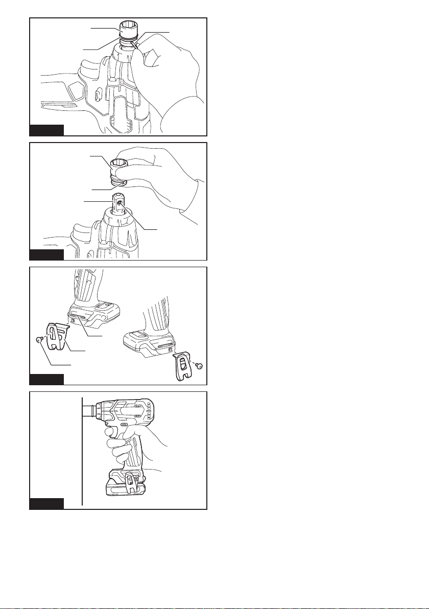
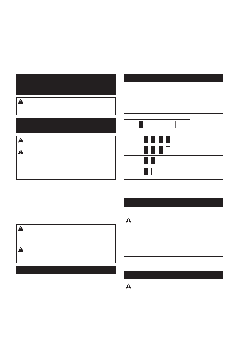
3. Check the impact socket carefully for wear,
cracks or damage before installation.
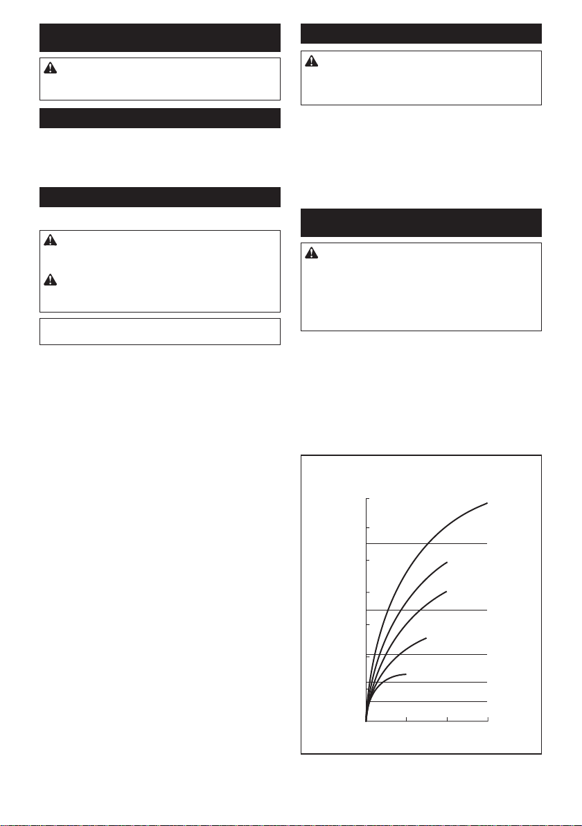
4 . Hold the tool rmly.
5 . Keep hands away from rotating parts.
6 . Do not touch the impact socket, bolt, nut or the
workpiece immediately after operation. They
may be extremely hot and could burn your skin.
7. Always be sure you have a rm footing.
Be sure no one is below when using the tool in
high locations.
8 . The proper fastening torque may differ
depending upon the kind or size of the bolt.
Check the torque with a torque wrench.
SAVE THESE INSTRUCTIONS.
WARNING:
DO NOT let comfort or familiarity
with product (gained from repeated use) replace strict
adherence to safety rules for the subject product.
MISUSE or failure to follow the safety rules stated in this
instruction manual may cause serious personal injury.
Important safety instructions for
battery cartridge
1 . Before using battery cartridge, read all instruc-
tions and cautionary markings on (1) battery
charger, (2) battery, and (3) product using
battery.
2. Do not disassemble battery cartridge.
3. If operating time has become excessively
shorter, stop operating immediately. It may
result in a risk of overheating, possible burns
and even an explosion.
4 . If electrolyte gets into your eyes, rinse them
out with clear water and seek medical atten-
tion right away. It may result in loss of your
eyesight.
5 . Do not short the battery cartridge:
() Do not touch the terminals with any con-
ductive material.
() Avoid storing battery cartridge in a con-
tainer with other metal objects such as
nails, coins, etc.
() Do not expose battery cartridge to water
or rain.
A battery short can cause a large current
ow, overheating, possible burns and even a
breakdown.
6 . Do not store the tool and battery cartridge in
locations where the temperature may reach or
exceed 50 ° C (122 ° F).
7. Do not incinerate the battery cartridge even if
it is severely damaged or is completely worn
out. The battery cartridge can explode in a re.
8 . Be careful not to drop or strike battery.
. Do not use a damaged battery.
1 0. The contained lithium-ion batteries are subject
to the Dangerous Goods Legislation require-
ments.
For commercial transports e.g. by third parties,
f orw ard ing agents, spec ial req uirement on pac k-
aging and labeling must be observ ed .
F or preparation of th e item being sh ipped , c onsult-
ing an ex pert f or h az ard ous material is req uired .
Please also observe possibly more detailed
national regulations.
T ape or mask of f open c ontac ts and pac k up th e
battery in such a manner that it cannot move
around in th e pac kaging.
1 1 . Follow your local regulations relating to dis-
posal of battery.
1 2. Use the batteries only with the products
specied by Makita. I nstalling th e batteries to
non-compliant products may result in a re, exces-
sive heat, explosion, or leak of electrolyte.
SAVE THESE INSTRUCTIONS.
CAUTION: Only use genuine Makita batteries.
U se of non-genuine Makita batteries, or batteries th at
have been altered, may result in the battery bursting
causing res, personal injury and damage. It will
also void the Makita warranty for the Makita tool and
c h arger.

6ENGLISH
Tips for maintaining maximum
battery life
1 .
Charge the battery cartridge before completely dis-
charged. Always stop tool operation and charge the
battery cartridge when you notice less tool power.
2.
Never recharge a fully charged battery cartridge.
Overcharging shortens the battery service life.
3.
Charge the battery cartridge with room tempera-
ture at 10 ° C - 40 ° C (50 ° F - 104 ° F). Let a hot
battery cartridge cool down before charging it.
FUNCTIONAL
DESCRIPTION
CAUTION: Always be sure that the tool is
switched off and the battery cartridge is removed
before adjusting or checking function on the tool.
Installing or removing battery
cartridge
CAUTION: Always switch off the tool before
installing or removing of the battery cartridge.
CAUTION: Hold the tool and the battery car-
tridge rmly when installing or removing battery
cartridge. Failure to hold the tool and the battery
cartridge rmly may cause them to slip off your hands
and result in damage to the tool and battery cartridge
and a personal injury.
Fig.1: 1. R ed ind ic ator 2. Button 3. Battery cartridge
To remove the battery cartridge, slide it from the tool
w h ile slid ing th e button on th e f ront of th e c artrid ge.
To install the battery cartridge, align the tongue on the
battery cartridge with the groove in the housing and slip
it into place. Insert it all the way until it locks in place
with a little click. If you can see the red indicator on the
upper side of the button, it is not locked completely.
CAUTION: Always install the battery cartridge
fully until the red indicator cannot be seen. I f not,
it may accidentally fall out of the tool, causing injury to
you or someone around you.
CAUTION: Do not install the battery cartridge
forcibly. If the cartridge does not slide in easily, it is
not being inserted correctly.
Battery protection system
The tool is equipped with a battery protection system.
This system automatically cuts off power to the motor to
extend battery life.
The tool will automatically stop during operation if the
tool and/or battery are placed under one of the following
c ond itions:
Overloaded:
T h e tool is operated in a manner th at c auses it to d raw
an abnormally high current.
I n th is situation, turn th e tool of f and stop th e applic ation
th at c aused th e tool to bec ome ov erload ed . T h en turn
th e tool on to restart.
If the tool does not start, the battery is overheated. In this
situation, let the battery cool before turning the tool on again.
Low battery voltage:
The remaining battery capacity is too low and the tool
will not operate. If you turn the tool on, the motor runs
again but stops soon. I n th is situation, remov e and
recharge the battery.
Indicating the remaining battery capacity
Only for battery cartridges with the indicator
Fig.2: 1. I nd ic ator lamps 2. C h ec k button
Press the check button on the battery cartridge to indi-
cate the remaining battery capacity. The indicator lamps
ligh t up f or a f ew sec ond s.
Indicator lamps Remaining
capacity
Lighted Off
75 % to 1 00%
5 0% to 75 %
25 % to 5 0%
0% to 25 %
NOTE: D epend ing on th e c ond itions of use and th e
ambient temperature, the indication may differ slightly
from the actual capacity.
Switch action
Fig.3: 1. S w itc h trigger
CAUTION: Before installing the battery car-
tridge into the tool, always check to see that the
switch trigger actuates properly and returns to
the " OFF" position when released.
To start the tool, simply pull the switch trigger. Tool
speed is increased by increasing pressure on the switch
trigger. R elease th e sw itc h trigger to stop.
NOTE: The tool automatically stops if you keep pull-
ing th e sw itc h trigger f or about 6 minutes.
Lighting up the front lamp
CAUTION: Do not look in the light or see the
source of light directly.
Fig.4: 1. L amp
Fig.5: 1. Button
P ull th e sw itc h trigger to turn on th e lamp. T o turn of f ,
release it. The lamp goes out approximately seconds
af ter releasing th e sw itc h trigger.

7ENGLISH
T o keep th e lamp of f , turn of f th e lamp status. F irst pull
and release th e sw itc h trigger.A nd th en press th e but-
ton f or one sec ond w ith in 1 0 sec ond s.
T o turn on th e lamp status again, press th e button again
similarly.
NOTE: To conrm the lamp status, pull the trigger.
When the lamp lights up by pulling the switch trigger,
th e lamp status is O N. W h en th e lamp d oes not c ome
on, th e lamp status is O F F .
NOTE: When the tool is overheated, the light ashes
for one minute, and then the LED display goes off. In
th is c ase, c ool d ow n th e tool bef ore operating again.
NOTE: Use a dry cloth to wipe the dirt off the lens of
th e lamp. Be c aref ul not to sc ratc h th e lens of lamp, or
it may lower the illumination.
Reversing switch action
Fig.6: 1. R ev ersing sw itc h lev er
CAUTION: Always check the direction of
rotation before operation.
CAUTION: Use the reversing switch only after
the tool comes to a complete stop. C h anging th e
direction of rotation before the tool stops may dam-
age th e tool.
CAUTION: When not operating the tool,
always set the reversing switch lever to the neu-
tral position.
T h is tool h as a rev ersing sw itc h to c h ange th e d irec tion
of rotation. D epress th e rev ersing sw itc h lev er f rom th e
A sid e f or c loc kw ise rotation or f rom th e B sid e f or c oun-
terc loc kw ise rotation.
W h en th e rev ersing sw itc h lev er is in th e neutral posi-
tion, th e sw itc h trigger c annot be pulled .
Changing the impact force
Fig.7: 1. H ard 2. S of t 3. R ev erse rotation auto stop
mod e 4. C h anged in th ree steps 5. Button Y ou c an c h ange th e impac t f orc e in th ree steps: h ard ,
sof t, and R ev erse rotation auto stop mod e.
T h is allow s a tigh tening suitable to th e w ork.
Every time the button is pressed, the number of blows
c h anges in th ree steps.
The function of Reverse rotation auto stop mode works only with pulling the trigger fully in counterclockwise tool
rotation. W h en th e bolt/ nut gets enough loosened , th e tool stops th e impac t and rotation.
For approximately one minute after releasing the switch trigger, the impact force can be changed.
Impact force grade displayed
on panel Maximum blows Purpose Example of application
H ard 3,6 00 min-1 (/min) T igh tening w h en f orc e and
speed are d esired . A ssembling steel f rames.
S of t 2,000 min-1 (/min) Tightening when you need ne
adjustment with small diameter
bolt.
A ssembling f urniture.
R ev erse rotation auto stop
mod e 3,6 00 min-1 (/min) L oosening w ith auto stop
f unc tion. D isassembling bolts/ nuts.
NOTE: Reverse rotation auto stop mode is available only when the tool rotates counterclockwise. When rotating
c loc kw ise in R ev erse rotation auto stop mod e, th e impac t f orc e and speed are th e same as H ard impac t mod e.
NOTE: When all lamps on the switch panel go out, the tool is turned off to save the battery power. The impact force
grade can be checked by pulling the switch trigger to the extent that the tool does not operate.
NOTE: W h ile pulling th e sw itc h trigger, th e impac t f orc e grad e c annot be c h anged .

8ENGLISH
ASSEMBLY
CAUTION: Always be sure that the tool is
switched off and the battery cartridge is removed
before carrying out any work on the tool.
Selecting correct impact socket
Always use the correct size impact socket for bolts and
nuts.A n inc orrec t siz e impac t soc ket w ill result in inac -
c urate and inc onsistent f astening torq ue and / or d amage
to th e bolt or nut.
Installing or removing impact socket
Optional accessory
CAUTION: Make sure that the impact socket
and the mounting portion are not damaged before
installing the impact socket.
CAUTION: After inserting the impact socket,
make sure that it is rmly secured. If it comes out,
do not use it.
NOTE: The way of impact socket installation varies
depending on the type of the square drive on the tool.
Tool with the ring spring
For impact socket without O-ring and pin
Fig.8: 1. I mpac t soc ket 2. S q uare d riv e 3. R ing
spring
P ush th e impac t soc ket onto th e sq uare d riv e until it
loc ks into plac e.
To remove the impact socket, simply pull it off.
For impact socket with O-ring and pin
Fig.9 : 1. I mpac t soc ket 2. O -ring 3. P in
Mov e th e O -ring out of th e groov e in th e impac t soc ket
and remov e th e pin f rom th e impac t soc ket. F it th e
impac t soc ket onto th e sq uare d riv e so th at th e h ole in
th e impac t soc ket is aligned w ith th e h ole in th e sq uare
d riv e.
I nsert th e pin th rough th e h ole in th e impac t soc ket and
sq uare d riv e. T h en return th e O -ring to th e original posi-
tion in th e impac t soc ket groov e to retain th e pin.
T o remov e th e impac t soc ket, f ollow th e installation
proc ed ures in rev erse.
Tool with the detent pin
Fig.10: 1. I mpac t soc ket 2. H ole 3. S q uare d riv e
4. D etent pin
A lign th e h ole in th e sid e of th e impac t soc ket w ith th e
d etent pin on th e sq uare d riv e and push th e impac t
soc ket onto th e sq uare d riv e until it loc ks into plac e. T ap
it lightly if required.
To remove the impact socket, simply pull it off. If it is
h ard to remov e, d epress th e d etent pin w h ile pulling th e
impac t soc ket.
Installing hook
CAUTION: When installing the hook, always
secure it with the screw rmly. I f not, th e h ook
may come off from the tool and result in the personal
injury.
Fig.11: 1. G roov e 2. H ook 3. S c rew
The hook is convenient for temporarily hanging the tool.
T h is c an be installed on eith er sid e of th e tool. T o install
th e h ook, insert it into a groov e in th e tool h ousing on
eith er sid e and th en sec ure it w ith a sc rew . T o remov e,
loosen th e sc rew and th en take it out.
OPERATION
CAUTION: Always insert the battery cartridge
all the way until it locks in place. If you can see the
red ind ic ator on th e upper sid e of th e button, it is not
locked completely. Insert it fully until the red indicator
cannot be seen. If not, it may accidentally fall out of
the tool, causing injury to you or someone around
you.
Fig.12
Hold the tool rmly and place the impact socket over
th e bolt or nut. T urn th e tool on and f asten f or th e proper
f astening time.
The proper fastening torque may differ depending upon
th e kind or siz e of th e bolt, th e material of th e w orkpiec e
to be f astened , etc . T h e relation betw een f astening
torque and fastening time is shown in the gures.
Proper fastening torque for standard bolt
N•m
(kgf•cm)
2
1
2
13
0
100
(1020)
120
(1224)
80
(816)
60
(612)
40
(408)
20
(204)
M12
M14
M10
M12
M14
M10
M8
M8
140
(1430)
M16
M16
1. Fastening time (second) 2. F astening torq ue

9ENGLISH
Proper fastening torque for high tensile bolt
2
1
140
(1430)
N•m
(kgf•cm)
210
80
(816)
60
(612)
40
(408)
20
(204)
3
100
(1020)
120
(1224)
M10
M12
M12
M8
M8
M10
1. Fastening time (second) 2. F astening torq ue
NOTE: H old th e tool pointed straigh t at th e bolt or nut.
NOTE: Excessive fastening torque may damage the
bolt/nut or impact socket. Before starting your job,
always perform a test operation to determine the
proper fastening time for your bolt or nut.
NOTE: If the tool is operated continuously until the
battery cartridge has discharged, allow the tool to rest
for minutes before proceeding with a fresh battery
c artrid ge.
The fastening torque is affected by a wide variety of
factors including the following. After fastening, always
c h ec k th e torq ue w ith a torq ue w renc h .
. When the battery cartridge is discharged almost
completely, voltage will drop and the fastening
torq ue w ill be red uc ed .
2. I mpac t soc ket
• F ailure to use th e c orrec t siz e impac t soc ket
w ill c ause a red uc tion in th e f astening torq ue.
•
A worn impact socket (wear on the hex end or square
end) will cause a reduction in the fastening torque.
3. Bolt
•
Even though the torque coefcient and the class
of bolt are th e same, th e proper f astening torq ue
w ill d if f er ac c ord ing to th e d iameter of bolt.
•
Ev en th ough th e d iameters of bolts are th e same, th e
proper f astening torq ue w ill d if f er ac c ord ing to th e
torque coefcient, the class of bolt and the bolt length.
4 .
The use of the universal joint or the extension bar some-
w h at red uc es th e f astening f orc e of th e impac t w renc h .
Compensate by fastening for a longer period of time.
5 .
T h e manner of h old ing th e tool or th e material of
d riv ing position to be f astened w ill af f ec t th e torq ue.
6 . O perating th e tool at low speed w ill c ause a red uc -
tion in th e f astening torq ue.
MAINTENANCE
CAUTION: Always be sure that the tool is
switched off and the battery cartridge is removed
before attempting to perform inspection or
maintenance.
NOTICE: Never use gasoline, benzine, thinner,
alcohol or the like. Discoloration, deformation or
cracks may result.
T o maintain prod uc t S A F ET Y and R EL I A BI L I T Y ,
repairs, any other maintenance or adjustment should
be performed by Makita Authorized or Factory Service
Centers, always using Makita replacement parts.
OPTIONAL
ACCESSORIES
CAUTION: These accessories or attachments
are recommended for use with your Makita tool
specied in this manual. The use of any other
ac c essories or attac h ments migh t present a risk of
injury to persons. Only use accessory or attachment
f or its stated purpose.
If you need any assistance for more details regard-
ing these accessories, ask your local Makita Service
C enter.
• I mpac t soc ket
• H ook
• Ex tension bar
Universal joint
• S oc ket bit ad apter
Plastic carrying case
Makita genuine battery and charger
NOTE: Some items in the list may be included in the
tool package as standard accessories. They may
differ from country to country.

10 FRANÇAIS
FRANÇAIS (Instructions originales)
SPÉ CIFICATIONS
Modè le : TW161D
C apac ité s d e serrage Boulon stand ard M8 - M1 6
Boulon à h aute ré sistanc e M6 - M1 2
C arré c ond uc teur 1 2,7 mm
Vitesse à v id e Mod e d e perc ussion rud e 0 - 2 4 00 min-1
Mod e d e perc ussion d ouc e 0 - 1 300 min-1
C oups par minute Mod e d e perc ussion rud e 0 - 3 6 00 min-1
Mod e d e perc ussion d ouc e 0 - 2 000 min-1
L ongueur totale 1 5 0 mm
T ension nominale 1 0,8 V - 1 2 V C C max .
P oid s net 1 ,0 - 1 ,2 kg
tant donné l’évolution constante de notre programme de recherche et de développement, les spécications
contenues dans ce manuel sont sujettes à modication sans préavis.
Les spécications peuvent varier suivant les pays.
• L e poid s peut ê tre d if f é rent selon les ac c essoires, notamment la batterie. L es assoc iations la plus lé gè re et la
plus lourd e, c onf ormé ment à la proc é d ure EP T A 01 / 201 4 , sont ind iq ué es d ans le tableau.
Batterie et chargeur applicables
Batterie BL 1 01 5 / BL 1 01 6 / BL 1 020B / BL 1 021 B / BL 1 04 0B / BL 1 04 1 B
C h argeur D C 1 0S A / D C 1 0S B / D C 1 0W C / D C 1 0W D / D C 1 8 R E
• C ertains c h argeurs et batteries ré pertorié s c i-d essus peuv ent ne pas ê tre d isponibles selon la ré gion où v ous
ré sid ez .
AVERTISSEMENT : N’ utilisez que les batteries et les chargeurs répertoriés ci-dessus. L ’ utilisation
d ’ autres batteries et c h argeurs peut prov oq uer d es blessures et/ ou un inc end ie.
Utilisations
L’outil est conçu pour la xation des boulons et des
é c rous.
Bruit
Niveau de bruit pondéré A typique, déterminé selon
EN6 28 4 1 -2-2 :
Niveau de pression sonore (LpA ) : dB (A)
Niveau de puissance sonore (LW A ) : dB (A)
Incertitude (K) : dB (A)
NOTE : L a ou les v aleurs d ’ é mission d e bruit d é c la-
ré es ont é té mesuré es c onf ormé ment à la mé th od e
d e test stand ard et peuv ent ê tre utilisé es pour c om-
parer les outils entre eux .
NOTE : L a ou les v aleurs d ’ é mission d e bruit d é c la-
ré es peuv ent aussi ê tre utilisé es pour l’ é v aluation
pré liminaire d e l’ ex position.
AVERTISSEMENT : Portez un serre-tê te
antibruit.
AVERTISSEMENT : L’ émission de bruit
lors de l’ usage réel de l’ outil électrique peut ê tre
différente de la ou des valeurs déclarées, suivant
la façon dont l’ outil est utilisé, particuliè rement
selon le type de piè ce usinée.
AVERTISSEMENT : Les mesures de sécurité
à prendre pour protéger l’ utilisateur doivent ê tre
basées sur une estimation de l’ exposition dans
des conditions réelles d’ utilisation (en tenant
compte de toutes les composantes du cycle
d’ utilisation, comme par exemple le moment de
sa mise hors tension, lorsqu’ il tourne à vide et le
moment de son déclenchement).
Vibrations
Valeur totale de vibrations (somme de vecteur triaxial)
d é terminé e selon EN6 28 4 1 -2-2 :
Mod e d e trav ail : serrage av ec impac t d e v is ou boulon
ne d é passant pas la c apac ité max imale d e l’ outil
mission de vibrations (ah) : , m/s2
Incertitude (K) : , m/s2

11 FRANÇAIS
NOTE : L a ou les v aleurs d e v ibration totales d é c la-
ré es ont é té mesuré es c onf ormé ment à la mé th od e
d e test stand ard et peuv ent ê tre utilisé es pour c om-
parer les outils entre eux .
NOTE : L a ou les v aleurs d e v ibration totales d é c la-
ré es peuv ent aussi ê tre utilisé es pour l’ é v aluation
pré liminaire d e l’ ex position.
AVERTISSEMENT : L’ émission de vibrations
lors de l’ usage réel de l’ outil électrique peut ê tre
différente de la ou des valeurs déclarées, suivant
la façon dont l’ outil est utilisé, particuliè rement
selon le type de piè ce usinée.
AVERTISSEMENT : Les mesures de sécurité
à prendre pour protéger l’ utilisateur doivent ê tre
basées sur une estimation de l’ exposition dans
des conditions réelles d’ utilisation (en tenant
compte de toutes les composantes du cycle
d’ utilisation, comme par exemple le moment de
sa mise hors tension, lorsqu’ il tourne à vide et le
moment de son déclenchement).
Déclaration de conformité CE
Pour les pays européens uniquement
L a d é c laration d e c onf ormité C E est f ournie en A nnex e
A à c e mod e d ’ emploi.
CONSIGNES DE SÉ CURITÉ
Consignes de sécurité générales
pour outils électriques
AVERTISSEMENT : Veuillez lire les
consignes de sécurité, instructions, illustrations
et spécications ui accompagnent cet outil
électrique. L e non-respec t d e toutes les instruc tions
ind iq ué es c i-d essous peut entraî ner une é lec troc u-
tion, un inc end ie et/ ou d e grav es blessures.
Conservez toutes les mises en
garde et instructions pour réfé-
rence ultérieure.
L e terme « outil é lec triq ue » d ans les av ertissements
f ait ré f é renc e à l’ outil é lec triq ue alimenté par le sec teur
(avec cordon d’alimentation) ou à l’outil électrique fonc-
tionnant sur batterie (sans cordon d’alimentation).
Consignes de sécurité pour
boulonneuse sans l
1 . Tenez l’ outil électrique par des surfaces de
prise isolées lorsque vous effectuez une tâ che
au cours de laquelle la vis ou le boulon peut
entrer en contact avec des ls cachés. L e
contact de la vis ou du boulon avec un l sous ten-
sion peut transmettre d u c ourant d ans les piè c es
mé talliq ues ex posé es d e l’ outil et é lec troc uter
l’ opé rateur.
2. Portez un casque anti-bruit.
3. Vériez ue la douille choc nest pas usée,
ssurée ou endommagée avant linstallation.
4 . Tenez votre outil fermement.
5 . Gardez les mains éloignées des piè ces en
rotation.
6 . Ne touchez pas la douille à choc, le boulon,
l’ écrou ou la piè ce immédiatement aprè s le
fonctionnement. I ls pourraient ê tre ex trê mement
c h aud s et v ous brû ler la peau.
7. Ayez toujours une assise ferme sous vos
pieds.
Veillez à ce que personne ne se trouve en
dessous de vous quand vous utilisez l’ outil en
hauteur.
8 . Le couple de serrage correct peut varier
en fonction du type ou de la dimension du
boulon. Vériez le couple laide dune clé
dynamométrique.
CONSERVEZ CES
INSTRUCTIONS.
AVERTISSEMENT : NE vous laissez PAS
tromper (au l dune utilisation répétée) par un
sentiment d’ aisance et de familiarité avec le
produit, en négligeant le respect rigoureux des
consignes de sécurité qui accompagnent le pro-
duit en question.
La MAUVAISE UTILISATION de l’ outil ou l’ igno-
rance des consignes de sécurité indiquées
dans ce mode d’ emploi peut entraî ner de graves
blessures.
Consignes de sécurité importantes
pour la batterie
1 . Avant d’ utiliser la batterie, lisez toutes les
instructions et précautions relatives (1) au
chargeur de batterie, (2) à la batterie, et (3) au
produit utilisant la batterie.
2. Ne démontez pas la batterie.
3. Cessez immédiatement l’ utilisation si le temps
de fonctionnement devient excessivement
court. Il y a risque de surchauffe, de brû lures,
voire d’ explosion.
4 . Si l’ électrolyte pénè tre dans vos yeux, rin-
cez-les à l’ eau claire et consultez immédiate-
ment un médecin. Il y a risque de perte de la
vue.
5 . Ne court-circuitez pas la batterie :
() Ne touchez les bornes avec aucun maté-
riau conducteur.
() É vitez de ranger la batterie dans un
conteneur avec d’ autres objets métal-
liques, par exemple des clous, des piè ces
de monnaie, etc.
() N’ exposez pas la batterie à l’ eau ou à la
pluie.
Un court-circuit de la batterie peut provoquer
une intensité de courant élevée, une sur-
chauffe, parfois des brû lures et mê me une
panne.

12 FRANÇAIS
6 . Ne rangez pas l’ outil et la batterie dans un
endroit où la température risque d’ atteindre ou
de dépasser 50 ° C.
7. Ne jetez pas la batterie au feu mê me si elle est
sérieusement endommagée ou complè tement
épuisée. La batterie peut exploser au contact
du feu.
8 . É vitez de laisser tomber ou de cogner la
batterie.
. N’ utilisez pas la batterie si elle est
endommagée.
1 0. Les batteries au lithium-ion contenues sont
soumises aux exigences de la législation sur
les marchandises dangereuses.
L ors d u transport c ommerc ial par d es tierc es
parties ou d es transitaires par ex emple, d es ex i-
gences spéciques en matière d’étiquetage et
d ’ emballage d oiv ent ê tre respec té es.
P our la pré paration d e l’ artic le ex pé d ié , il est
né c essaire d e c onsulter un ex pert en maté riau
d angereux . Veuillez é galement respec ter les
ré glementations nationales susc eptibles d ’ ê tre
plus d é taillé es.
R ec ouv rez les c ontac ts ex posé s av ec d u ruban
ad h é sif ou d u ruban d e masq uage et emballez la
batterie d e telle sorte q u’ elle ne puisse pas bouger
d ans l’ emballage.
1 1 . Suivez les réglementations locales en matiè re
de mise au rebut des batteries.
1 2. Utilisez les batteries uniquement avec les
produits spéciés par Makita. L ’ insertion d e
batteries d ans d es prod uits non c onf ormes peut
prov oq uer un inc end ie, une c h aleur ex c essiv e,
une explosion ou une fuite de l’électrolyte.
CONSERVEZ CES
INSTRUCTIONS.
ATTENTION : N’ utilisez que des batteries
Makita d’ origine. L ’ utilisation d e batteries d e marq ue
autre que Makita ou de batteries modiées peut pro-
v oq uer l’ ex plosion d es batteries, c e q ui pré sente un
risq ue d ’ inc end ie, d e d ommages maté riels et c orpo-
rels. C ela annulera é galement la garantie Makita pour
l’ outil et le c h argeur Makita.
Conseils pour assurer la durée
de vie optimale de la batterie
1 . Chargez la batterie avant qu’ elle ne soit com-
plè tement déchargée. Arrê tez toujours l’ outil
et rechargez la batterie quand vous remarquez
que la puissance de l’ outil diminue.
2. Ne rechargez jamais une batterie complè te-
ment chargée. La surcharge réduit la durée de
service de la batterie.
3. Chargez la batterie à une température
ambiante comprise entre 10 ° C et 40 ° C. Avant
de charger une batterie chaude, laissez-la
refroidir.
DESCRIPTION DU
FONCTIONNEMENT
ATTENTION : Assurez-vous toujours que
l’ outil est hors tension et que sa batterie est
retirée avant de lajuster ou de vérier son
fonctionnement.
Insertion ou retrait de la batterie
ATTENTION : É teignez toujours l’ outil avant
de mettre en place ou de retirer la batterie.
ATTENTION : Tenez fermement l’ outil et la
batterie lors de la mise en place ou du retrait de
la batterie. S i v ous ne tenez pas f ermement l’ outil
et la batterie, ils peuv ent v ous glisser d es mains, et
s’ abî mer ou v ous blesser.
Fig.1: 1. Voyant rouge 2. Bouton 3. Batterie
P our retirer la batterie, f aites-la glisser h ors d e l’ outil
tout en f aisant glisser le bouton à l’ av ant d e la batterie.
P our mettre en plac e la batterie, alignez la languette sur
la batterie av ec la rainure sur le c ompartiment et insé -
rez-la. Insérez-la à fond jusqu’à ce qu’un léger déclic
se fasse entendre. Si le voyant rouge sur le dessus du
bouton est visible, cela signie qu’elle n’est pas bien
v errouillé e.
ATTENTION : Insérez toujours complè tement
la batterie jusqu’ à ce que le voyant rouge ne soit
plus visible. S inon, elle pourrait tomber ac c id en-
tellement d e l’ outil, au risq ue d e v ous blesser ou d e
blesser q uelq u’ un se trouv ant prè s d e v ous.
ATTENTION : N’ insérez pas la batterie de
force. S i elle ne glisse pas f ac ilement, c ’ est q ue v ous
ne l’ insé rez pas c orrec tement.
Systè me de protection de la batterie
L’outil est équipé d’un système de protection de la
batterie. Ce système coupe automatiquement le cou-
rant d e l’ outil pour prolonger la d uré e d e serv ic e d e la
batterie.
L ’ outil s’arrê tera automatiq uement en c ours d ’ utilisation
si l’ outil et/ ou la batterie se trouv e d ans l’ une ou l’ autre
d es situations suiv antes :
Surcharge :
L ’ outil est utilisé d e maniè re telle q u’ il c onsomme un
c ourant anormalement é lev é .
Dans ce cas, éteignez l’outil et arrtez la tche ayant
prov oq ué la surc h arge d e l’ outil. P uis rallumez l’ outil
pour reprend re la tâ c h e.
S i l’ outil ne d é marre pas, c ’ est q ue la batterie a sur-
c h auf f é . D ans c e c as, laissez la batterie ref roid ir av ant
d e rallumer l’ outil.
Faible tension de la batterie :
L a c h arge restante d e la batterie est trop f aible et l’outil
ne f onc tionne pas. S i v ous mettez l’outil sous tension,
le moteur red é marre, mais s’ arrê te rapid ement. L e c as
é c h é ant, retirez et rec h argez la batterie.

13 FRANÇAIS
Indication de la charge restante de
la batterie
Uniquement pour les batteries avec voyant
lumineux
Fig.2: 1. T é moins 2. Bouton de vérication
Appuyez sur le bouton de vérication sur la batterie
pour ind iq uer la c h arge restante d e la batterie. L es
té moins s’ allument pend ant q uelq ues sec ond es.
Témoins Charge
restante
Allumé É teint
75 % à 1 00 %
5 0 % à 75 %
25 % à 5 0 %
0 % à 25 %
NOTE : S elon les c ond itions d ’ utilisation et la tem-
pé rature ambiante, l’ ind ic ation peut ê tre lé gè rement
d if f é rente d e la c apac ité ré elle.
Fonctionnement de la gâ chette
Fig.3: 1. G â c h ette
ATTENTION : Avant d’ insérer la batterie dans
loutil, vériez toujours ue la gchette fonc-
tionne bien et revient en position d’ arrê t lorsque
vous la relâ chez.
Il suft d’enclencher la gchette pour démarrer l’outil.
L a v itesse d e l’ outil augmente à mesure q ue l’ on ac c roî t
la pression ex erc é e sur la gâ c h ette. P our l’ arrê ter,
relâ c h ez la gâ c h ette.
NOTE : L ’ outil s’arrê tera automatiq uement si v ous
c ontinuez d ’ enc lenc h er la gâ c h ette pend ant 6
minutes env iron.
Allumage de la lampe avant
ATTENTION : É vitez de regarder directement
le faisceau lumineux ou sa source.
Fig.4: 1. L ampe
Fig.5: 1. Bouton
Enc lenc h ez la gâ c h ette pour allumer la lampe.
R elâ c h ez -la pour l’ é teind re. L a lampe s’ é teint env iron
1 0 sec ond es aprè s av oir relâ c h é la gâ c h ette.
P our maintenir la lampe é teinte, d é sac tiv ez le statut
d e la lampe. C ommenc ez par enc lenc h er et relâ c h er la
gchette. Appuyez ensuite sur le bouton pend ant
une sec ond e d ans les 1 0 sec ond es.
Pour réactiver le statut de la lampe, appuyez à nouveau
d e la mê me maniè re sur le bouton.
NOTE : Pour vérier si la lampe est activée ou désac-
tiv é e, enc lenc h ez la gâ c h ette. S i la lampe s’ allume
lorsque vous enclenchez la gchette, cela signie
q u’ elle est ac tiv é e. S i la lampe ne s’ allume pas, c ela
signie qu’elle est désactivée.
NOTE : En c as d e surc h auf f e d e l’ outil, la lumiè re
clignote pendant une minute, puis l’afcheur à DEL
s’ é teint. I l f aut alors laisser ref roid ir l’ outil av ant d e le
remettre en marc h e.
NOTE : R etirez la saleté sur la lentille d e la lampe
avec un chiffon sec. Prenez soin de ne pas éraer
la lentille d e la lampe sous peine d e d iminuer son
é c lairage.
Fonctionnement de l’ inverseur
Fig.6: 1. L ev ier d e l’ inv erseur
ATTENTION : Vériez toujours le sens de
rotation avant d’ utiliser l’ outil.
ATTENTION : N’ utilisez l’ inverseur qu’ une
fois que l’ outil est complè tement arrê té. S i v ous
c h angez le sens d e rotation av ant l’ arrê t d e l’ outil,
v ous risq uez d e l’ end ommager.
ATTENTION : Lorsque vous n’ utilisez pas
l’ outil, placez toujours le levier de l’ inverseur en
position neutre.
L ’ outil possè d e un inv erseur q ui permet d e c h anger
le sens d e rotation. Enf onc ez le lev ier d e l’ inv erseur
d u c ô té A pour une rotation d ans le sens d es aiguilles
d ’ une montre, ou d u c ô té B pour une rotation d ans le
sens inv erse d es aiguilles d ’ une montre.
L a gâ c h ette ne peut pas ê tre enc lenc h é e lorsq ue le
lev ier d e l’ inv erseur se trouv e en position neutre.

14 FRANÇAIS
Changement de la force du choc
Fig.7: 1. P uissant 2. F aible 3. Mod e d ’ arrê t automa-
tiq ue en rotation arriè re 4. Modié selon trois
niv eaux 5. Bouton
Vous pouvez modier la force de percussion selon trois niveaux :
puissant, f aible et mod e d ’arrê t automatiq ue en rotation arriè re.
Ceci vous permet d’obtenir un serrage adapté au type de travail.
C h aq ue f ois q ue le bouton est enf onc é , le nombre d e
c oups c h ange selon trois niv eaux .
L e mod e d ’ arrê t automatiq ue en rotation arriè re f onc tionne uniq uement si v ous enc lenc h ez à f ond la gâ c h ette av ec
l’ outil tournant d ans le sens inv erse d es aiguilles d ’ une montre. U ne f ois q ue le boulon ou l’ é c rou est assez d esserré ,
l’ outil arrê te la perc ussion et la rotation.
La force du choc est modiable pendant environ une minute après avoir relché la gchette.
Gradation de la force du choc
afchée sur le panneau Frappes maximum Objectif Exemple d’ application
R ud e 3 6 00 min-1 S errage lorsq ue le trav ail ex ige
f orc e et v itesse. A ssemblage d es c h â ssis
d ’ ac ier.
D oux 2 000 min-1 S errage lorsq ue le trav ail ex ige
un réglage n avec un boulon
d e petit d iamè tre.
A ssemblage d e meubles.
Mod e d ’ arrê t automatiq ue en
rotation arriè re 3 6 00 min-1 D esserrage av ec f onc tion
d ’ arrê t automatiq ue. D é sassemblage d e boulons
ou é c rous.
NOTE :
L e mod e d ’ arrê t automatiq ue en rotation arriè re n’ est d isponible q ue lorsq ue l’ outil tourne d ans le sens inv erse
d es aiguilles d ’ une montre. S i l’ outil tourne d ans le sens d es aiguilles d ’ une montre en mod e d ’ arrê t automatiq ue en
rotation arriè re, la f orc e d e perc ussion et la v itesse seront id entiq ues à c elles d u mod e d e perc ussion puissant.
NOTE :
Lorsque tous les voyants du tableau de commande s’éteignent, l’outil est mis hors tension pour économiser la bat-
terie. Le degré de la force de percussion peut tre vérié en enclenchant légèrement la gchette sans que l’outil démarre.
NOTE : Le degré de la force de percussion ne peut pas tre modié pendant que vous enclenchez la gchette.
ASSEMBLAGE
ATTENTION : Assurez-vous toujours que
l’ outil est hors tension et que sa batterie est reti-
rée avant d’ effectuer toute tâ che dessus.
Sélection de la bonne douille à choc
Utilisez toujours une douille à choc de taille correcte
pour les boulons et les é c rous. U ne d ouille à c h oc d e
taille inc orrec te entraî nera un c ouple d e serrage impré -
c is et iné gal et/ ou end ommagera le boulon ou l’ é c rou.
Pose ou dépose de la douille à choc
Accessoire en option
ATTENTION : Assurez-vous que la douille
à choc et la section de montage ne sont pas
endommagées avant de poser la douille à choc.
ATTENTION : Aprè s avoir inséré la douille à
choc, assurez-vous uelle est fermement xée.
Si vous arrivez à la retirer, ne l’ utilisez pas.
NOTE : L a maniè re d ’ installer la d ouille à c h oc
dépend du type de carré conducteur sur l’outil.
Outil avec ressort annulaire
Pour les douilles à choc sans joint
torique et tige
Fig.8: 1. D ouille à c h oc 2. C arré c ond uc teur
3. R essort annulaire
P oussez la d ouille à c h oc d ans le c arré c ond uc teur
jusqu’à ce qu’elle se verrouille en place.
P our retirer la d ouille à c h oc , tirez simplement d essus.

15 FRANÇAIS
Pour les douilles à choc avec joint
torique et tige
Fig.9 : 1. D ouille à c h oc 2. Joint toriq ue 3. T ige
Retirez le joint torique de la rainure de la douille à choc
et retirez la tige d e la d ouille à c h oc . P lac ez la d ouille
à c h oc sur le c arré c ond uc teur en alignant le trou d e la
d ouille à c h oc av ec c elui d u c arré c ond uc teur.
I nsé rez la tige d ans les trous aligné s d e la d ouille à
choc et du carré conducteur. Puis, ramenez le joint
toriq ue à sa position d ’ origine d ans la rainure d e la
d ouille à c h oc pour v errouiller la tige.
P our retirer la d ouille à c h oc , proc é d ez d ans l’ ord re
inv erse d e l’ installation.
Outil avec goupille d’ arrê t
Fig.10: 1. D ouille à c h oc 2. Orice 3. C arré c ond uc -
teur 4. G oupille d ’ arrê t
Alignez l’orice sur le cté de la douille à choc sur la
goupille d ’ arrê t d u c arré c ond uc teur et enf onc ez la
douille à choc dans le carré conducteur jusqu’à ce
q u’ elle se v errouille en plac e. T apez lé gè rement d essus
si né c essaire.
P our retirer la d ouille à c h oc , tirez simplement d essus.
Si elle est difcile à retirer, enfoncez la goupille d’arrt
tout en tirant sur la d ouille à c h oc .
Installation du crochet
ATTENTION : Lorsque vous installez le cro-
chet, xez-le toujours en place fermement avec la
vis. S inon, le c roc h et pourrait se d é tac h er d e l’ outil et
v ous blesser.
Fig.11: 1. R ainure 2. C roc h et 3. Vis
L ’ outil est é q uipé d ’ un c roc h et pratiq ue q ui permet
d e l’ ac c roc h er temporairement. C e c roc h et s’ installe
d ’ un c ô té c omme d e l’ autre d e l’ outil. P our installer le
c roc h et, insé rez -le d ans une d es rainures situé es d e
c h aq ue c ô té d u c arter d e l’ outil, puis serrez -le av ec
d eux v is. P our l’ enlev er, d esserrez les v is et retirez -le.
UTILISATION
ATTENTION : Insérez toujours la batterie à
fond jusqu’ à ce qu’ elle se verrouille en place. S i le
voyant rouge sur le dessus du bouton est visible, cela
signie qu’elle n’est pas bien verrouillée. Insérez-la
complètement jusqu’à ce que le voyant rouge ne soit
plus v isible. S inon, elle pourrait tomber ac c id entelle-
ment d e l’ outil, au risq ue d e v ous blesser ou d e bles-
ser q uelq u’ un se trouv ant prè s d e v ous.
Fig.12
T enez l’ outil f ermement et plac ez la d ouille à c h oc sur
le boulon ou l’ é c rou. Mettez l’ outil en marc h e et serrez
pend ant la d uré e d e serrage approprié e.
L e c ouple d e serrage c orrec t peut v arier en f onc tion d u
type ou de la dimension du boulon, du matériau de la
pièce à xer, etc. Le rapport entre le couple de serrage
et la durée de serrage est indiqué dans les gures.
Couple de serrage correct pour boulon standard
N•m
(kgf•cm)
2
1
2
13
0
100
(1020)
120
(1224)
80
(816)
60
(612)
40
(408)
20
(204)
M12
M14
M10
M12
M14
M10
M8
M8
140
(1430)
M16
M16
1. Durée de serrage (en secondes) 2. C ouple d e
serrage
Couple de serrage correct pour boulon à haute
résistance
2
1
140
(1430)
N•m
(kgf•cm)
210
80
(816)
60
(612)
40
(408)
20
(204)
3
100
(1020)
120
(1224)
M10
M12
M12
M8
M8
M10
1. Durée de serrage (en secondes) 2. C ouple d e
serrage

16 FRANÇAIS
NOTE : T enez l’ outil d e sorte q u’ il pointe bien d roit
v ers le boulon ou l’ é c rou.
NOTE : U n c ouple d e serrage ex c essif peut abî mer
le boulon, l’ é c rou ou la d ouille à c h oc . A v ant d e
commencer le travail, effectuez toujours un test pour
c onnaî tre la d uré e d e serrage ad é q uate pour le bou-
lon ou l’ é c rou.
NOTE : Si l’outil fonctionne de façon continue jusqu’à
c e q ue la batterie soit c omplè tement d é c h argé e,
laissez -le reposer pend ant 1 5 minutes av ant d e
poursuiv re le trav ail av ec une batterie f raî c h ement
rec h argé e.
L e c ouple d e serrage d é pend d ’ un c ertain nombre d e
f ac teurs, c omme suit. U ne f ois le serrage terminé , v é ri-
ez toujours le couple avec une clé dynamométrique.
1 . L orsq ue la batterie est presq ue c omplè tement
d é c h argé e, la tension tombe et le c ouple d e ser-
rage d iminue.
2. D ouille à c h oc
• L ’ utilisation d ’ une d ouille à c h oc d e taille
inc orrec te entraî nera une ré d uc tion d u
c ouple d e serrage.
Une douille à choc usée (usure sur l’extré-
mité hexagonale ou sur l’extrémité carrée)
entraî nera une ré d uc tion d u c ouple d e
serrage.
3. Boulon
Mme si le coefcient du couple et la caté-
gorie d u boulon sont les mê mes, le c ouple
d e serrage c orrec t v ariera en f onc tion d u
d iamè tre d e boulon.
•
Mê me si les d iamè tres d es boulons sont les
mê mes, le c ouple d e serrage c orrec t v ariera en
fonction du coefcient de couple, de la catégo-
rie d u boulon et d e la longueur d u boulon.
. L’utilisation d’un joint universel ou d’une barre de
rallonge ré d uit q uelq ue peu la f orc e d e serrage
d e la boulonneuse. C ompensez en serrant plus
longtemps.
5 . L e c ouple d e serrage est af f ec té par la f aç on d ont
v ous tenez l’ outil ou la piè c e, ou par la position d e
v issage.
6 . L e f onc tionnement d e l’ outil à v itesse ré d uite
entraî ne une d iminution d u c ouple d e serrage.
ENTRETIEN
ATTENTION : Assurez-vous toujours que
l’ outil est hors tension et que la batterie est reti-
rée avant d’ y effectuer tout travail d’ inspection ou
d’ entretien.
REMARQUE : N’ utilisez jamais d’ essence, ben-
zine, diluant, alcool ou autre produit similaire.
Cela risquerait de provoquer la décoloration, la
déformation ou la ssuration de loutil.
P our assurer la S É C U R I T É et la F I A BI L I T É d u prod uit,
toute ré paration, tout trav ail d ’entretien ou d e ré glage
d oiv ent ê tre ef f ec tué s par un c entre d ’ entretien Makita
agré é , av ec d es piè c es d e rec h ange Makita.
ACCESSOIRES EN
OPTION
ATTENTION : Ces accessoires ou piè ces
complémentaires sont recommandés pour l’ utili-
sation avec loutil Makita spécié dans ce mode
d’ emploi. L ’ utilisation d e tout autre ac c essoire ou
piè c e c omplé mentaire peut c omporter un risq ue d e
blessure. N’ utilisez les ac c essoires ou piè c es c omplé -
mentaires qu’aux ns auxquelles ils ont été conçus.
P our obtenir plus d e d é tails sur c es ac c essoires,
c ontac tez v otre c entre d ’entretien loc al Makita.
• D ouille à c h oc
• C roc h et
• Barre d e rallonge
• Joint univ ersel
• A d aptateur pour embout à d ouille
• É tui d e transport en plastiq ue
• Batterie et c h argeur Makita d ’origine
NOTE : I l se peut q ue c ertains é lé ments d e la liste
soient c ompris d ans l’ emballage d e l’ outil en tant
qu’accessoires standard. Ils peuvent varier d’un pays
à l’ autre.

17 DEUTSCH
DEUTSCH (Original-Anleitung)
TECHNISCHE DATEN
Modell: TW161D
A nz ugskapaz itä ten S tand ard sc h raube M8 - M1 6
H V-S c h raube M6 - M1 2
A ntriebsv ierkant 1 2,7 mm
L eerlauf d reh z ah l S tarker S c h lagmod us 0 - 2.4 00 min-1
S c h w ac h er S c h lagmod us 0 - 1 .300 min-1
S c h lagz ah l pro Minute S tarker S c h lagmod us 0 - 3.6 00 min-1
S c h w ac h er S c h lagmod us 0 - 2.000 min-1
G esamtlä nge 1 5 0 mm
Nennspannung 1 0,8 V G leic h strom - 1 2 V max .
Nettogew ic h t 1 ,0 - 1 ,2 kg
• W ir beh alten uns v or, Ä nd erungen d er tec h nisc h en D aten im Z uge d er Entw ic klung und d es tec h nisc h en
F ortsc h ritts oh ne v orh erigeA nkü nd igung v orz uneh men.
• D ie tec h nisc h en D aten kö nnen v on L and z u L and untersc h ied lic h sein.
Das Gewicht kann abhängig von dem Aufsatz (den Aufsätzen), einschließlich des Akkus, unterschiedlich
sein. Die leichteste und die schwerste Kombination, gemäß dem EPTA-Verfahren /, sind in der Tabelle
angegeben.
Zutreffende Akkus und Ladegeräte
A kku BL 1 01 5 / BL 1 01 6 / BL 1 020B / BL 1 021 B / BL 1 04 0B / BL 1 04 1 B
L ad egerä t D C 1 0S A / D C 1 0S B / D C 1 0W C / D C 1 0W D / D C 1 8 R E
Einige der oben aufgelisteten Akkus und Ladegeräte sind je nach Ihrem Wohngebiet eventuell nicht erhältlich.
WARNUNG: Verwenden Sie nur die oben aufgeführtenAkkus und Ladegeräte. Bei Verw end ung irgend -
w elc h er and ererA kkus und L ad egerä te besteh t Verletz ungs- und / od er Brand gef ah r.
Vorgesehene Verwendung
D as W erkz eug ist f ü r d asA nz ieh en v on S c h rauben und
Muttern v orgeseh en.
Geräusch
Typischer A-bewerteter Geräuschpegel ermittelt gemäß
EN6 28 4 1 -2-2:
Schalldruckpegel (LpA ): dB (A)
Schallleistungspegel (LW A ): dB (A)
Messunsicherheit (K): dB (A)
HINWEIS: Der (Die) angegebene(n)
Schallemissionswert(e) wurde(n) im Einklang mit der
Standardprüfmethode gemessen und kann (können)
f ü r d en Vergleic h z w isc h en W erkz eugen h erangez o-
gen w erd en.
HINWEIS: Der (Die) angegebene(n)
Schallemissionswert(e) kann (können) auch für eine
Vorbew ertung d es G ef ä h rd ungsgrad s v erw end et
w erd en.
WARNUNG: Einen Gehörschutz tragen.
WARNUNG: Die Schallemission während der
tatsächlichen Benutzung des Elektrowerkzeugs
kann je nach der Benutzungsweise des
Werkzeugs, und speziell je nach derArt des bear-
beiteten Werkstücks, von dem (den) angegebenen
Wert(en) abweichen.
WARNUNG: Identizieren Sie
Sicherheitsmaß nahmen zum Schutz des
Benutzers anhand einer Schätzung des
Gefährdungsgrads unter den tatsäch-
lichen Benutzungsbedingungen (unter
Berücksichtigung aller Phasen des Arbeitszyklus,
wie z. B. Ausschalt- und Leerlaufzeiten des
Werkzeugs zusätzlich zur Betriebszeit).
Schwingungen
Schwingungsgesamtwert (Drei-Achsen-Vektorsumme)
ermittelt gemäß EN--:
A rbeitsmod us: S c h lagsc h rauben v on Bef estigungsteilen
der maximalen Kapazität des Werkzeugs
Schwingungsemission (ah): , m/s2
Messunsicherheit (K): , m/s2

18 DEUTSCH
HINWEIS:
Der (Die) angegebene(n)
Vibrationsgesamtwert(e) wurde(n) im Einklang mit der
Standardprüfmethode gemessen und kann (können) für den
Vergleic h z w isc h en W erkz eugen h erangez ogen w erd en.
HINWEIS:
Der (Die) angegebene(n)
Vibrationsgesamtwert(e) kann (können) auch für eine
Vorbew ertung d es G ef ä h rd ungsgrad s v erw end et w erd en.
WARNUNG:
Die Vibrationsemission während
der tatsächlichen Benutzung des Elektrowerkzeugs
kann je nach der Benutzungsweise des Werkzeugs,
und speziell je nach der Art des bearbeite-
ten Werkstücks, von dem (den) angegebenen
Emissionswert(en) abweichen.
WARNUNG:
Identizieren Sie
Sicherheitsmaß nahmen zum Schutz des Benutzers
anhand einer Schätzung des Gefährdungsgrads unter
den tatsächlichen Benutzungsbedingungen (unter
Berücksichtigung aller Phasen des Arbeitszyklus, wie
z. B. Ausschalt- und Leerlaufzeiten des Werkzeugs
zusätzlich zur Betriebszeit).
EG-Konformitätserklärung
Nur für europäische Länder
Die EG-Konformitätserklärung ist als Anhang A in dieser
Bed ienungsanleitung enth alten.
SICHERHEITSWARNUNGEN
Allgemeine Sicherheitswarnungen
für Elektrowerkzeuge
WARNUNG: Lesen Sie alle mit die-
sem Elektrowerkzeug gelieferten
Sicherheitswarnungen, Anweisungen,
Abbildungen und technischen Daten durch. Eine
Missac h tung d er unten auf gef ü h rtenA nw eisungen
kann z u einem elektrisc h en S c h lag, Brand und / od er
sc h w eren Verletz ungen f ü h ren.
Bewahren Sie alle Warnungen
und Anweisungen für spätere
Bezugnahme auf.
D er A usd ruc k „ Elektrow erkz eug“ in d en W arnh inw eisen
bezieht sich auf Ihr mit Netzstrom (mit Kabel) oder Akku
(ohne Kabel) betriebenes Elektrowerkzeug.
Sicherheitswarnungen für
Akku-Schlagschrauber
1 . Halten Sie das Elektrowerkzeug nur an den
isolierten riffchen, wenn Sie Arbeiten
ausführen, bei denen die Gefahr besteht, dass
das Befestigungselement verborgene Kabel
kontaktiert. Bei Kontakt mit einem Strom führen-
den Kabel können die freiliegenden Metallteile
d es Elektrow erkz eugs ebenf alls S trom f ü h rend
w erd en, so d ass d er Benutz er einen elektrisc h en
S c h lag erleid en kann.
2. Tragen Sie Gehörschützer.
3. Überprüfen Sie den
Schlagsteckschlüsseleinsatz vor der
Montage sorgfältig auf Verschleiß , Risse oder
Beschädigung.
4 . Halten Sie das Werkzeug mit festem Griff.
5 . Halten Sie Ihre Hände von rotierenden Teilen
fern.
6 . Berühren Sie den
Schlagsteckschlüsseleinsatz, die Schraube,
die Mutter oder das Werkstück nicht unmit-
telbar nach dem Arbeitsvorgang. D ie T eile
können sehr heiß sein und Hautverbrennungen
v erursac h en.
7. Achten Sie stets auf sicheren Stand.
Vergewissern Sie sich bei Einsatz des
Werkzeugs an hochgelegenen Arbeitsplätzen,
dass sich keine Personen darunter aufhalten.
8 . Das korrekte Anzugsmoment kann je nach Art
oder Größ e der Schraube unterschiedlich sein.
Überprüfen Sie das Anzugsmoment mit einem
Drehmomentschlüssel.
DIESE ANWEISUNGEN
AUFBEWAHREN.
WARNUNG: Lassen Sie sich NICHT durch
Bequemlichkeit oder Vertrautheit mit dem Produkt
(durch wiederholten Gebrauch erworben) von der
strikten Einhaltung der Sicherheitsregeln für das
vorliegende Produkt abhalten.
MISSBRAUCH oder Missachtung der
Sicherheitsvorschriften in dieser Anleitung kön-
nen schwere Verletzungen verursachen.
Wichtige Sicherheitsanweisungen
für Akku
1 . Lesen Sie vor der Benutzung des Akkus alle
Anweisungen und Warnhinweise, die an (1)
Ladegerät, (2) Akku und (3) Akkuwerkzeug
angebracht sind.
2. Unterlassen Sie ein Zerlegen des Akkus.
3. Falls die Betriebszeit beträchtlich kürzer
geworden ist, stellen Sie den Betrieb sofort
ein. Anderenfalls besteht die Gefahr von
Überhitzung, möglichen Verbrennungen und
sogar einer Explosion.
4 . Falls Elektrolyt in Ihre Augen gelangt, waschen
Sie sie mit sauberem Wasser aus, und
begeben Sie sich unverzüglich in ärztliche
Behandlung. Anderenfalls können Sie Ihre
Sehkraft verlieren.
5 . Der Akku darf nicht kurzgeschlossen werden:
() Die Kontakte dürfen nicht mit leitfähigem
Material berührt werden.
() Lagern Sie den Akku nicht in einem
Behälter zusammen mit anderen
Metallgegenständen, wie z. B. Nägel,
Münzen usw.
() Setzen Sie den Akku weder Wasser noch
Regen aus.

19 DEUTSCH
Ein Kurzschluss des Akkus verursacht star-
ken Stromuss, der berhitzung, mgliche
Verbrennungen und einen Defekt zur Folge
haben kann.
6 . Lagern Sie das Werkzeug und denAkku nicht
an Orten, an denen die Temperatur 50 ° C errei-
chen oder überschreiten kann.
7. Versuchen Sie niemals, den Akku zu verbren-
nen, selbst wenn er stark beschädigt oder
vollkommen verbraucht ist. Der Akku kann im
Feuer explodieren.
8 . Achten Sie darauf, dass der Akku nicht fallen
gelassen oder Stöß en ausgesetzt wird.
. Benutzen Sie keine beschädigten Akkus.
1 0. Die enthaltenen Lithium-Ionen-Akkus unter-
liegen den Anforderungen der Gefahrengut-
Gesetzgebung.
F ü r kommerz ielle T ransporte, z . B. d urc h
D ritte od er S ped iteure, mü ssen besond ere
A nf ord erungen z u Verpac kung und Etikettierung
beac h tet w erd en.
Z ur Vorbereitung d es z u transportierend en
A rtikels ist eine Beratung d urc h einen Ex perten f ü r
G ef ah rengut erf ord erlic h . Bitte beac h ten S ie mö g-
lic h erw eise ausf ü h rlic h ere nationale Vorsc h rif ten.
Überkleben oder verdecken Sie offene Kontakte,
und v erpac ken S ie d enA kku so, d ass er sic h in
d er Verpac kung nic h t umh er bew egen kann.
1 1 . Befolgen Sie die örtlichen Bestimmungen
bezüglich der Entsorgung von Akkus.
1 2. Verwenden Sie dieAkkus nur mit den von
Makita angegebenen Produkten. D as Einsetz en
d er A kkus in nic h t konf orme P rod ukte kann z u
einem Brand, übermäßiger Hitzebildung, einer
Explosion oder Auslaufen von Elektrolyt führen.
DIESE ANWEISUNGEN
AUFBEWAHREN.
VORSICHT: Verwenden Sie nur Original-
Makita-Akkus. D ie Verw end ung v on Nic h t-O riginal-
Makita-A kkus od er v on A kkus, d ie abgeä nd ert
w ord en sind , kann z um Bersten d esA kkus und
d araus resultierend en Brä nd en, P ersonensc h ä d en
und Beschädigung führen. Außerdem wird dadurch
d ie Makita-G arantie f ü r d as Makita-W erkz eug und
-L ad egerä t ungü ltig.
Hinweise zur Aufrechterhaltung
der maximalen
Akku-Nutzungsdauer
1 . Laden Sie den Akku, bevor er vollkommen
erschöpft ist. Schalten Sie das Werkzeug stets
aus, und laden Sie den Akku, wenn Sie ein
Nachlassen der Werkzeugleistung feststellen.
2. Unterlassen Sie erneutes Laden eines voll
aufgeladenen Akkus. Überladen führt zu einer
Verkürzung der Nutzungsdauer des Akkus.
3. Laden Sie den Akku bei Raumtemperatur
zwischen 10 – 40 ° C. Lassen Sie einen heiß en
Akku abkühlen, bevor Sie ihn laden.
FUNKTIONSBESCHREIBUNG
VORSICHT: Vergewissern Sie sich vor
der Durchführung von Einstellungen oder
Funktionsprüfungen des Werkzeugs stets, dass
das Werkzeug ausgeschaltet und derAkku abge-
nommen ist.
Anbringen und Abnehmen des Akkus
VORSICHT:
Schalten Sie das Werkzeug stets
aus, bevor Sie den Akku anbringen oder abnehmen.
VORSICHT:
Halten Sie das Werkzeug und den
Akku beim Anbringen oder Abnehmen des Akkus
sicher fest. W enn S ie d as W erkz eug und d enA kku
nic h t sic h er f esth alten, kö nnen sie I h nen aus d er H and
rutsc h en, w as z u einer Besc h ä d igung d es W erkz eugs
und des Akkus und zu Körperverletzungen führen kann.
Abb.1: 1. R oteA nz eige 2. Knopf 3. A kku
Z ieh en S ie d en A kku z um A bneh men v om W erkz eug
ab, während Sie den Knopf an der Vorderseite des
A kkus v ersc h ieben.
R ic h ten S ie z um A nbringen d esA kkus d essen
F ü h rungsf ed er auf d ie Nut im G eh ä use aus, und sc h ie-
ben S ie d enA kku h inein. S c h ieben S ie ih n v ollstä nd ig
ein, bis er mit einem hörbaren Klicken einrastet. Falls
die rote Anzeige an der Oberseite des Knopfes sichtbar
ist, ist d er A kku nic h t v ollstä nd ig v erriegelt.
VORSICHT:
Schieben Sie den Akku stets bis
zum Anschlag ein, bis die rote Anzeige nicht mehr
sichtbar ist.A nd erenf alls kann er aus d em W erkz eug h er-
ausf allen und S ie od er umsteh end e P ersonen v erletz en.
VORSICHT:
Unterlassen Sie Gewaltanwendung
beim Anbringen des Akkus. F alls d erA kku nic h t rei-
bungslos h ineingleitet, ist er nic h t ric h tig ausgeric h tet.
Akku-Schutzsystem
Das Werkzeug ist mit einem Akku-Schutzsystem ausgestattet.
Dieses System schaltet die Stromversorgung des Motors
automatisc h ab, um d ie A kku-L ebensd auer z u v erlä ngern.
D as W erkz eug sc h altet sic h w ä h rend d es Betriebs
automatisc h ab, w enn W erkz eug und / od erA kku einer
d er f olgend en Bed ingungen unterliegen:
Überlastung:
D as W erkz eug w ird auf eine W eise benutz t, d ie eine
ungew ö h nlic h h oh e S tromauf nah me bew irkt.
S c h alten S ie in d ieser S ituation d as W erkz eug aus,
und brec h en S ie d ieA rbeit ab, d ie eine Ü berlastung
d es W erkz eugs v erursac h t h at. S c h alten S ie d ann d as
W erkz eug w ied er ein, um neu z u starten.
F alls d as W erkz eug nic h t startet, ist d er A kku ü berh itz t.
L assen S ie d en A kku in d ieser S ituation abkü h len,
bev or S ie d as W erkz eug w ied er einsc h alten.
Niedrige Akkuspannung:
D ie A kku-R estkapaz itä t ist z u nied rig, und d as
W erkz eug f unktioniert nic h t. W enn S ie d as W erkz eug
einsc h alten, lä uf t d er Motor w ied er an, bleibt aber bald
d arauf steh en. Neh men S ie in d ieser S ituation d en A kku
ab, und lad en S ie ih n auf .

20 DEUTSCH
Anzeigen der Akku-Restkapazität
Nur für Akkus mit Anzeige
Abb.2: 1. A nz eigelampen 2. P rü f taste
D rü c ken S ie d ie P rü f taste amA kku, um d ie A kku-
R estkapaz itä t anz uz eigen. D ie A nz eigelampen leuc h ten
w enige S ekund en lang auf .
Anzeigelampen Restkapazität
Erleuchtet Aus
75 % bis 1 00%
5 0% bis 75 %
25 % bis 5 0%
0% bis 25 %
HINWEIS:A bh ä ngig v on d en
Benutz ungsbed ingungen und d er
U mgebungstemperatur kann d ieA nz eige geringf ü gig
von der tatsächlichen Kapazität abweichen.
Schalterfunktion
Abb.3: 1. Ein-A us-S c h alter
VORSICHT: Vergewissern Sie sich vor dem
Einsetzen des Akkus in das Werkzeug stets, dass
der Ein-Aus-Schalter ordnungsgemäß funktio-
niert und beim Loslassen in die AUS-Stellung
zurückkehrt.
D rü c ken S ie z um Einsc h alten d es W erkz eugs einf ac h
d en Ein-A us-S c h alter. D ie D reh z ah l erh ö h t sic h d urc h
v erstä rkte D ruc kausü bung auf d en Ein-A us-S c h alter.
L assen S ie d en Ein-A us-S c h alter z umA nh alten los.
HINWEIS: D as W erkz eug bleibt automatisc h steh en,
w enn d er Ein-A us-S c h alter etw a 6 Minuten lang
betä tigt w ird .
Einschalten der Frontlampe
VORSICHT: Blicken Sie nicht direkt in die
Lampe oder die Lichtquelle.
Abb.4: 1. L ampe
Abb.5: 1. T aste
D rü c ken S ie d en Ein-A us-S c h alter, um d ie L ampe
einz usc h alten. D urc h L oslassen w ird d ie L ampe aus-
gesc h altet. D ie L ampe erlisc h t ungef ä h r 1 0 S ekund en
nac h d em L oslassen d es Ein-A us-S c h alters.
U m d ie L ampe ausgesc h altet z u h alten, sc h alten S ie
d en L ampenstatus aus. Betä tigen S ie z uerst d en
A uslö sesc h alter, und lassen S ie ih n d ann los. D rü c ken
S ie d ann d ie T aste f ü r eine S ekund e innerh alb v on
1 0 S ekund en.
U m d en L ampenstatus w ied er einz usc h alten, d rü c ken
S ie d ie T aste erneut auf ä h nlic h e W eise.
HINWEIS: Betä tigen S ie d en Ein-A us-S c h alter, um
d en L ampenstatus z u ü berprü f en. W enn d ie L ampe
bei Betätigung des Ein-Aus-Schalters aueuchtet,
steh t d er L ampenstatus auf EI N. W enn d ie L ampe
nicht aueuchtet, steht der Lampenstatus auf AUS.
HINWEIS: W enn d as W erkz eug ü berh itz t ist, blinkt
d ie L euc h te eine Minute lang, und d ann erlisc h t d ie
L ED -A nz eige. L assen S ie d as W erkz eug in d iesem
F all abkü h len, bev or S ie d ieA rbeit f ortsetz en.
HINWEIS: W isc h en S ie S c h mutz auf d er
L ampenlinse mit einem troc kenen T uc h ab.A c h ten
S ie sorgf ä ltig d arauf , d ass S ie d ie L ampenlinse nic h t
v erkratz en, w eil sic h sonst d ie L ic h tstä rke v erringert.
Funktion des
Drehrichtungsumschalters
Abb.6: 1. D reh ric h tungsumsc h alth ebel
VORSICHT: Prüfen Sie stets die
Drehrichtung, bevor Sie mit der Arbeit beginnen.
VORSICHT: Betätigen Sie den
Drehrichtungsumschalter erst, nachdem das
Werkzeug völlig zum Stillstand gekommen ist.
D urc h U msc h alten d er D reh ric h tung bei noc h lau-
f end em W erkz eug kann d as W erkz eug besc h ä d igt
w erd en.
VORSICHT: Stellen Sie den
Drehrichtungsumschalthebel stets auf die
Neutralstellung, wenn Sie das Werkzeug nicht
benutzen.
D ieses W erkz eug besitz t einen
D reh ric h tungsumsc h alter. D rü c ken S ie auf d ie S eite A
d es D reh ric h tungsumsc h alth ebels f ü r R ec h tsd reh ung,
und auf d ie S eite B f ü r L inksd reh ung.
I n d er Neutralstellung d es D reh ric h tungsumsc h alth ebels
ist d er Ein-A us-S c h alter v erriegelt.
Other manuals for TW161D
3
Table of contents
Languages:
Other Makita Power Tools manuals

Makita
Makita M4301 User manual

Makita
Makita 1806B User manual

Makita
Makita 3620 User manual

Makita
Makita AS001G User manual

Makita
Makita N1923B User manual

Makita
Makita BTW150 User manual

Makita
Makita DTW284 User manual

Makita
Makita HM1317C User manual

Makita
Makita 3612 User manual

Makita
Makita 5094D User manual

Makita
Makita JN1601 User manual

Makita
Makita HR001G User manual

Makita
Makita DST221RMJ User manual

Makita
Makita DST111 User manual

Makita
Makita DJS200 User manual

Makita
Makita DVR340 User manual

Makita
Makita LXJP02 User manual

Makita
Makita DHR242ZJW User manual

Makita
Makita 5090D User manual

Makita
Makita BHP343 User manual