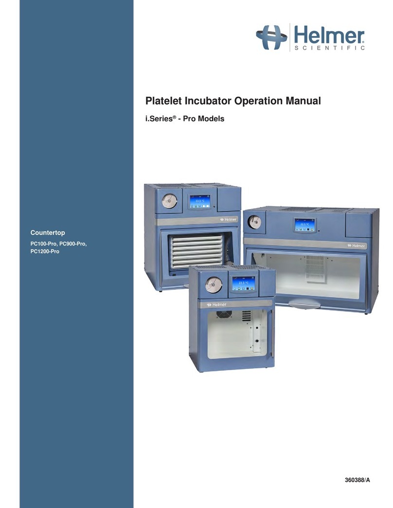
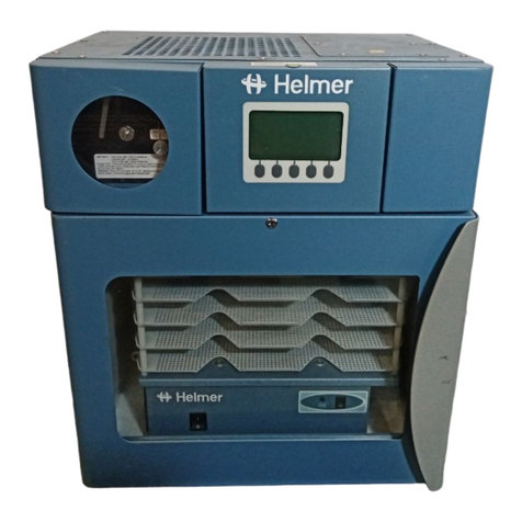
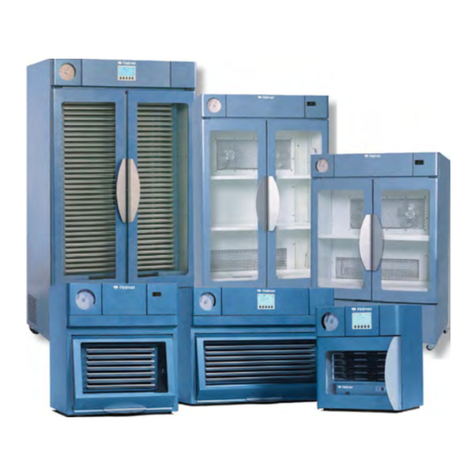
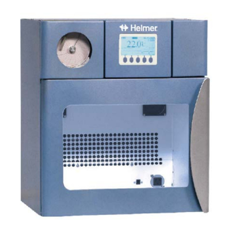
Helmer PC100i User manual

360093-1/H
i.Series™
Countertop: PC100i, PC900i, PC1200i Version A
Floor: PC2200i, PC3200i, PC4200i Version A
Horizon Series™
Countertop: PC100h, PC900h, PC1200h Version A
Floor: PC2200h, PC3200h, PC4200h Version A
Model
S/N
HELMER, INC. 14395 BERGEN BLVD., NOBLESVILLE, IN 46060 USA
PHONE (317) 773-9073 FAX (317) 773-9082
USA and CANADA (800) 743-5637
www.helmerinc.com
Platelet Incubator Operation Manual

i
360093-1/H
About this manual ..........................................................iv
1 Workingsafely...........................................................1
1.1 Understandingsafety-relatedlabels ...................................................1
1.2 Generalsafety....................................................................1
1.3 Electricalsafety...................................................................2
1.4 Chemicalandbiologicalsafety .......................................................2
2 Touringtheincubator .....................................................3
2.1 Touringthefrontandrightside .......................................................3
2.1.1 Touringthecontroldoorarea...............................................4
2.2 Touringthechamber ...............................................................5
2.3 Touringtherear...................................................................6
2.3.1 Touring the alarm output area...............................................7
2.4 Touring the top ....................................................................8
3 Installingtheincubator....................................................9
3.1 Reviewinginstallationandcongurationtasks ...........................................9
3.2 Recordingidenticationinformation...................................................11
3.3 Selecting an appropriate location.....................................................11
3.4 Movingtheincubator..............................................................12
3.5 Poweringtheincubator ............................................................12
3.5.1 Connecting to AC power..................................................12
3.5.2 TurningACpoweronandoff ..............................................12
3.6 Enablingbackuppower ............................................................13
3.6.1 Enablingbackuppowerforthei.Centermonitoringsystem .......................13
3.6.2 Enablingbackuppowerforthepowerfailurealarmsystem .......................14
3.6.3 Enablingbackuppowerforthemotionalarmsystem............................14
3.7 Installingthetubeforalarmchecks ...................................................15
3.8 Conguringtheincubatorsetpoint ....................................................15
3.9 Preparingthechartrecorder ........................................................16
3.10 Settingupagitatorsintheincubator ..................................................16
3.10.1 Understanding model compatibility for Helmer agitators and incubators .............16
3.10.2 Setting up a Helmer agitator inside an incubator . . . . . . . . . . . . . . . . . . . . . . . . . . . . . . . 17
3.11 Connectingexternalmonitoringdevices ...............................................19
3.11.1 Connecting to the remote alarm interface . . . . . . . . . . . . . . . . . . . . . . . . . . . . . . . . . . . .19
4 Preparing the monitoring system on i.Series incubators . . . . . . . . . . . . . . . . . . . . . . .20
4.1 Touring the i.Center monitoring system ................................................20
4.1.1 TouringtheHOMEscreen ................................................20
4.1.2 TouringtheMAINscreen .................................................21
4.2 Viewing current settings............................................................23
4.3 Changing unit and format settings ....................................................24
4.3.1 Changingthedisplaylanguage ............................................24
4.3.2 Changing date and time information.........................................24
4.3.3 Changing the temperature units ............................................25
Contents
Contents

ii
360093-1/H
4.4 Changingalarmsettings ...........................................................26
4.4.1 Changing the setpoints for temperature alarms ................................26
4.4.2 Changing the setpoints for the door open and power failure alarms ....................26
4.4.3 Changing the settings for motion alarms . . . . . . . . . . . . . . . . . . . . . . . . . . . . . . . . . . . . .27
4.4.4 Changing the audible alarm characteristics . . . . . . . . . . . . . . . . . . . . . . . . . . . . . . . . . . . 29
4.4.5 Changing the setting for the chart paper timer .................................30
4.5 Enabling and disabling the temperature graph . . . . . . . . . . . . . . . . . . . . . . . . . . . . . . . . . . . . . . . . . .30
4.6 Changing the password ............................................................31
4.7 Restoringfactorydefaults ..........................................................32
5 Preparing the alarm system on Horizon Series incubators ....................... 33
5.1 Viewing and changing the setpoints for temperature alarms ................................33
5.2 Delaying when alarms are communicated ..............................................34
5.2.1 Delaying temperature alarms ..............................................34
5.2.2 Delayingthemotionalarm................................................35
5.3 Changing the volume for audible alarms ...............................................36
5.3.1 Changing the volume for the temperature and power failure alarms ....................36
5.3.2 Changing the volume for the motion alarm....................................37
6 Using the incubator ......................................................38
6.1 Understanding how opening the door affects operation. . . . . . . . . . . . . . . . . . . . . . . . . . . . . . . . . . . .38
6.2 Understanding visual alarms and messages ............................................39
6.2.1 Determining when the chamber heater is running . . . . . . . . . . . . . . . . . . . . . . . . . . . . . . 39
6.2.2 Identifying active alarms on Horizon Series models.............................39
6.2.3 Identifying active alarms on i.Series models . . . . . . . . . . . . . . . . . . . . . . . . . . . . . . . . . .39
6.2.4 Understanding when the HOME screen appears ...............................40
6.2.5 Understanding the temperature graph and when it appears . . . . . . . . . . . . . . . . . . . . . .40
6.2.6 Understanding the agitator maintenance reminder and when it appears .............41
6.3 Changingthechartpaper ..........................................................41
6.4 Controlling the sound for audible alarms ...............................................41
6.4.1 Muting audible alarms on i.Series models . . . . . . . . . . . . . . . . . . . . . . . . . . . . . . . . . . . . 41
6.4.2 Muting audible alarms on Horizon Series models . . . . . . . . . . . . . . . . . . . . . . . . . . . . . .42
6.4.3 Enabling and disabling audible alarms on Horizon Series models..................42
6.5 Adjusting the screen contrast........................................................43
6.6 Rolling out shelves................................................................43
6.7 Storingitemsinthebuilt-inagitator...................................................43
6.7.1 Loading platelet bags in the built-in agitator ...................................44
6.7.2 Identifying the contents of the agitator drawers . . . . . . . . . . . . . . . . . . . . . . . . . . . . . . . . 44
6.8 Lockingthedoors.................................................................45
6.9 Viewing real-time information........................................................45
6.9.1 Viewing real-time agitation information.......................................45
6.9.2 Viewing the chart paper status .............................................46
6.9.3 Viewingthedoorstatus ..................................................46
6.9.4 Viewing the condenser temperature.........................................46
6.10 Viewing historical information........................................................46
6.10.1 Viewingtheeventlog....................................................47
6.10.2 Viewing the agitator count log. . . . . . . . . . . . . . . . . . . . . . . . . . . . . . . . . . . . . . . . . . . . . .48
6.11 Gettinghelp.....................................................................49
Platelet Incubator Operation Manual

iii
360093-1/H
7 Maintaining the incubator .................................................50
7.1 Reviewing the preventive maintenance schedule . . . . . . . . . . . . . . . . . . . . . . . . . . . . . . . . . . . . . . . .50
7.2 Testingandreplacingbatteries ......................................................52
7.2.1 Checkingandreplacingbatteriesforthei.Centermonitoringsystem ...............52
7.2.2 Testing and replacing the battery for the power failure alarm......................52
7.2.3 Replacing the battery for the motion alarm....................................53
7.3 Cleaning the incubator .............................................................54
7.3.1 Cleaning the condenser grill ...............................................54
7.3.2 Cleaningtheexterior ....................................................54
7.3.3 Cleaning the interior .....................................................54
7.3.4 Cleaningdoorgaskets ...................................................54
7.4 Maintaining moving parts on the built-in agitator .........................................54
7.4.1 Maintaining drawers .....................................................55
7.4.2 Maintaining the drive shaft and motor . . . . . . . . . . . . . . . . . . . . . . . . . . . . . . . . . . . . . . .56
7.4.3 Maintaining the wheels ...................................................56
7.5 Replacing an agitator ..............................................................57
7.5.1 Resetting agitator cycle counters on i.Series models............................57
7.6 Calibrating the temperature controller readout . . . . . . . . . . . . . . . . . . . . . . . . . . . . . . . . . . . . . . . . . .58
7.7 Calibrating temperature readings on the i.Center . . . . . . . . . . . . . . . . . . . . . . . . . . . . . . . . . . . . . . . .59
7.8 Testingchambertemperaturealarms .................................................60
7.8.1 Testing temperature alarms on Horizon Series models . . . . . . . . . . . . . . . . . . . . . . . . . . 61
7.8.2 Testing temperature alarms manually on i.Series models . . . . . . . . . . . . . . . . . . . . . . . .63
7.8.3 Testing temperature alarms automatically on i.Series models .....................66
7.9 Testingthepowerfailurealarm ......................................................67
7.10 Testingthemotionalarm...........................................................68
7.11 Testingthedooropenalarm ........................................................68
7.12 TestingtheNoBatteryalarm........................................................69
8 Understanding and addressing operational issues . . . . . . . . . . . . . . . . . . . . . . . . . . . .70
8.1 Addressinggeneraloperationproblems ...............................................70
8.2 Addressing chamber temperature problems . . . . . . . . . . . . . . . . . . . . . . . . . . . . . . . . . . . . . . . . . . . .71
8.3 Addressing alarm activation problems .................................................72
8.4 Addressingtestingproblems........................................................76
8.5 Addressing condensation problems...................................................76
8.6 Resettingthei.Centermonitoringsystem ..............................................77
8.7 Viewing manufacturer and product information . . . . . . . . . . . . . . . . . . . . . . . . . . . . . . . . . . . . . . . . . .77
9 Reference information....................................................78
9.1 i.Center monitoring system screen reference . . . . . . . . . . . . . . . . . . . . . . . . . . . . . . . . . . . . . . . . . . .78
9.2 Alarm reference ..................................................................80
9.3 Technicalspecications ............................................................80
9.3.1 Power ................................................................80
9.3.2 Weight. . . . . . . . . . . . . . . . . . . . . . . . . . . . . . . . . . . . . . . . . . . . . . . . . . . . . . . . . . . . . . . .82
9.3.3 Size..................................................................82
9.3.4 Operating conditions.....................................................82
9.3.5 Agitation speed.........................................................82
9.3.6 Energy conservation and regulatory compliance . . . . . . . . . . . . . . . . . . . . . . . . . . . . . . . 83
9.3.7 Supplies..............................................................83
Rel.i™ProductWarranty ....................................................84
Contents

iv
360093-1/H
Platelet Incubator Operation Manual
About this manual
Welcome to the Platelet Incubator Operation Manual. This section explains the symbols and conventions used in this manual,
copyright information about this document, and trademark information for products supplied by Helmer.
Symbols and conventions
Several symbols and conventions are used in this manual.
Warnings
A Warning is used to call attention to a condition or possible situation that could cause injury to the operator.
!
WARNING:
Cautions
A Caution is used to call attention to a condition or possible situation that could damage or destroy the equipment or the
!
CAUTION:
obstructions before starting agitation.
Notes
topic, or background information about a design characteristic.
NOTE:
purchase through Helmer.
Model references
Generic references are used throughout this manual to group models that contain similar features. For example, “PC100”
as such.
Copyright and trademark information
Copyright © 2008 Helmer, Inc.
AgiTrak™, Horizon Series™, i.Help™, and Rel.i™ are trademarks of Helmer, Inc.
i.Center™ and i.Series™ are registered trademarks of Helmer, Inc. in the United States of America.

1
360093-1/H
Working safely
1 Working safely
This section describes general safety information for installing, using, and maintaining the incubator. Your
organization may provide additional safety information.
1.1 Understanding safety-related labels
Warning Caution, hot surface
CAUTION: Do not open more than
one drawer at a time.
Protective earth ground terminal CAUTION: Do not open more than one drawer at a time
1.2 General safety
►
► Do not use the incubator if its components are damaged. Notify the appropriate personnel in your
organization for guidance regarding usage and maintenance.
► Never attempt to physically restrict any of the moving components.
► Do not move or bump the incubator during operation.
►
►
manual should only be performed by technical service representatives authorized by Helmer.
► When lifting a countertop incubator, hold it on the ends of the base and lift. If the incubator is too
►
operation instructions for them.

2
360093-1/H
Platelet Incubator Operation Manual
1.3 Electrical safety
!
WARNING:
instructions.
► Inspect all electrical equipment and address any problems prior to installation.
► Avoid removing covers from the incubator unless instructed to do so.
►
►
1.4 Chemical and biological safety
!
WARNING:
organization.
►
►
► Appropriate handling and disposal of materials that are infectious, toxic, pathological, radioactive, or
►
environmentally harmful.
!
WARNING:
decontaminate them as appropriate. Any items that have not been
the contents are not contaminated and are safe to handle must accompany all
returns. Contact Helmer or your distributor for decontamination instructions and
a return authorization number.

3
360093-1/H
Touring the incubator
2 Touring the incubator
Congratulations on your purchase of a Helmer Platelet Incubator. The incubator provides precise
temperature control and monitoring for your platelet storage needs.
model or options selected at the time of purchase. The location of components also varies by model.
2.1 Touring the front and right side
D
E
A
B
C
HF
G
Left:Sampleoormodel(PC4200imodelshown).Middletop:Samplecountertopmodel(PC100h
modelshown).Middlebottom:Rightsideofoormodels.Right:Samplemodelwithhood-style
door(PC900imodelshown).
Label Description Function
A Chart recorder
appear on your incubator)
Records seven days of chamber temperature
information
i.Center monitoring system
(Applies to i.Series models only)
Displays current status information and provides an
interface to change alarm setpoints
C
(Applies to PC4200 models only)
Holds and organizes items being agitated
D Control door area Contains controls for the incubator. For details, see
Section 2.1.1, “Touring the control door area.”
E Door lock Prevents unauthorized access to the chamber
F
Contains parts used to change the temperature of
the chamber. On PC4200 models, it also contains
parts to agitate the storage frame
G Casters
Used to move the incubator and lock it into
position
H Condenser grill
Air intake for the compressor

4
360093-1/H
Platelet Incubator Operation Manual
2.1.1 Touring the control door area
E
C
B
A
F
D
Left:Controlsfori.Seriesmodels(PC2200imodelshown).Center:KeyswitchforPC4200h
models.Right:ControlsforHorizonSeriesmodel(PC100hmodelshown).
Label Description Function
A Control door
For Horizon models, the temperature controller is
For i.Series models, the temperature controller is
hidden.
models, it also starts and stops agitation.
C Temperature controller Controls the temperature of the chamber.
For Horizon Series models, it also displays current
status information and provides an interface to
change alarm setpoints.
D Varies by model.
►
►
temperature alarm and the motion alarm.
►
disables the temperature alarm.
E Mute button
(Horizon Series models only)
Temporarily mutes the audible alarm for high or
F
(Horizon Series models only)

5
360093-1/H
Touring the incubator
2.2 Touring the chamber
A
B
C
D
E
F
G
C
A
E
F
B
D
E
B
A
C D
H I F E
A
Left top: PC100i 115 V model. Right top: PC900i 230 V model. Left bottom: PC3200h 115 V
model.Rightbottom:PC4200imodel(withagitationsystemremovedtoshowdetail).
Label Description Function
A
the interior outlets.
Chamber fan Circulates air in the chamber
C Interior outlet
incubator
D I/O (input/output) connector
Agitators for motion information and alarms
E Temperature control and chart
recorder probe
Collects temperature data from the top of the
chamber for temperature control. This probe is
also used for chamber temperature monitoring on
Horizon Series models, and to collect temperature
data for the chart recorder (if installed).
F Temperature monitoring probe
(Applies to i.Series models only)
Collects temperature data from the chamber for
monitoring
G Tube for alarm checks
(Applies to PC100 models only)
Holds liquid that is used during probe tests
H
(Applies to PC2200 and PC3200
models only)
Supports equipment that is installed inside
the incubator, such as Helmer Flatbed Platelet
Agitators
I
(Applies to PC3200i and
PC4200i models only)
Collects temperature data from the bottom of the
chamber for monitoring

6
360093-1/H
Platelet Incubator Operation Manual
2.3 Touring the rear
A
B
CD
F
E
A
G
C
B
H
I
Left:Samplecountertopmodel(PC1200h230Vmodelshown).Topright:Sampleoormodel
(PC3200h115Vmodelshown).Bottomright:Detailofpowerconnectorfor230Voormodels.
Label Description Function
A Alarm output area Contains the alarm buzzer and remote alarm
interface. Other features vary by model. For details,
see Section 2.3.1, “Touring the alarm output area.”
Provides the model number, serial number, and
electrical requirements for the incubator
C
D Condenser grill
(Applies to countertop models
only)
Air intake for the compressor. The condensing unit
is located behind the grill.
E Water evaporation tray
(Applies to countertop models
only)
Contains condensate from the condensing unit
F Condensate evaporator
(Applies to countertop models
only)
G Circuit breakers
115 V)
Prevents current overload
H
230 V)
I Fuses
230 V)
Prevents current overload

7
360093-1/H
Touring the incubator
2.3.1 Touring the alarm output area
C DA
B
A
C D
G
D
F
E
DH E
J
KI
L
Left:Samplecountertopmodels(PC1200i230VandPC100h115Vshown).
Right:Sampleoormodels(PC4200handPC2200ishown,withdetailforPC4200hmodels).
Label Description Function
A Alarm buzzer
(Applies to i.Series models only)
Audibly indicates an active temperature, no battery,
an agitator that is installed in the incubator has stopped.
Circuit breakers
(Applies to countertop models
that are 230 V)
Prevents current overload
C Flash port
(Applies to i.Series models only)
D Remote alarm interface Provides a dry contact connection to external
central alarm systems
E Alarm buzzer
(Applies to Horizon Series
models only)
Audibly indicates an active temperature alarm or
F Circuit breaker
(Applies to countertop models
that are 115 V)
Prevents current overload
G
(Applies to all countertop models)
H Motion alarm buzzer
(Applies to PC4200h models only)
stopped
I I/O connector
(Applies to PC4200 models only)
Not used
J Alarm volume control
(Applies to PC4200 models only)
audible motion alarm
K Alarm delay control
(Applies to PC4200 models only)
Delays the communication of the motion alarm
L RS232 COM port
(Optional feature for i.Series
models only)

8
360093-1/H
Platelet Incubator Operation Manual
2.4 Touring the top
A B
Topview(PC100modelshown)
Label Description Function
A Service cover Covers components on top of the incubator
Access panel Provides access to components used for
Applicable components vary by model.

9
360093-1/H
Installing the incubator
3 Installing the incubator
3.1 Reviewinginstallationandcongurationtasks
NOTE: Regulations for your organization may require that only designated service
guidelines for your organization.
may vary depending on the model. For more information about each step, see the referenced sections.
Toinstallandconguretheincubator
1
2
see
3 Select an appropriate location for the incubator, then move the incubator into place. For more
information and precautions, see Section 3.3, “Selecting an appropriate location” and Section 3.4,
“Moving the incubator.”
4
so. For more information, see
5
see
6
information, see
7
system. For instructions, see
8
instructions, see
9 For PC100 models, install the tube for alarm checks. For more information, see Section 3.7, “Installing
the tube for alarm checks.”
10
temperature for your application. For more information and instructions to change it, see Section 3.8,
11
For details about your chart recorder, refer to the Chart
Recorder Operation Manual for your incubator.
12 For models other than PC4200 models, set up your agitator or agitators in the incubator. For more
information and instructions, see Section 3.10, “Setting up agitators in the incubator.”
13
more information and instructions, see Section 3.11, “Connecting external monitoring devices.”

10
360093-1/H
Platelet Incubator Operation Manual
14
formats. Change the formats as needed. For instructions, see
and Section 4.3, “Changing unit and format settings.”
15
needed. For i.Series models, see and Section 4.4.1, “Changing
the setpoints for temperature alarms.” For Horizon Series models, see
changing the setpoints for temperature alarms.”
16 For Horizon Series models, enable audible alarms. For more information, see Section 6.4.3, Enabling
and disabling audible alarms on Horizon Series models.”
17
delay period and motion alarm volume are set to the appropriate values. Change them as needed. For
more information and instructions, see and
Section 5.3, “Changing the volume for audible alarms.”
18
and condenser temperature setpoint. Change the values as needed. For instructions, see Section 4.2,
and Section 4.4, “Changing alarm settings.”
19
as needed. For instructions, see and Section 4.4.3, “Changing
the settings for motion alarms.”
20
needed. For instructions, see and Section 4.4.4, “Changing the
audible alarm characteristics.”
21
the values as needed. For instructions, see Section 4.4.5,
“Changing the setting for the chart paper timer,” and Section 4.5, “Enabling and disabling the
temperature graph.”
22
For instructions, see
23 Calibrate the temperature controller so that the readout for the chamber temperature matches the
temperature of the chamber. For more information and instructions, see Section 7.6, “Calibrating the
temperature controller readout.”
24 For i.Series models, calibrate the i.Center so that readout for the temperature monitoring probe matches
Section 7.7, “Calibrating temperature readings on the i.Center.”
25 Section 7.8, “Testing
chamber temperature alarms” through
26

11
360093-1/H
Installing the incubator
3.2 Recordingidenticationinformation
REF
Serial Number
Weight 663 lb / 301 kg
Voltage 115V
PC4200i
000000
Version A
Platelet Storage System
Noblesville, IN USA www.helmerinc.com
2007
Hz 50/60
Amps 14.5 A
REF
Serial Number
PC4200i
000000
Version A
www.helmerinc.com
A
B
C
D
E
F
Sampleproductidenticationlabels.Left:Labelinchamber.Right:Labelonrear.
Label Description
A Model
Serial number (S/N)
C WEEE symbol. For more information, see
regulatory compliance.”
D
E Date of manufacturing
F CE symbol. For more information, see
regulatory compliance.”
3.3 Selecting an appropriate location
►
and the chamber to drain properly
► Is clear of direct sunlight, high temperature sources, heating vents, and air conditioning vents
►
unobstructed ventilation
►
for unobstructed ventilation
►
►
information, see

12
360093-1/H
Platelet Incubator Operation Manual
3.4 Moving the incubator
!
WARNING: ►
assistance as needed.
►
evaporation tray, located on the rear of the incubator, as a handle. Avoid
►
unlocked and that the doors are closed. When moving the incubator, push
from the sides of the incubator, not from the front or back. Pushing from the
3.5 Powering the incubator
3.5.1 Connecting to AC power
installed inside the incubator.
To connect to AC power
!
CAUTION:
incubator is at room temperature.
1
connector on the incubator.
2
3.5.2 Turning AC power on and off
NOTE:
operating temperature is reached, the alarm clears automatically. For information
and instructions to mute or disable the alarm, see Section 6.4, “Controlling the
sound for audible alarms.”
appropriate languages prior to shipment. For more information about available languages and instructions
your local distributor.

13
360093-1/H
Installing the incubator
To turn the power on (i.Series models)
1
2
displayed in the most recently selected language. The Language setting is highlighted, and the language
battery for the motion alarm starts charging.
3
4
5 Press the HOME button. The HOME screen appears. Display text for all screens changes to the
language you selected.
To turn the power on (Horizon Series models)
1
2
The current temperature of the chamber appears on the temperature controller. For PC4200h models, the
3
backup battery.
To turn the power off
► ) position.
3.6 Enabling backup power
the incubator is lost.
For information about the backup battery for the chart recorder, see
3.6.1 Enabling backup power for the i.Center monitoring system
NOTE: This section only applies to i.Series models.
incubator and activate all alarms as appropriate.
The batteries are located under the access panel on top of the incubator. For more information about replacing
batteries, see Section 7.2.1, “Checking and replacing batteries for the i.Center monitoring system.”

14
360093-1/H
Platelet Incubator Operation Manual
To enable backup power for the i.Center monitoring system
!
WARNING: Removing the access panel from the incubator exposes you to the risk of electric
shock. Regulations for your organization may require that only designated service
1
2
batteries installed. The batteries are located on top of the incubator under the access panel.
3 │) position. The key is shipped from the factory in
3.6.2 Enabling backup power for the power failure alarm system
NOTE: This section only applies to Horizon Series models.
incubator is lost.
The battery is located behind the control door on the front of the incubator. Depending on the model, you may
need to connect the leads to the battery. For more information about replacing the battery, see Section 7.2.2,
To enable backup power for the power failure alarm system
►
3.6.3 Enabling backup power for the motion alarm system
NOTE:
Unlike other backup batteries for the incubator, the battery for the motion alarm system is rechargeable.
the battery, see Section 7.2.3, “Testing and replacing the battery for the motion alarm.”
To enable backup power for the motion alarm system (PC4200 models only)
!
WARNING: Removing the access panel from the incubator exposes you to the risk of electric
shock. Regulations for your organization may require that only designated service
1
2
3

15
360093-1/H
Installing the incubator
3.7 Installing the tube for alarm checks
NOTE: This section applies only to PC100 models.
The accessories box for PC100 models includes a tube that is used for alarm checks. This tube must be
!
CAUTION: Leaving the probe covered during operation prevents the probe from accurately
reading the chamber temperature.
Tube installed. Left: PC100i model. Right: PC100h model.
3.8 Conguringtheincubatorsetpoint
The incubator setpoint is used by the temperature controller to adjust the chamber temperature of the
and turned on. The temperature controller senses the temperature in the chamber through the temperature
activates the chamber heater until the chamber temperature returns to the setpoint.
At the factory, the incubator setpoint is set at 22.0 °C. You may need to change the setpoint if your
organization requires a different normal chamber temperature.
NOTE: Depending on purchasing requirements for your organization, the default
for your incubator and note any differences for future reference.
Toconguretheincubatorsetpoint
!
CAUTION: Do not change the refrigerator setpoint to a value outside the temperature control
range. For more information, see
1
normal temperature to be 22.0 °C, but it may be different for your organization.
2 On the front of the incubator, open the control door to access the temperature controller. The current
temperature of the chamber appears on the display. The current temperature may be different from the
setpoint, especially if the chamber temperature has not yet stabilized.
Other manuals for PC100i
1
This manual suits for next models
11
Table of contents
Other Helmer Accessories manuals
Popular Accessories manuals by other brands

SICK
SICK SIM1012 operating instructions

Crearoma
Crearoma Airing6-S product manual

Honeywell Home
Honeywell Home RDWL515A2000 Installation and operation guide
Dometic
Dometic TropiCool TC14 operating manual
Hytronik
Hytronik HN020-01V instruction manual

Microchip Technology
Microchip Technology MCP355X user guide

Burster
Burster 86-2112 Operation manual
ANALOX
ANALOX COSAMS Generic user manual

Industrial Data Systems
Industrial Data Systems IDS 410 Installation, calibration and operations manual

COMPX
COMPX Stock Locks C2018 Dimensional drawing

Siemens
Siemens SITRANS WS100 instruction manual
Axxess
Axxess Relay & Contact Sensor-6 installation guide
