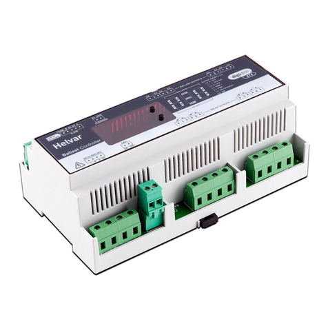
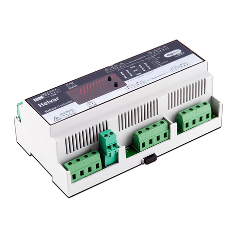
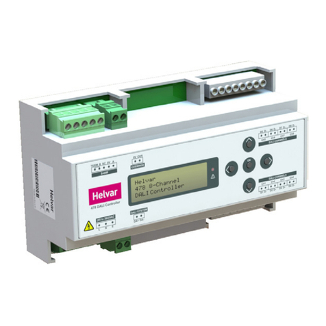
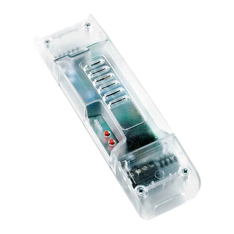
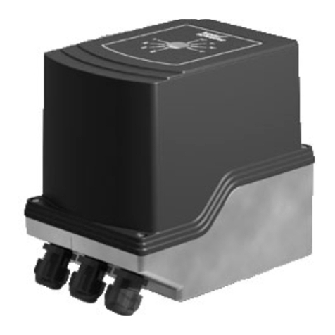
HELVAR INTELLIGENT LCM-478 User manual

HelvarLCM‐478InstallationGuide Helvardoc.no.7860397,issue01
Page1of14
HELVAR INTELLIGENT LCM-478
INSTALLATION GUIDE

HelvarLCM‐478InstallationGuide Helvardoc.no.7860397,issue01
Page2of14
CHECKTHESYSTEMDIAGRAM.....................................................................................................................3
EXAMPLESYSTEMDIAGRAM........................................................................................................................4
FIXTHELCMINTOCEILINGORTOAWALL....................................................................................................5
CONNECT‘POWERIN’(MAINSPOWER)........................................................................................................6
CONNECTDALILUMINAIRES(PORTS1TO10)...............................................................................................7
CONNECTINPUTDEVICES(E.G.SENSORSANDBUTTONPANELS)..................................................................8
CONNECTDALIINANDDALIOUT.................................................................................................................9
CONNECTORSFORTHELCM‐478,WITHWIRINGDETAILS............................................................................11
CONNECTORSFORPORTS1TO10:DALILUMINAIRESANDDALIDEVICES........................................................................11
CONNECTORSFORPORTSDALIINANDDALIOUT.....................................................................................................12
CONNECTORFORPORT‘POWERIN’........................................................................................................................13
CONNECTORSFORPORTSS1ANDS2........................................................................................................................14
For more information: www.helvar.com/lcm , or use this QR code

HelvarLCM‐478InstallationGuide Helvardoc.no.7860397,issue01
Page3of14
CHECK THE SYSTEM DIAGRAM
Install the LCMs according to the system diagram.
The system diagram refers to the LCM serial numbers. The serial number is on the label on
each LCM-478.

HelvarLCM‐478InstallationGuide Helvardoc.no.7860397,issue01
Page4of14
EXAMPLE SYSTEM DIAGRAM
This is an example of a system with five LCM-478s.

HelvarLCM‐478InstallationGuide Helvardoc.no.7860397,issue01
Page5of14
FIX THE LCM INTO CEILING OR TO A WALL
Mounting the Intelligent LCM can be installed on the ceiling or wall-mounted.
Attach the Intelligent LCM to a flat, smooth surface.
The installation must meet all relevant building regulations.
The device wiring must comply with the requirements of the most recent IEE wiring
regulations (see BS7671).
Recommended mounting screws:
No. 8 (ø 4 mm) or No. 10 (ø 5 mm) screws with head diameter of 6 mm to 9 mm
Access and clearance
The installed Intelligent LCM and all connectors must be easy to access. Allow 300 mm
clearance (clearance = total height of the Intelligent LCM and connectors and cables).
Important: install clear of obstructions
Attach the Intelligent LCM downwards and clear of obstructions, such as ventilation shafts
and wiring ducts. The Intelligent LCM and connectors should be visible and accessible to
ensure easy connection and maintenance.

HelvarLCM‐478InstallationGuide Helvardoc.no.7860397,issue01
Page6of14
CONNECT ‘POWER IN’ (MAINS POWER)
Connect mains power to the LCM-478. The LCD display will power on and show some text.

HelvarLCM‐478InstallationGuide Helvardoc.no.7860397,issue01
Page7of14
CONNECT DALI LUMINAIRES (PORTS 1 TO 10)
Connect the DALI luminaires to ports 1 to 8 and 9 and 10.
Label the connectors with the stickers provided: if a connector is removed this makes it
simple to reconnect it to the correct port.

HelvarLCM‐478InstallationGuide Helvardoc.no.7860397,issue01
Page8of14
CONNECT INPUT DEVICES (e.g. SENSORS and BUTTON
PANELS)
Connect the input devices (e.g. Helvar Sensor 321, or Helvar button panel 135) to ports S1
and S2.

HelvarLCM‐478InstallationGuide Helvardoc.no.7860397,issue01
Page9of14
CONNECT DALI IN and DALI OUT
Connect the DALI line according to the system diagram.
Connect the DALI cable from the DALI subnet terminal of Helvar lighting router to
‘DALI IN’ on the first LCM-478 in the DALI subnet.
Connect DALI OUT of the first LCM-478 to DALI IN of the next LCM-478 in the DALI
subnet, and so on. No ‘DALI OUT’ connection is required from the last LCM-478 in a
DALI subnet.
Note: DALI is open topology , so a star or redial configuration can be used if required .
The maximum devices per subnet should not exceed the 64 devices or 250 mA.
Refer to individual device datasheets or contact Helvar technical support for advice
DALIIN
DALIOUT

HelvarLCM‐478InstallationGuide Helvardoc.no.7860397,issue01
Page10of14
DALI TEST (for output ports 1 to 8)
‐With mains power connected to the LCM-478, and the DALI luminaires connected, test
the system by dimming the lights down then up again.
To do this
1. Press and hold the ‘Down’ button. The DALI luminaires should dim down.
2. Press and hold the ‘Up’ button. The DALI luminaires should dim up.
To test the luminaires for ports 9 and 10, plug these luminaires into any of the ports 1 to 8
and confirm dimming operation as above.
UP
DOWN

HelvarLCM‐478InstallationGuide Helvardoc.no.7860397,issue01
Page11of14
CONNECTORS FOR THE LCM-478, with wiring details
ThissectionshowswhichconnectorsarerecommendedforconnectiontotheLCM‐478,andwiring
detailsforthoseconnectors.
TheWielandpartnumbersgivenincludecolourcodes.Consultyourconnectorsupplierfor
alternativestotheserecommendations.
Connectors for ports 1 to 10: DALI luminaires and DALI devices
Wieland male connector GST18i5 S1 ZR1 S PB02, 5 pole, male, flat version, screw
connection, 250/400 V, 20 A, colour of coding: pastel blue, colour of housing: black
Wieland part number: 92.954.4453.0

HelvarLCM‐478InstallationGuide Helvardoc.no.7860397,issue01
Page12of14
Connectors for ports DALI IN and DALI OUT
Wieland male connector with strain relief GST18I3S S1 ZR1 TB06, 3-pole, male, screw
connection, 250 V, 20 A, colour of coding: turquoise blue, colour of housing: black
Wieland part number: 92.932.4053.0

HelvarLCM‐478InstallationGuide Helvardoc.no.7860397,issue01
Page13of14
Connector for port ‘POWER IN’
Wieland female connector with strain relief GST18I3S B1 ZR1 SW, 3-pole, female with screw
connection, coding mains 250 V, 20 A, coding colour black, strain relief color black
Wieland part number: 92.931.3053.1

HelvarLCM‐478InstallationGuide Helvardoc.no.7860397,issue01
Page14of14
Connectors for ports S1 and S2
Wieland male connector with strain relief GST15I2S S1 ZR1WW PB01, 2-pole, male, screw
connection, 250V/6A, color of coding: pastel blue, color of housing: white
Wieland part number: 91.922.3453.0
Table of contents
Other HELVAR Controllers manuals
