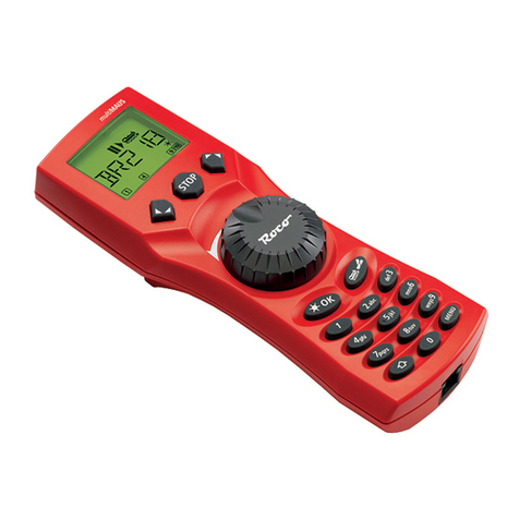
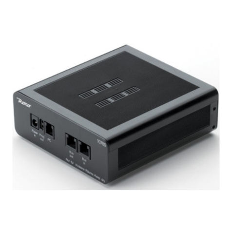
roco MultiMAUS User manual

31
TABLE OF CONTENT
The evolution of the ROCO Lokmaus – the
multi
MAUS ................................................................... 32
An overview of the
multi
MAUS ....................................................................................................... 32
Section 1 • Basics – Get to know the
multi
MAUS
Connecting the
multi
MAUS ............................................................................................................. 33
The display screen ............................................................................................................................ 34
The keys ........................................................................................................................................... 34
Operating the
multi
MAUS
1. Start .......................................................................................................................................... 36
2. Type of locomotive access ........................................................................................................ 36
3. Driving and functions ............................................................................................................... 39
4. The emergency stop functions .................................................................................................. 40
5. Turnout control ....................................................................................................................... 40
6. Quick-programming ................................................................................................................. 42
7. Short circuit and overload ........................................................................................................ 43
Section 2 • The Menus – Programming for advanced users
The menu functions of the
multi
MAUS ............................................................................................ 44
Overview of the menu structure ....................................................................................................... 45
1. The “Loco” menu ..................................................................................................................... 47
2. The “Programming” menu ....................................................................................................... 49
3. The “Settings” menu ................................................................................................................ 50
Section 3 • Appendix – Useful information about the
multi
MAUS
and the subject of digital technology
Compatibility of the
multi
MAUS – all useable devices .................................................................... 53
Using Locomotives without a decoder and the
multi
MAUS ............................................................. 53
The master-and-slave principle ......................................................................................................... 54
Combination of digital and non-digital system parts ....................................................................... 54
The 10765 booster ........................................................................................................................... 55
Terminal loops in digital operation .................................................................................................. 56
Glossary ........................................................................................................................................... 56
Hints, Tips & Help ............................................................................................................................. 57
Programming help for Lokmaus 2 / R3 –
multi
MAUS ....................................................................... 58
Error messages ................................................................................................................................. 59
Fig. 1 – 5: Connection options .......................................................................................................... 60 – 64

32
THE EVOLUTION OF THE ROCO LOKMAUS — THE
multi
MAUS
The
multi
MAUS brings together the functionality of the legendary Lokmaus with the comfort of a fully
digital central control unit. Whether you use the
multi
MAUS as just a comfortable controller or wish to use
it for comprehensive programming of your locomotive decoder and turnouts, the clear layout of the design
and simple operation make the
multi
MAUS the leading digital model railroading controller.
Our aim when developing this Lokmaus was to make operation as intuitive as possible. The addition of
the various new functions can be easily controlled. This manual is designed to introduce you to all the
capabilities of the
multi
MAUS.
In order to make this manual clear and easy to understand, it is broken down into several sections.
Beginning users that wish to use the
multi
MAUS only for playing are not required to read the entire
manual. The first section is sufficient for simple, everyday use.
This first section of the manual deals with the basics for connecting and operating the multiMAUS. Users
who wish to use the many diverse programming options of the
multi
MAUS will find instructions in the
second section of this manual. The third section serves as a guide for special cases involving digital model
railroading. The glossary contains the definitions of basic terms that you may encounter while spending
time with your digital system.
Have fun reading this manual and, of course, using the
multi
MAUS.
Modelleisenbahn GmbH
AN OVERVIEW OF THE
multi
MAUS
The concept
Ergonomic shape for one-hand operation
Large LCD with backlight
Simple methods for setting speed and direction of travel of the locomotives using the rotary knob
Rotary knob with zero locking position
Multilingual operation
Compatibility with other DCC / NMRA-compatible controllers
The ROCO digital system is expandable to include up to 31 input devices such as extra Lokmaus or
multi
MAUS devices, RouteControl etc.
Future updates via RS485 and ROCOMOTION (X-Bus)
The features
Managing 9,999 locomotive addresses & Deciding between locomotive library or locomotive address
Alphanumerical locomotive name display with locomotive database for 64 entries, i.e. locomotives
Locomotive control with 14, 28 and 128 speed steps which can be set for each locomotive individually
Control of light and 20 additional functions for locomotives
Control up to 1,024 turnout addresses
Writing configuration variables (DCC-CVs)
Safety
Emergency stop with shut-down of the entire system
Emergency stop for the selected locomotive
Child lock for functions which may could be problematic for children (e.g. programming)

33
SECTION 1 • BASICS
CONNECTING THE
multi
MAUS
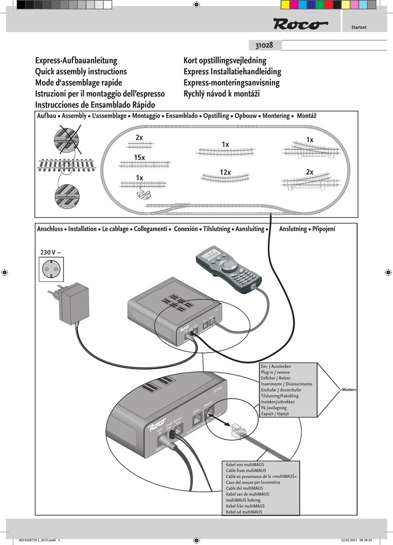
Fig. 2 on page 61 shows the basic connection. For a fully-functional ROCO digital system with the
multi
MAUS, you will need the following components:
– A 10764 amplifier,
– A 10725 transformer,
– And a 61190 feeder track. If you are using another feeder track or system, make sure that there is no
capacitor in the feeder track.
You will find information on other devices which you can use with the
multi
MAUS in the chapter “COMPAT-
IBILITY OF THE
multi
MAUS” in the third section of this manual.
Please pay attention to the following instructions before you start connecting components:
The warranty will be voided if you are using ROCO components together with components from other
companies. In addition there is a risk of damage or malfunction to your digital system. Your warranty
will also be void if you open the housing of the
multi
MAUS.
Please only carry out any connection work with the operating voltage switched off (as an exception:
connection of further X-Bus based equipment, see below). Work carefully and make sure to avoid short
circuits at all costs when connecting to the track system. An incorrect connection may destroy the digital
components. You should also seek the advice of a specialist or local dealer.
To operate the digital system without faults, you should avoid extending the connecting cable to the
master mouse.
It is imperative that you do not connect a normal transformer on the same circuit parallel to the digital
controller. This could destroy the digital booster!
1. Plug the feeder track cable into the track socket “Track Out” on the amplifier.
2. Plug the hollow plug, which is connected to the transformer by the two-pin cable, into the “Power
In” socket.
3. Connect the
multi
MAUS and the amplifier using the cable included with your system. Plug the cable
into the connection socket on the booster labeled “Master”.
4. You can now (and not beforehand) connect the transformer to the mains socket. This way you avoid
damaging the digital system.
The socket labeled “slave” is for connecting a further
multi
MAUS, a Lokmaus 2 / R3, the RouteControl
10772 or a PC with the ROCOMOTION software. In this case you should have switched the system on. This
ensures that the automatic allocation of the X-Bus addresses will be without any problems. If more than
one of these devices are to be connected, you will require the data BUS distributor 10758.
If you use a Lokmaus 2 / R3 as a master, you will be unable to use some of the functions performed by a
multi
MAUS set as a slave. We therefore recommend that you use a
multi
MAUS as the master. See also
the chapter “MASTER-AND-SLAVE PRINCIPLE” in the third section of this manual.
Note on the instructions
Text that contains an “” before a word refers to a definition in the “GLOSSARY” in section three.
“+” in the diagrams means that both the keys mentioned must be pressed together.
“/” in the diagrams stands for a selection of one of the two keys mentioned.

34
THE KEYS
The clear concept of the
multi
MAUS reduces the number of the keys to an expedient quantity. Functions
needed for ordinary playing can mostly be called by the particular keys. These keys will be shown here.
Please also note fig. 1 on page 60.
Note: The “arrow keys” – like all other keys – only have one single function despite having two arrows
printed on them.
When selecting key combinations using “Shift” – same as the “MENU” key – and another key, the “Shift”
key has to be pressed before any other key – like on a computer keyboard.
Arrow keys
– in combination with —
Shift key
– in combination with —
menu key
– Scroll through the locomotive library (library menu)
– Search for locomotive addresses (locomotive address mode)
– Set the turnout (straight or branch-off, turnout mode)
– Scroll through a menu level
In library mode:
– Freshly arrange order of locomotives by shifting
In locomotive address mode:
– Scroll 100 positions (search functions)
In turnout mode:
– Scroll through the turnout numbers (search function)
In locomotive address mode:
– Rearrange speed steps
Light symbol (light / OK key)
– locomotive light switched on
Turnout symbol
(locomotive / turnout key)
– the
multi
MAUS is in the turn-
out mode
Locomotive symbol
(locomotive / turnout key)
– drive mode
– with “MENU”: “LOCO” menu
Short circuit
– the symbol flashes in the event of
a short circuit or an overload
Stop (stop key)
– the symbol flashes in the
event of an emergency
stop or short circuit
MENU
– the
multi
MAUS is
in the menu level
Prog
– lights up as a confirmation
when programming
– the
multi
MAUS is in the “PRO-
GRAMMING” menu level
ABC
– lights up when text
is being entered
Wrench
– the
multi
MAUS is in the
“Settings” menu level
Function symbols (1 – 10)
– display the currently activated
special locomotive functions
– showing sub-item ranks in the
menu level
Drive symbols
– Arrows shows the direction of
travel of the selected locomotive
– “II” denotes that the locomotive
is at a standstill (by controller or
selected emergency stop)
Shift symbol
– is shown as confirma-
tion of the shift key
THE DISPLAY SCREEN
All the functions of the
multi
MAUS can be checked on the large LCD with backlight. The symbols are as
follows:

35
Light / OK key
– in combination with —
Shift key
– Switch the light on or off (in drive mode)
– Confirm inputs (in turnout mode and in the menus)
– Call up desired menu level or menu items
In locomotive address mode:
– Select another locomotive by directly inputting an locomotive address
Stop key
– in combination with —
Shift key
In drive mode:
– Emergency stop on entire system
In menu mode:
– Return from the respective menu level
In drive mode:
– Selective emergency stop for the locomotive selected and displayed
Locomotive / turnout key
– in combination with —
Shift key
– Switch between locomotive and turnout mode
– Switch between library and locomotive address mode
…
Function keys
– in combination with —
Shift key
In drive mode:
– Switch the locomotive functions F1 – F10 on or off directly. The locomotive
functions F11 – F20 are switched using keys 1 – 10 together with the shift
key. The activated locomotive functions can be seen on the display screen.
In menu mode:
– Input a locomotive name (alphanumerical) in the library
– Fast access to the menu items out of the menu level
In turnout mode:
– Input turnout number directly
– Switch locomotive functions F11 – F20 on or off. You can check the acti-
vated functions by pressing the “shift” key.
In turnout mode:
– Call up to 10 saved turnouts (turnout shortcut keys)
Shift key
In drive mode:
– Check the activated functions F11 – F20
menu key
– in combination with —
Shift key
– in combination with —
…
Function keys
– Switch to menu mode (press and hold for approximately 5 seconds)
– Return directly from all menu levels to locomotive / turnout mode
– Switch to menu mode
– Return directly from all menu levels to locomotive / turnout mode
In library or locomotive address mode:
– Quick-program CVs 1 – 5 and 8 (“MENU“ key must be pressed first)

36
OPERATING THE
multi
MAUS
Despite its numerous options, operation of the
multi
MAUS is simple and intuitive. A concept which had
already been successfully introduced for the Lokmaus models of the first and second generation. The fol-
lowing shows you how to operate the
multi
MAUS based on practical examples.
If problems occur during operation or programming, hints, tips and error messages can be found starting
on page 57.
1. Start
After starting up the
multi
MAUS, the display screen shows the word “
multi
MAUS” in animated let-
tering. The
multi
MAUS then switches to drive mode and displays the first locomotive.
1.1. First-time use
When connecting the
multi
MAUS for the first time, there is only one
locomotive (address 3) in the library (“library mode” factory set-
ting). The display screen shows the locomotive symbol, the standstill
symbol “II” (i.e. the locomotive is stopped) together with the right
arrow and the lettering “LOK 1” so that you can drive the locomo-
tive immediately.
If you have purchased the
multi
MAUS with a starter set, the loco-
motive from the set is already fully programmed. You can also drive this locomotive immediately
(section 3).
1.2. An already used
multi
MAUS
If you have already used the
multi
MAUS, the locomotive last controlled is displayed – regard-
less if you used the library or the address mode.
While scrolling with the “arrow keys” you see all settings of the traction operations, i.e. drive
direction, name or address of the locomotive, selected functions. If you unplug and re-insert a
slave
multi
MAUS, it recognizes this information unlike a master
multi
MAUS, which only shows
the standstill symbol “II” and the right arrow.
2. Type of locomotive access
The
multi
MAUS has two locomotive access options:
– Using the factory-set library mode: see section 2.1.
– Using address mode, i.e. using the locomotive address directly: see section 2.2.
You switch between the modes by pressing the “shift” key together with the “locomotive / turnout” key.
2.1. Library mode
Locomotive library mode is a database which gives you the option of saving 64 locomotives
with a name (5 characters), locomotive address and the required speed steps. Entries are only
saved in the
multi
MAUS and not in the locomotive decoder.
The decoder locomotive address therefore always has to be changed using “CV1” (see “Quick-
programming” on page 42). You will be required to make the changes in the library as well.
Screen display (in the example, the “S 3/6” series steam locomotive):
– Locomotive name (in this case “S 3/6”) and loco symbol,
– Direction of travel (in this case: the locomotive was or is stopped,
the arrow shows the last direction of travel),
– Light (in this case: the locomotive lighting is switched on),
– F1 and F4 (in this case: the activated locomotive functions).

37
You can find the free memory slot marked
“NEW ?” by scrolling through the library using
the arrow keys.
Confirm by pressing “OK”.
You then enter the locomotive name. 5 char-
acters are available. In our example we have
abbreviated “Taigatrommel” to “TAIGA”.
The first character is displayed with a flashing
cursor.
You use the “function keys” 1 – 0 to make the
input in the same way as writing a text message
on a mobile phone: Press the respective key
repeatedly until the desired character appears.
The cursor flashes and freezes briefly after the
correct character has been entered before jump-
ing to the next character place.
To enter a space, press the “0” key once, to get
the “0”, press the key twice. Special characters
(/, –, \,✱ , [ , ], ‹, ›) can be entered by repeat-
edly pressing the “1” key. Correct input errors
by using the left “arrow key” to move back one
or more spaces.
Confirm by pressing “OK”
The
multi
MAUS then switches to the loco-
motive address. The “suggested value” is dis-
played, in this case “3”.
Entering a new locomotive (in the example, the DR 120 series “Taigatrommel” diesel locomotive):
Input Display message Comment
calling up other locomotives already entered in the library (“scrolling”)
Locomotives in the library are sorted in the order in which they were entered. You can of course
change this order:
or +
+
Select locomotive
These key combinations (press keys together) move the locomotive up or down in the library.
You can check the new order for the library with the arrow keys.
OK
OK
10
…
/
10
…
/

38
2.2. Locomotive address mode
The
multi
MAUS also gives you the option of controlling your loco-
motives using the decoder address only. The display screen shows
the locomotive address with the letter “L” before it (in this case,
locomotive address 36), the locomotive symbol and all the selected
functions.
You can select another locomotive (address) in two different ways:
– using the “arrow keys”,
– directly, by entering the number with the function keys after having pressed the “shift” and
the “Light / OK” keys at the same time.
Changes to the speed steps can either be made in the “LOCO” > “EDIT” menu (see section 2
“Menu functions”) or using the key combination “MENU” and one of the “arrow keys”. You
make the switch using one of the arrow keys. To return to locomotive address mode, press the
“STOP” key.
You can use the “Smart-Search function” to help you when searching for an address using
the “arrow keys”. When the “arrow key” is pressed and held, the search process stops briefly
at the last selected locomotives before continuing.
Information on how to program a new locomotive address using CV1 can be found in section
6, page 42.
Change the suggested value by either using the
“shift” key and one of the “arrow keys” or by
entering the number directly using the “function
keys”. This change only affects the library name
order! You must change the decoder address
using CV1 (see section 6, page 42).
Confirm by pressing “OK”
You select the �speed steps using the “arrow
keys”. You have 3 options available. 14, 28 or
128 speed steps. The factory setting is for 28
speed steps. If you have selected a preset in
the “SETTINGS” menu, this will appear on the
display screen.
If you switch to 128 speed steps, you can con-
trol your locomotive with a particularly high
level of sensitivity. Modern decoders give you
the option of fine control.
If you do not wish to make a change, simply
press “OK”.
When you press the “OK” key for the final
time, you are finished entering the locomotive
in the library. Just check whether the locomotive
address in the library is identical to the address
saved in the locomotive decoder. Re-program
the locomotive address as necessary (see sec-
tion 6, page 42). The locomotive can now be
controlled.
OK
10
…
or
/
+
OK
/

39
3. Driving and functions
If you have selected a locomotive from the library or are directly using the locomotive address, it is
immediately ready to drive. You can determine the direction of travel and the speed by turning the
large controller. Both the direction of travel and a standstill are shown on the display screen above
the locomotive name or locomotive address.
If the locomotive is at a standstill (display “II”), the last direction of travel is also shown. Thus it is
easy to discern whether the locomotive lighting is switched on correctly, i.e. white light for the front
of the train, red light at the rear.
Backwards Standstill Forwards
If another
multi
MAUS or Lokmaus is used to control a locomotive, the locomotive symbol flashes.
See also the chapter “THE MASTER-AND-SLAVE PRINCIPLE“ on page 54.
The locomotive functions, e.g. the noises of a sound locomotive, are activated using the „function
keys“.
You can trigger the first 10 functions directly by pressing the corresponding keys. For functions
F11 – F20 you must press the respective function key together with the “shift” key. The display shows
the activated functions.
In the figures above functions F1 and F4 are shown as examples. You can check the activated func-
tions of the second level (F11 – F20) by pressing the “shift” key.
In the following figure, F12 and F20 are activated. The arrow “ ” stands for the multiplier of tens,
i.e. is interpreted as “1” for F11 – F 19 and as “2” for F20.
See the operating manual for the functions which are available for your locomotive.
You switch the locomotive light on or off using the “Light / OK” key. The star “ ” at the bottom
right of the display lights up to confirm that the locomotive lighting is switched on.
OK
OK
On Off

40
4. The emergency stop functions
When a situation becomes dangerous: You can use the “STOP“ key at any time to prevent a more
serious calamity immediately. In order to avoid shutting down the entire system however, you can
use the “selective locomotive stop” function to stop only the locomotive selected and displayed.
4.1. Emergency stop
Pressing the “STOP” key immediately cuts the voltage to the track. The STOP symbol flashes on the
display screen. Press the “STOP” key again to supply the system with voltage again.
STOP
STOP
4.2. Selective locomotive stop
The selective locomotive stop only stops the locomotive currently being controlled by the
multi
MAUS.
The locomotive stop is released by turning the controller, the locomotive starts to move again.
Press the “Shift” and “STOP” key at the same
time. The locomotive stops immediately, the
standstill symbol “II” (and the last direction of
travel) is shown on the display screen.
Note: If a Lokmaus 2 or R3 with lighting is con-
nected as a slave, this type of emergency stop is
not indicated by both directional arrows light-
ing up. Only the last direction is displayed.
Input Display message Comment
5. Turnout control
You can use the
multi
MAUS to control up to 1,024 digital turnout drives with genuine turnout ad-
dresses without having to use up a locomotive address (as is the case with the Lokmaus 2 / R3). To
do so, you can switch to turnout mode and back at any time by pressing the “Locomotive / turnout”
key. The last turnout used is always shown.
Drive mode is not interrupted in turnout mode. So the drive symbols of the last used locomotive
are shown on the display. However, the last locomotive to be active can be controlled using the
controller and an emergency stop can also be triggered.
When calling up turnout control for the first
time, set of turnout 1 appears. In this case, as
with every other set of turnout called up for the
first time, the complete turnout symbol appears
at the top right. The drive symbols are from the
last used locomotive, so there can be a differ-
ence between the shown example and your
situation.
Input Displaymessage Comment
STOP

41
Press the right “arrow key” to switch the turn-
out. You may hear an acoustic confirmation
depending on the turnout drive in use. The
vacant digits between “T” and the address “24”
are filled with a “0”.
Note: Pressing the key for a long time may
damage or destroy older turnouts which do not
have a cut-off.
Press the “Locomotive / turnout” key again to return to drive mode (library or locomotive address mode).
You use the function keys to enter the turnout address and the “arrow keys” to switch the drive to
set the turnout to “straight-on ” (left arrow key) or “branch-off ” (right arrow key).
The turnouts are switched over the moment you press on of the “arrow keys”. This also saves the
turnout setting. The first free numbers after the “T” are set as “0” as confirmation (of course, for 1,
2 or 3 digit turnout addresses only).
The display of the turnout positions on the screen does not denote a response from the turnout
drive. The only way to check whether the turnout has actually changed is to check the turnouts
themselves.
You can now exit turnout mode by pressing the “Locomotive / turnout” key or call up and switch an-
other set of turnouts by entering the address. If you call up another turnout address, the cursor and
the entered number flash alternately until the turnout has been switched using the “arrow keys”.
Example: You wish to drive a locomotive (travel direction left) to branch off at turnout no. 24.
After the “Locomotive / turnout” key has been
pressed, the
multi
MAUS switches from drive
mode (library or locomotive address mode) to
turnout mode.
The turnout last called up always appear. In this
case, turnout “6”, position “straight-on”.
The flashing cursor indicates that the turnout
address can be entered. You enter the address
“24” using the “function keys” “2” and “4”.
If the turnout has not yet been switched, the
complete turnout symbol appears in the dis-
play.
Input Display message Comment
2 abc 4 ghi

42
6. Quick programming
The most important decoder settings for drive mode, known as configuration variables �CVs, can be
made using the combination of “MENU” + “function key”.
CV1 = Locomotive address (A change to this value has a direct effect on the decoder but not on the
locomotive library. The address saved there has to have the same value as the CV.),
CV2 = Minimum speed,
CV3 = Acceleration,
CV4 = Braking time
CV5 = Maximum speed,
CV8 = Reset all decoder data to the factory settings.
You can perform quick programming in both “library mode” and “locomotive address mode”. All
changes to CVs 1 – 5 only have an effect on the locomotive in digital operation.
The
multi
MAUS cannot read CVs when used in conjunction with ROCO amplifiers 10764 and
10761 and therefore a fictitious value is displayed for the CV called up. To read CVs, use, for
instance, a PC with ROCOMOTION 10785 or Lenz devices.
ROCO decoders already installed in locomotives are delivered with the suitable settings. You should
therefore check before performing programming whether it is really necessary.
Programming has to be performed on a separate programming track unless there is only one
digital locomotive or turnout decoder connected to the booster by the tracks or other wiring or if
the
multi
MAUS is switched to “POM” mode (see section 2). If programming is performed on the
normal driving track and there is more than one digital locomotive on the track (or other turnout
decoders than ROCO articles 42624 and 10775), the settings for all decoders in the system are
changed with one single program command. Thus you could, for instance, unintentionally program
all decoders to the same locomotive address.
Three useful
multi
MAUS aids for the turnout mode:
Toggle mode
You can switch between the current turnout and the turnout last called up by pressing the “Light / OK”
key. This provides you with quick access to two sets of turnouts which, for instance, are next to each
other on a stretch of track.
Address scrolling
Press the “shift” key and one of the “arrow keys” at the same time and the
multi
MAUS will scroll
through all the turnout addresses.
Turnout short-cut keys
For quick access you can store the 10 most frequently used turnouts as a short-cut function on the
“function keys”. To do so, proceed as in the following example:
– Turnout 5 and 14 are to be made available for activation using “function keys” 1 and 2. First call up
turnout 5 as usual in turnout mode. Press the “MENU” key and “function key” 1 together and confirm
with the “Light / OK” key.
Then call up turnout 14. Press the „MENU“ key and “function key 2” together again and confirm with
the “Light / OK” key.
You can now call up these two sets of turnouts at any time by pressing the “shift” key and the respec-
tive “function key”. You can switch the turnouts by using the depressed “switch” key together with
the respective “function key”.
In the factory setting, the turnouts 1 – 10 are set to the “function keys” with the same numbers (turn-
out 10 = “function key” 0). You can overwrite this saved order.

43
7. Short circuit and overload
If a short circuit or an overload occurs on the system, the
multi
MAUS
indicates this using two flashing symbols on the display screen: a streak
of lightning and the STOP symbol At the same time the voltage supply to
the system is shut off.
If there is a short circuit, e.g. because of a derailed coach or train, elimi-
nate the fault.
Press the “STOP” key once to switch the system back on with a delay of
approximately one second.
If the fault is not a short circuit, the cause may be an overload of the system due to the operation of
several locomotives at a time. If this occurs frequently, the power supply to your system is insufficient.
Connect an additional booster (section 3 “THE 10765 BOOSTER”, page 55). You must not under any
circumstances use a normal transformer connected directly to the power supply as this will destroy
the
multi
MAUS and booster.
To program on the separate programming track, either connect a stretch of track which is electri-
cally isolated from the rest of the system to the track output on the booster or switch off the rest
of the system with a switch before programming.
Example: To program the locomotive address = CV1 to value 4:
You can also program new values for CV 2, 3, 4 and 5 as shown in this example. To do so, you simply
press the “Menu” key together with the „function key“ with the number corresponding to the CV
and then proceed as in the above example.
If you set value “8” in CV8 (no other value can be entered), all the decoder’s CVs are reset to the
factory setting.
Confirm by pressing “OK”. After the last dis-
play “PROG” the
multi
MAUS returns to drive
mode.
Note: If you have changed CV1 for a locomo-
tive, check whether the specification of the loco-
motive’s address in the library matches.
The displayed fictitious suggested value is eas-
ily overwritten by pressing one of the “function
keys”. The cursor flashes.
Press the “MENU” key and “function key” 1
together.
The display screen briefly shows the selected CV
and then switches immediately to display the
fictitious suggested value.
+
MENU 1
OK
4 ghi
Input Display message Comment

44
SECTION 2 • THE MENUS
THE MENU FUNCTIONS
The
multi
MAUS has three main menus with which you can both perform comprehensive programming
and change the basic settings of the
multi
MAUS. This menu levels can be accessed using two simple key
combinations:
– Press the “MENU” key on its own for approximately 5 seconds (the duration can be set in the “SET-
TINGS” menu), practically single-handed operation of the
multi
MAUS,
– Press the shift and “MENU” key together.
A locomotive cannot be controlled whilst the
multi
MAUS is in menu mode. Internal communication with
another
multi
MAUS or other DCC devices is however assured.
A scrolling text program which is integrated in the
multi
MAUS displays all the menu names with more
than 5 letters as scrolling text. In the display figures in this manual the abbreviated menu name is shown.
The complete name is shown directly underneath the figure.
You use one of the “arrow keys” to continue in the menu level. You use the “light / OK” key to call up the
respective submenu. The menus are all numbered. The numbers are shown at the bottom of the display.
Each of the three large main menus has its own pictograms for clear identification. They appear in addition
to the word “MENU”. You will also find them in the respective submenus:
– Menu 1 “ENGINE”: Symbol “ ”,
– Menu 2 “PROGRAMMING”: Lettering “Prog”,
– Menu 3 “SETTINGS”: Symbol “ ”.
There are two ways to exit the menu level:
– Press the “STOP” key. You may need to do this several times depending on the submenu which you
are currently in. Each time you press “STOP” you go back one level.
– Press the “MENU” key (alone or together with the shift key) to exit all levels immediately and return
to locomotive and turnout mode.
All of the menus of the
multi
MAUS can be found in the large overview on the next two pages.
+MENU
or
MENU Hold for appr. 5 seconds
SETTINGSPROGRAM
STOP MENU
or

45
Basic instructions for operating the menu
functions and programming:
– Move within the menu level (i.e. in
this overview, from top to bottom)
to access the individual menus
by pressing one of the two arrow
keys.
– By pressing the “Light / OK” key you
call up a menu item (in this over-
view, from left to right) and can
then make entries and/or changes
EDIT
DELETE
CV MODIFICATION
LONG ADDRESS
SEND
RECEIVE
SEARCH
PROGRAM
Library
Address
CV
POM

46
– If the display screen shows one of the
three main menus, you can call up the
required menu item by simply pressing
the function key with the corresponding
number.
– Press the “STOP” key to go back one
level.
For your safety and to protect against, e.g.
incorrect call-up or incorrect inputs: You
cannot confirm an input by pressing the
“STOP” key.
Always program on a programming track
which is fully disconnected from the rest of
the system (exception: you have switched
the
multi
MAUS to POM mode (page 49)).
SETTINGS
Backlight
Contrast
Language
Menu-Key-Time
Function Keys
Child Lock
Smart-Search
Cancel
Settings
Library
Speedsteps
Factory Reset
DISPLAY
USER INTERFACE
SPEED STEPS
STOP-MODE
Address
Automatic
Software
X-Bus
Calibration
Command Station

47
1. THE “LOCO” MENU
The
multi
MAUS uses the “LOCO” menu to manage all data which is required for the locomotive library
and for identification of a locomotive. You can also use this menu to set the multiMAUS to library or
address mode.
1.1. “NEW“
You can use this menu item to enter a new locomotive in the library. The sequence is principally as
described and displayed in the first section on page 37.
In the first step you enter the locomotive name and have 5 digits available to do so. The first display
screen shows a flashing cursor. You can now use the “function keys” to enter the locomotive name
(letters and / or numbers) in the same way as you use the keypad of a mobile phone. Once you have
entered a letter / a number, wait a moment until the cursor jumps to the next digit.
Press “0” once to enter a space. To make corrections use the left arrow key.
– To confirm, press the “Light / OK” key.
In the next screen you enter the locomotive address using the function keys. The flashing “3” can be
overwritten. Press the shift together with one of the arrow keys to search for and select the locomo-
tive address.
– To confirm, press the “Light / OK” key.
You select the speed steps in the next screen using the arrow keys (3 options).
– Press the “Light / OK” key to confirm the input and complete programming. The
multi
MAUS exits
menu mode and returns directly to locomotive mode.
1.2. “EDIT“
You change the data for a locomotive in the library using this menu item.
If, for example, only the locomotive address is changed but the name and speed steps remain un-
changed, you can skip these items without editing them by pressing the “Light / OK” key. The first
screen shows the locomotive last used in locomotive mode. You select the locomotive for which you
wish to make changes, using the arrow keys.
– To confirm, press the “Light / OK” key. You now have the option of changing the locomotive name.
The cursor flashes in the last place. You use the left arrow key to delete letters / numbers and can re-
enter them using the “function keys”.
– To confirm, press the “Light / OK” key.
You can correct the locomotive address as previously described.
– To confirm, press the “Light / OK” key.
You correct the speed steps using the “arrow keys”.
– To confirm, press the “Light / OK” key. You return to the start level “EDIT”.
A change to the locomotive address in the library has no effect on the address stored in the loco-
motive decoder. It can be changed using “CV1”. See the chapter “Quick programming” on page
42 and “Changing CVs” on page 49.

48
1. THE “LOCO” MENU
1.3. “DELETE“
You use this menu item to remove a locomotive from the library.
The first screen shows the locomotive last used in locomotive mode. Use the “arrow keys” to select
the locomotive you wish to remove.
– To confirm, press the “Light / OK” key.
The scrolling text “DELETE LOCO?” appears in the next screen.
– To confirm the deletion, press the “Light / OK” key. You return to the start level “DELETE”.
The locomotive is removed from the library and, if it is still travelling, is stopped automatically (selec-
tive emergency stop). The locomotive can only be controlled using locomotive address mode until it
is entered in the library again.
1.4. “SEARCH“
This could be one of the most important functions of your
multi
MAUS. You can use this menu item
to assign a locomotive address to the corresponding locomotive in the library.
Simply enter a locomotive address using the “function keys” and the
multi
MAUS will find the cor-
responding locomotive in the library.
– Press the “Light / OK” key to confirm the entry. The
multi
MAUS returns directly to locomotive mode
and display the assigned locomotive.
If the
multi
MAUS does not find the corresponding locomotive for the address, “ERR 9” appears in
the display. You can use the “STOP” or “Light / OK” key to return to the start level “SEARCH”.
1.5. “SEND“
1.6. “RECEIVE”
You require both of these menu items when you wish to transfer the locomotive library from one
multi
MAUS to another
multi
MAUS (or several
multi
MAUS devices). To do so, you set the transmit-
ting
multi
MAUS to “SEND” and the other
multi
MAUS or
multi
MAUS devices to “RECEIVE”. You start
the transmission by pressing the “LIGHT / OK” key on the transmitting
multi
MAUS. When the transfer
is complete, the receiver
multi
MAUS is in library mode, the transmitting
multi
MAUS is at the start
level “SEND”.
1.7. “MODE“
You can either control a locomotive from library mode as set in the factory or simply using the loco-
motive address. You can select which of the settings you prefer using this menu item.
You select the respective mode using one of the “arrow keys”. The modes are displayed in scrolling
text.
– To confirm, press the “Light / OK” key. You return to the start level “MODE”.

49
2. THE MENU “PROGRAM“
All the values of a decoder (NMRA / DCC) are stored in what are referred to as configuration variables, the
CVs. Using the “PROGRAM” menu you can adjust these values to your needs.
ROCO decoders already installed in locomotives are usually delivered with the suitable settings. You
should therefore check before performing programming whether it is really necessary.
The ROCO amplifiers 10761 and 10764 and booster 10762 and 10765 cannot read the CVs from a de-
coder. The values shown on the display screen of the
multi
MAUS are fictitious suggested values and do
not match the genuine values. The values which your program, on the other hand, are the genuine val-
ues. Use either devices capable of reading (e.g. a PC with ROCOMOTION 10785 or a Lenz booster) or write
down the old and new decoder values. See the instruction manual for your decoder or locomotive.
2.1. “CV MODIFICATION“
This is where you can read CVs (see above) or give them new values. The first display screen shows
the text “CV” and a flashing cursor. You can now enter the number of the CV you require using the
„function keys“.
– To confirm, press the “Light / OK” key.
The displayed value is either fictitious, a suggested value or – when using a booster which can read
– the current genuine value. If you only wish to read the values, exit the menu item by pressing
“STOP”.
– Then enter the required value and confirm by pressing the “Light / OK” key. The display switches
briefly to “PROG” before you return to the start level “CV MODIFICATION”.
2.2. “LONG ADDRESS“
Only locomotive addresses from 1 – 99 can be stored in CV1. All locomotive addresses from 100
onwards must be programmed using this menu item. To do so it is first necessary to enable “long
addresses” in the locomotive decoder using CV29 (see decoder operating manual!)
When calling up this menu item, “CV 17 / 18” is briefly displayed. The display then switches imme-
diately to a four digit “suggested value” with a letter “L” prefix and a flashing cursor. You can now
enter the number of the address you require using the function keys. The numbers of the suggested
value disappear once the first number has been entered.
– To confirm, press the “Light / OK” key. The display switches briefly to “PROG” before you return to
the start level “LONG ADDRESS”.
2.3. “MODE“
The
multi
MAUS is set to “CV programming mode” in the factory. However, if you wish to program
locomotives without using a separate programming track, set the
multi
MAUS to „POM“ mode.
“POM” stands for “programming on the main” which means that you can program the locomotive,
which is selected on the
multi
MAUS.
A decoder reset may need to be performed. See “HINTS, TIPS AND HELP” on page 57. CV1 (address)
for the locomotive being programmed cannot be programmed in “POM” mode. Select the required
programming mode using one of the arrow keys.
– To confirm, press the “Light / OK” key. You return to the start level “MODE”.
Other manuals for MultiMAUS
1
This manual suits for next models
1
Table of contents
Other roco Controllers manuals
Popular Controllers manuals by other brands

AirCom
AirCom R308 operating manual

Gascat
Gascat Celtic N Installation, operation & maintenance manual

Power Electronics
Power Electronics SE-4E110 user manual

sprecher + schuh
sprecher + schuh B Series manual

Mitsubishi Electric
Mitsubishi Electric qd63p6 user manual

Kelfar Technologies
Kelfar Technologies MIDI Controller Pro Configuration instructions