HELVAR LL60/2-E-DA-iC User manual

Helvar |Helvar Oy Ab, Keilaranta 5 FI-02150 Espoo, Finland. Data is subject to change without notice. www.helvar.com
Functional Description
• DALI Type 8 compatible. One DALI address for controlling colour temperature by two output channels
• DALI colour type: Colour temperature Tc
• Adjustable constant current output: 350 mA (default) to 700 mA
• Current setting with external resistors
• Patented Switch-Control funtionality for easy-to-use intensity and colour temperature control with single push button
• Overload, open & short circuit protection
• NTC terminal for overtemperature protection
• Helvar Driver Configurator Support
• Power consumption monitor (real time), running hour monitor (accumulative), energy management (accumulative)
Mains Characteristics
Voltage range 198 VAC – 264 VAC
Withstands max. 320 VAC (max. 1 hour)
DC range 176 VDC –280 VDC
starting voltage > 190 VDC
Mains current at full load 0.26 – 0.34 A
Frequency 0 / 50 Hz –60 Hz
Stand-by power consumption < 0.5 W
THD at full power < 12 %
Leakage current to earth < 0.4 mA
Tested surge protection 1 kV L-N, 2 kV L-GND (IEC 61000-4-5)
Tested fast transient protection 4 kV (IEC 61000-4-4)
Insulation between circuits & driver case
Mains circuit - SELV circuit Double/reinforced insulation
DALI circuit - SELV circuit Double/reinforced insulation
Mains circuit - DALI circuit Basic insulation
Mains circuit - Driver case Double/reinforced insulation
Load Output (SELV <120 V)
Output current (Iout) 350 mA (default) –700 mA
Accuracy ± 5 %
Ripple < 2 %* at ≤ 120 Hz
*) Low frequency, LED load: Cree XP-G LEDs
Uout (max) (abnormal) 120 V
Iout* 350 mA 700 mA
POUT(MAX)* 35 W 60 W
UOUT 25 – 100 V 25 – 85 V
PF (λ) at full load 0.98 0.98
Efficiency (η) at full load 89 % 90 %
60 W Dimmable two channel intelligent Colour LED driver
• 2-channel tunable white for human centric lighting
• Colour temperatures adjustable on all dimming levels
• High efficiency up to 90 %
• Low current ripple
• Suitable for DC use
• Long lifetime up to 100 000 h
• Driver protection Class II
• Suitable for Class I and Class II luminaires
• For driving Class III (SELV) luminaires, optional strain relief available
for independent use outside of luminaire (LL1x2135-SR)
60 W 220 – 240 V 0 / 50 – 60 Hz
Product code: 5533
*Current and power are divided into two channels according to the chosen CCT and module specifications. Total maximum power of the two channels can’t exceed given POUT(MAX) .
27.11.2018 1/6
T22 043 1C
LL60/2-E-DA-iC

Helvar |Helvar Oy Ab, Keilaranta 5 FI-02150 Espoo, Finland. Data is subject to change without notice. www.helvar.com
Operating window
Driver performance
Operating Conditions and Characteristics
Highest allowed tcpoint temperature 80 °C
tc life (50 000 h) temperature 80 °C
Ambient temperature range –20 °C ... +50 °C*
Storage temperature range –40 °C ... +80 °C
Maximum relative humidity No condensation
Lifetime (90 % survival rate) 100 000 h, at tc= 70 °C
70 000 h, at tc= 75 °C
50 000 h, at tc= 80 °C
*) For other than independent use, higher taof the controlgear possible as long as highest allowed tcpoint temperature is not exceeded
Note: Dimming between 1 % - 100 % per channel possible across the whole operating window
0
10
20
30
40
50
60
70
80
90
100
110
120
0,30 0,35 0,40 0,45 0,50 0,55 0,60 0,65 0,70 0,75
Output voltage [V]
Output current [A]
U
OUT
(min), V
62,0
68,0
74,0
80,0
86,0
92,0
98,0
510 15 20 25 30 35 40 45 50 55 60 65
Efficiency (%)
Total output power (W)
Typical efficiency
700 mA
350 mA
0,75
0,80
0,85
0,90
0,95
1,00
510 15 20 25 30 35 40 45 50 55 60 65
λ
Total output power (W)
Typical power factor
700 mA
350 mA
27.11.2018 2/6
LL60/2-E-DA-iC
T22 043 1C
Helvar |Helvar Oy Ab, Keilaranta 5 FI-02150 Espoo, Finland. Data is subject to change without notice. www.helvar.com
Quantity of drivers per miniature circuit breaker 16 A Type C
Based on Icont Based on inrush current Ipeak Typ. peak inrush current Ipeak 1/2 value time, Δt Calculated energy, Ipeak
2Δt
38 pcs. 30 pcs. 42 A 189 µs 0.2381 A2s
CONVERSION TABLE FOR OTHER TYPES OF
MINIATURE CIRCUIT BREAKER I (A)
T (ms)
Ipeak
Δt
½ Ipeak
MCB
type
Relative quantity of
LED drivers
B 10 A 37 %
B 16 A 60 %
B 20 A 75 %
C 10 A 62 %
C 16 A 100 % (see table above)
C 20 A 125 %
Type C MCB’s are strongly recommended to use with LED lighting. Please see more details in “MCB information” document in each driver
product page in “downloads & links” section.
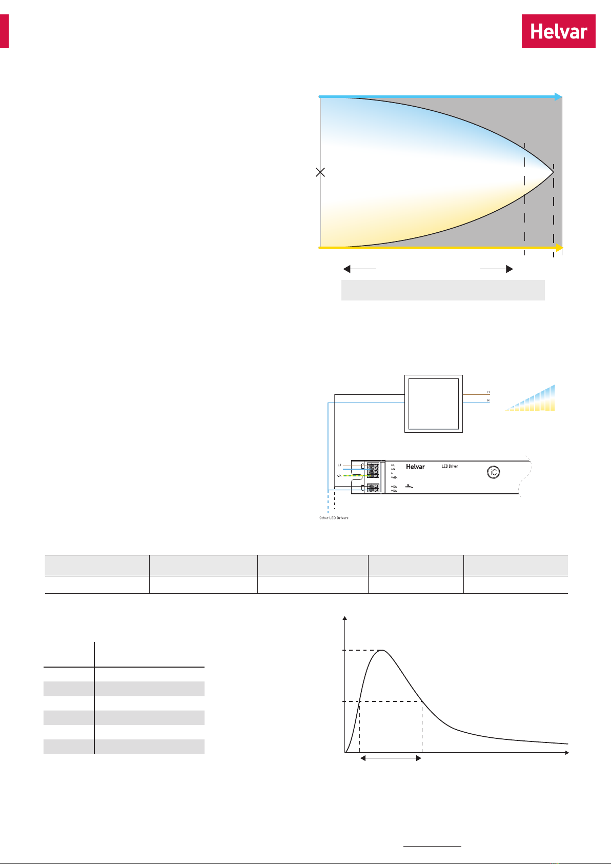
Cool white
Warm white
High DYNAMIC Low
10 %
2 %100 %
Recommended dimming range
depending on the application
Intensity dimming range 100 - 1 %
Not
achievable
Factory
setting
• The LL60/2-E-DA-iC driver has 2 output channels used to control
the intensity and temperature of white colour as well known as
“Tunable White”
• These drivers respond to DALI type 8 (DT8) commands, which in
practice means that they only have 1 common address for both
output channels
• The tunable white level of intensity and colour temperature can be
set either with a DALI command or by Switch-Control
• The driver will operate correctly once tunable white LED module
parameters are programmed to the driver. Use “Helvar DALI
Driver Configurator” for the parameter setting
• Default LED module parameters are set according to Helvar iC
LED module specifications
• See Helvar DALI Driver Configurator user guide for more
information how to set the parameters to the driver
Tunable white functionality
Switch-Control with tunable white
N
Switch-Control
0
I
Color temperature
and intensity control
Retractive Switch
Helvar iC drivers provide the simplest form of control in tunable white
with Helvar patented single switch Switch-Control functionality. With
single push button the user is able to control both the light intensity
and colour temperature to the desired level. The system synchronises
the light levels and CCTs every time the colour temperature is
adjusted to ensure pleasant user experience and uncompromised
lighting comfort. More information about the functionality can be
found in Switch-Control user guide at www.helvar.com.
27.11.2018 3/6
LL60/2-E-DA-iC
T22 043 1C

Helvar |Helvar Oy Ab, Keilaranta 5 FI-02150 Espoo, Finland. Data is subject to change without notice. www.helvar.com
CH1
(Cool white)
CH2
(Warm white)
R
L
N
DA
DA
Connections
Note:
• Not suitable for load side switching operation
• Label may differ if the unit is preset to fixed current
• Switch-Control with this driver is only allowed to be used in Class I luminaires
Dimensions (mm)
35
4.5
369.5
380
370
21
Connections and Mechanical Data
Wire size 0.5 mm2 –1.5 mm2
Wire type Solid core and fine-stranded
Wire insulation According to EN 60598
Maximum driver to LED wire length 5 m
Weight 365 g
IP rating IP20
NTC trigger point 8.2 kΩ
Resistor (Ω) 0 1k 1,8k 2,74k 3,3k 4,7k 6,8k 8,2k 10k 15k 22k 39k 100k Open
Iout (mA) 700 650 620 600 580 550 520 500 480 450 430 400 370 350
Order code T70000 T70102 N/A T72741 T70332 T70472 T70682 T70822 T70103 N/A N/A N/A N/A N/A
Iset current setting resistor values
T22 043 1C
Output current can be set with the current setting resistor connected to the Iset terminal. Example current and resistor values across
the range can be found in the following table. More information about the current setting resistor is given on page 5.
27.11.2018 4/6
LL60/2-E-DA-iC

Helvar |Helvar Oy Ab, Keilaranta 5 FI-02150 Espoo, Finland. Data is subject to change without notice. www.helvar.com
LL60/2-E-DA-iC LED driver is suited for built-in usage in luminaires. With LL1x2135-SR strain reliefs, independent use is possible too (see
the LL1x2135-SR datasheet for details). In order to have safe and reliable LED driver operation, the LED luminaires will need to comply
with the relevant standards and regulations (e.g. IEC/EN 60598-1). The LED luminaire shall be designed to adequately protect the LED
driver from dust, moisture and pollution. The luminaire manufacturer is responsible for the correct choice and installation of the LED
drivers according to the application and product datasheets. Operating conditions of the LED drivers may never exceed the specifications
as per the product datasheet.
Installation & operation
Maximum ambient and tctemperature
• For built-in components inside luminaires, the taambient
temperature range is a guideline given for the optimum
operating environment. However, integrator must always
ensure proper thermal management (i.e. mounting base of the
driver, air flow etc.) so that the tcpoint temperature does not
exceed the tcmaximum limit in any circumstance.
• Reliable operation and lifetime is only guaranteed if the
maximum tcpoint temperature is not exceeded under the
conditions of use.
Current setting resistor
LL60/2-E-DA-iC LED driver features a constant current output
adjustable via current setting resistor.
• An external resistor can be inserted in to the current setting
terminal, allowing the user to adjust the LED driver output
current
• When no external resistor is connected, then the LED drivers will
operate at their default lowest current level
• A standard through-hole resistor can be used for the current
setting. To achieve the most accurate output current it is
recommended to select a quality low tolerance resistor.
Minimum diameter for resistor leg is 0.51mm.
• Always connect the current setting resistor only into the
terminals marked with Iset on the LED driver label.
• For the resistor/current value selection, refer to the table on
page 4.
LED driver earthing
• LED drivers are designed to support different luminaire
classifications, such as Class I or Class II fittings (no earth
required). LL60/2-E-DA-iC is Class II driver and suitable for
Class I and II luminaires, as well as driving SELV Class III
luminaires in independent installation with strain reliefs.
• As Class II driver, LL60/2-E-DA-iC does not need the earth
connection for electrical safety. To improve e.g. EMC
performance, functional earth can be connected.
Miniature Circuit Breakers (MCB)
• Type-C MCB’s with trip characteristics in according to EN 60898
are recommended.
• Please see more details in “MCB information” document in each
driver product page in “downloads & links” section.
Use of Switch-Control functionality
• Maximum numbers of LED drivers to be connected to one switch
is 30.
• The maximum cabling length from the switch to the driver is 25
meters. If longer cabling is needed, please connect a capacitor
across the Switch-Control input (1 μF, min. 275 VAC RMS and X2
rated, according to IEC 60384-14).
• Ensure that all components connected to Switch-Control circuitry
are mains rated.
• Switch-Control with this driver is only allowed to be used in Class
I luminaires
• More information in Switch-Control User Guide at www.helvar.
com.
Helvar Driver Configurator support
LL60/2-E-DA-IC LED driver is supported by Helvar Driver
configurator software. The configurator allows user to control and
set the parameters for tunable white such as colour temperature
limit and lumen output on both channels. The linear dimming curve
can be enabled from the configurator as well.
Information and conformity
T22 043 1C 27.11.2018 5/6
Helvar |Helvar Oy Ab, Keilaranta 5 FI-02150 Espoo, Finland. Data is subject to change without notice. www.helvar.com
Conformity & standards
General and safety requirements EN 61347-1
Particular safety requirements for DC
or AC supplied electronic control gear
for LED modules
EN 61347-2-13
Thermal protection class EN 61347, C5e
Mains current harmonics EN 61000-3-2
Limits for voltage fluctuations and
flicker
EN 61000-3-3
Radio frequency interference EN 55015
Immunity standard EN 61547
Performance requirements EN 62384
Digital addressing lighting interface:
General requirements for DALI system
Requirements for DALI control gear
Requirements for control gear of LED
modules
Particular requirements for control
gear - Colour control (Dali Device Type
8)
EN 62386-101
EN 62386-102
EN 62386-207
EN 62386-209
Compliant with relevant EU directives
RoHS / REACH compliant
ENEC and CE marked
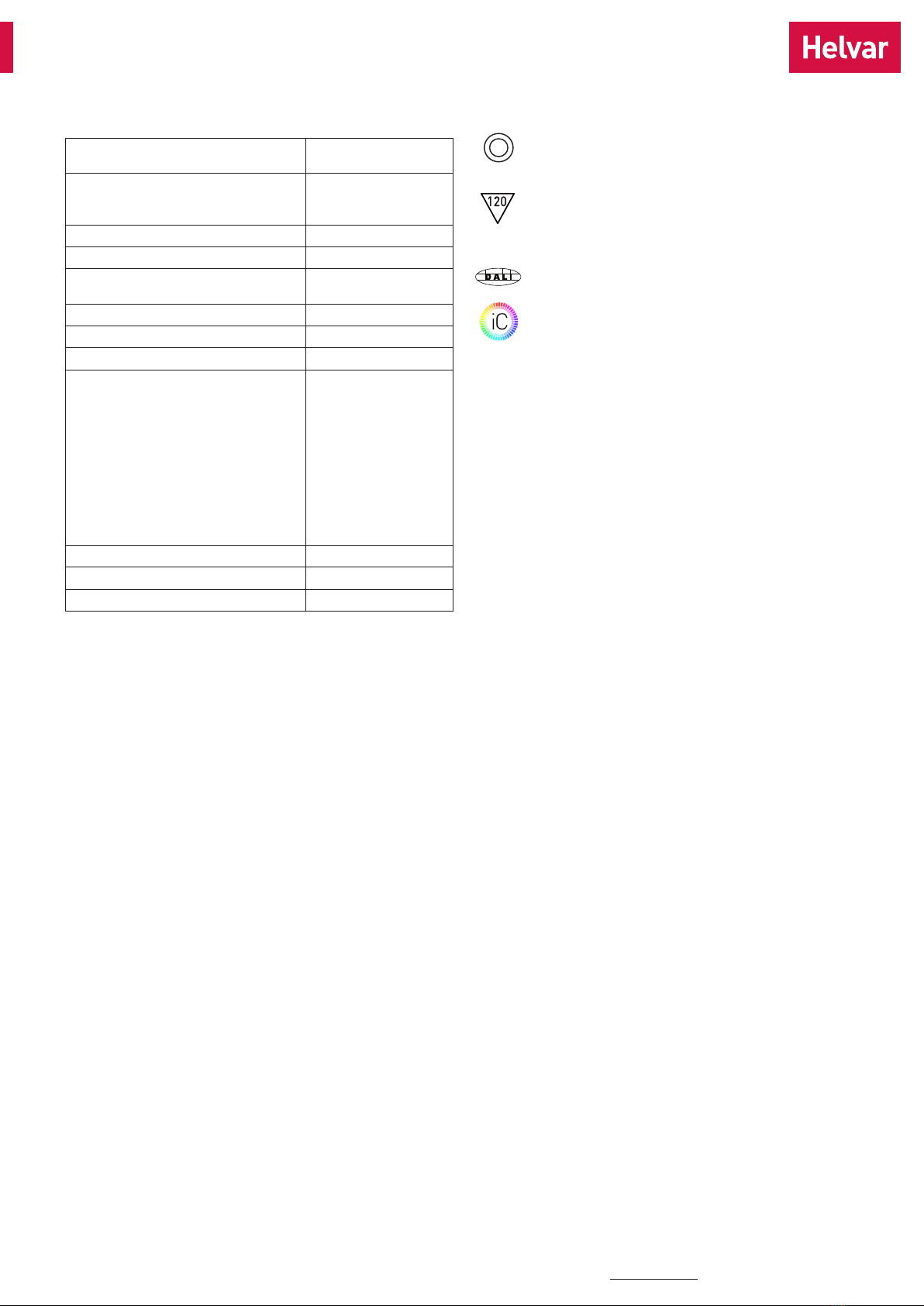
Label symbols
Double insulated controlgear suitable for built-in use.
Thermally controlled control gear, incorporating means
of protection against overheating to prevent the case
temperature under any conditions of use from exceeding
120 °C.
DALI certified control gear.
Helvar Intelligent Colour drivers providing DALI colour
control (tunable white) functionality.
Information and conformity
T22 043 1C 27.11.2018 6/6
This manual suits for next models
1
Table of contents
Other HELVAR DC Drive manuals


Popular DC Drive manuals by other brands


Siemens
Siemens SIDOOR AT12 System manual

Rockwell Automation
Rockwell Automation Reliance electric GV3000/SE user guide

Superior
Superior SLO-SYN SS2000MD4 installation instructions

Siemens
Siemens simovert masterdrives operating instructions

Panasonic
Panasonic JU-475-4 Service manual

RTA
RTA X-PLUS ET B4 Series instruction manual