CONTENTS
PART I Page
1. INTRODUCTION ...................................................................................................................................................................... 1
2. MODELS AND MODEL NUMBERS ...................................................................................................................................... 1
2.1 5.25inch FDD Series................................................................................................................ 1
3. SPECIAL TOOLS ...................................................................................................................................................................... 1
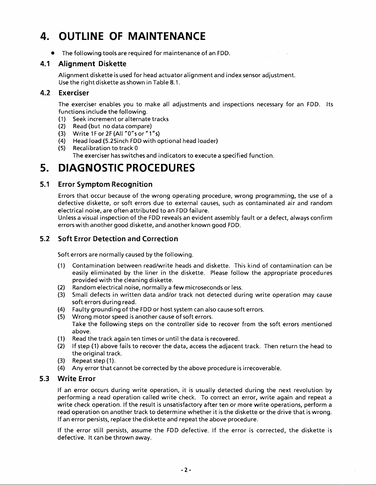
4. OUTLINE OF M AINTE NAN CE................................................................................................................................................ 2
4.1 Alignment Diskette ................................................................................................................................. 2
4.2 Exerciser .................................................................................................................................................... 2
5. DIAGNOSTIC PROCEDURES .................................................................................................................................................. 2
5.1 Error Symptom Recognition .................................................................................................................... 2
5.2 Soft Error Detection and Correction ....................................................................................................... 2
5.3 Write Error ................................................................................................................................................. 2
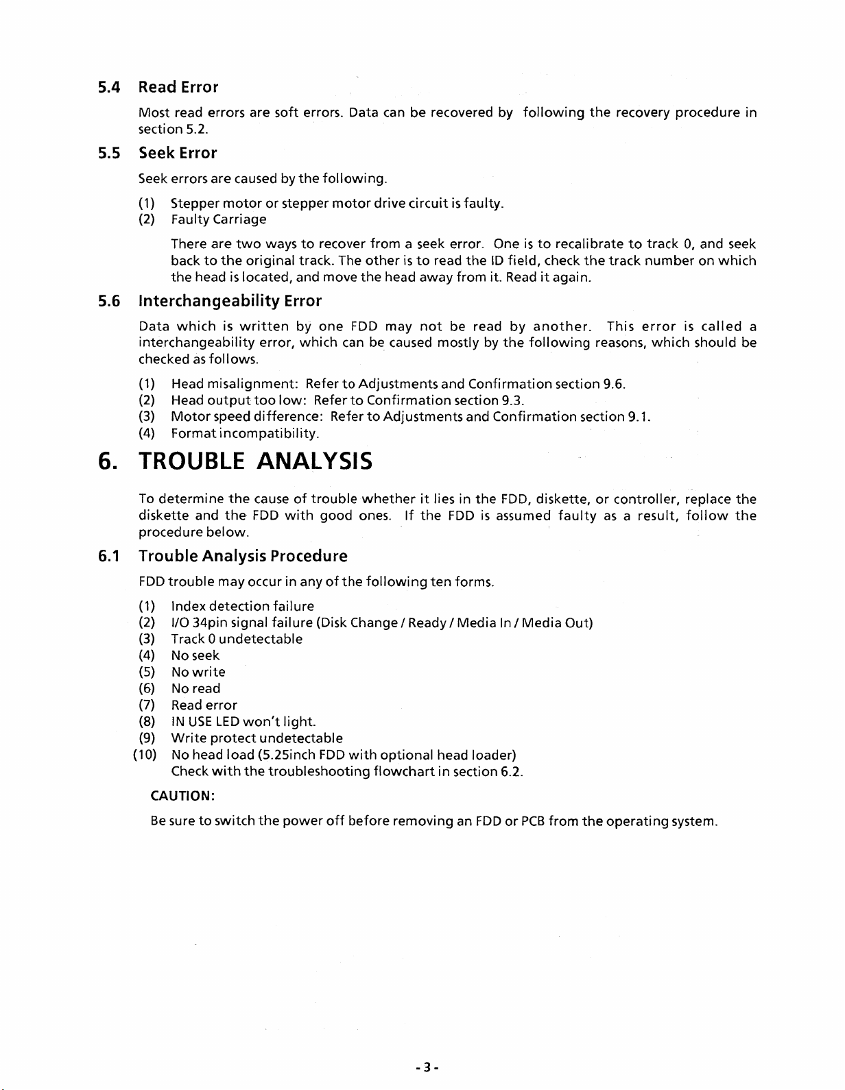
5.4 Read Error .................................................................................................................................................. 3
5.5 Seek Error .................................................................................................................................................. 3
5.6 Interchangeability Error .......................................................................................................................... 3
6. TROUBLE ANALYSIS .............................................................................................................................................................. 3
6.1 Trouble Analysis Procedure .................................................................................................................... 3
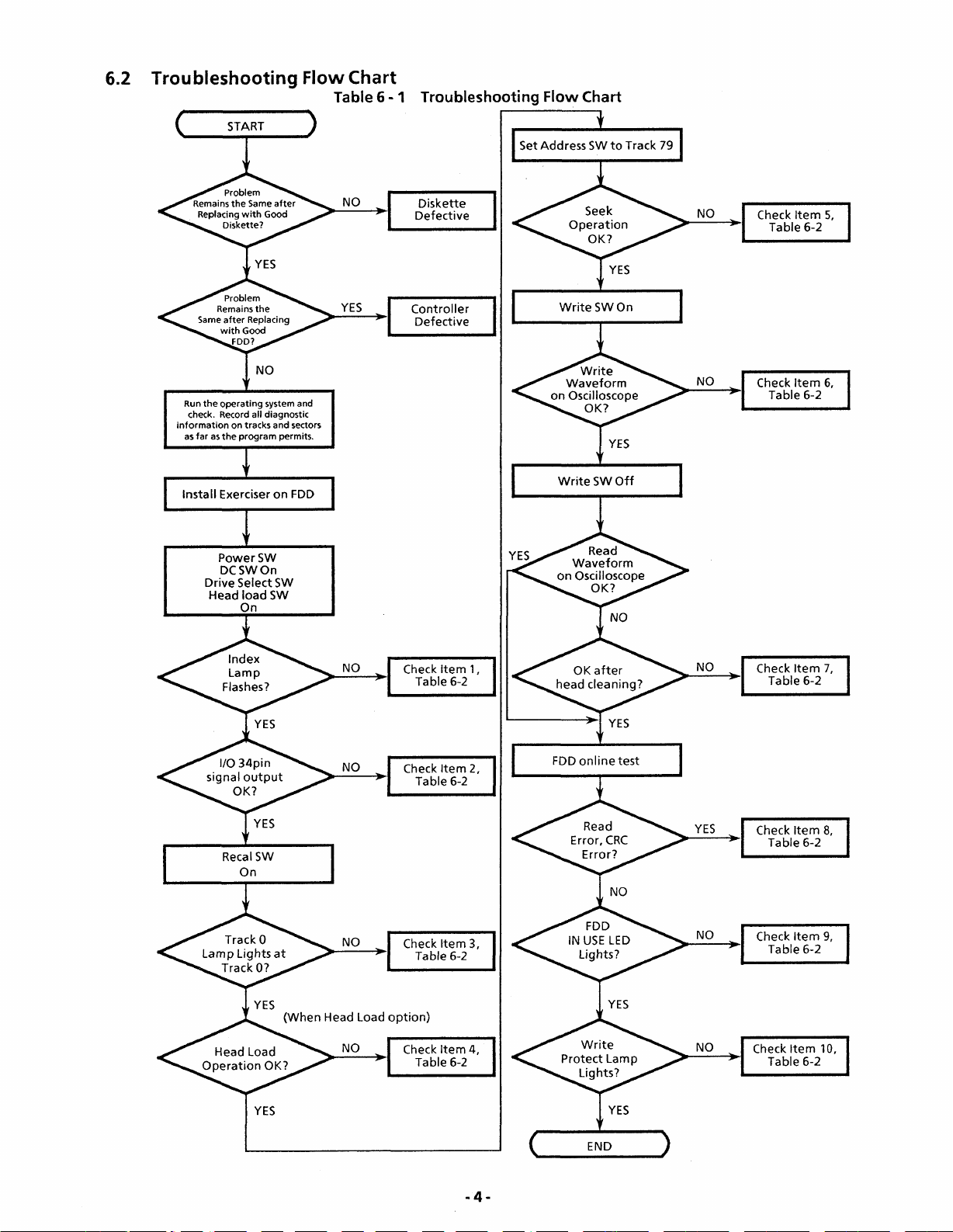
6.2 Troubleshooting Flowchart .................................................................................................................... 4
6.3 Trouble Analysis Table .............................................................................................................................. 5
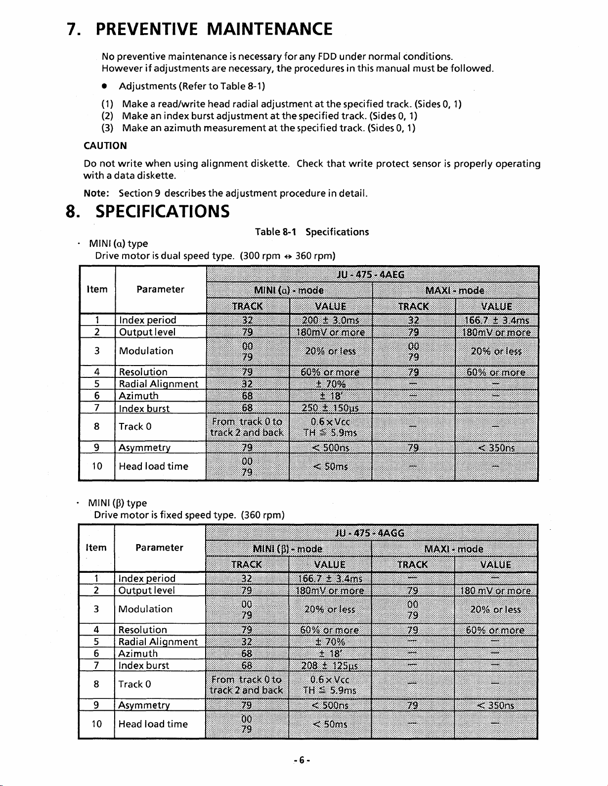
7. PREVENTIVE MAINTENANCE .............................................................................................................................................. 6
8. SPECIFICATIONS .................................................................................................................................................................... 6
9. ADJUSTMENTS AND VERIFICATIONS ................................................................................................................................ 7
9.1 Motor Speed Verification (Index Period) ................................................................................................ 7
9.2 Write Protect Verification ........................................................................................................................ 7
9.3 Head Output Verification ........................................................................................................................ 7
9.4 Output Modulation Verification ............................................................................................................. 8
9.5 Resolution Verification
........................................................................
8
9.6 Radial Alignment Verification and Adjustment
....................................................................................
8
9.7 Azimuth Verification ............................................................................................................................... 9
9.8 Index Burst Verification and Adjustment .............................................................................................. 10
9.9 Track 0 Sensor Adjustment ...................................................................................................................... 10
9.10 Asymmetry Verification ............................................................................................................................ 11
10. TEST P O IN TS ............................................................................................................................................................................ 12
11. PANASONIC ALIGNMENT DISKETTE .................................................................................................................................. 13
PART II
12. REMOVALS AND INSTALLATIONS ...................................................................................................................................... 14
12.1 PCB Removal and Installation ................................................................................................................... 14
12.2 Front Plate and Handle Removal and Installation ................................................................................. 14
12.3 Track 0 Sensor Removal and Installation ................................................................................................ 15
12.4 Collet Assembly Removal, Installation, and Adjustment
.....................................................................
15
12.5 Clamp Assembly Removal and Installation ............................................................................................ 16
12.6 Write Protect Sensor Assembly and Index Sensor Assembly Removal and Installation
.....................
16
12.7 Cartridge Guide Assembly Removal and Installation ........................................................................... 17
12.8 Stepper Motor Assembly Removal and Installation ............................................................................. 18
12.9 Head Carriage Assembly Removal and Installation ............................................................................. 18 — 19
12.10 Drive Motor Removal and Installation ........................................................................... 20
12.11 LED Assembly Removal and Installation ................................................................................................ 21
12.12 Lifter Unit Removal and Installation ....................................................................................................... 21
12.13 Media Lifter Removal and Installation .................................................................................................... 22
12.14 Media Sensor Assembly Removal and Installation ................................................................................. 22
13. EXPLODED VIEW .................................................................................................................................................................... 23
14. REPLACEMENT PARTS LIST .................................................................................................................................................. 24
15. REPLACEMENT PARTS LIST FOR PCB .................................................................................................................................. 2 5 - 2 6
16. SCHEMATIC DIAGRAM ........................................................................................................................................................ 27
17. CIRCUIT BOARD ...................................................................................................................................................................... 2 8 -2 9
18. BLOCK DIAGRAM .................................................................................................................................................................. 30
- i -