AuCom MVH 2.0 Series User manual

READTHESEINSTRUCTIONS BEFOREUSE!
Variable frequency drive (VFD)
Medium voltage 2.3kV 13.8kV
User Manual en
MVH 2.0 Series
de

IMPRINT
IMPRINT
Publisher
AuCom MCS GmbH & Co. KG
Borsigstraße 6
49324 Sendenhorst
GERMANY
Phone: +49 2526 93880 0
Internet: www.aucom.com
Document reference, date of creation
MVH2.0_BA_1.0.0_en 26.10.2023
Validity
Product: MVH2.0 SERIES
Copyright
© 2023 AuCom Electronics Ltd. All Rights Reserved.
As AuCom is continuously improving its products it reservesthe right to modify or change the specificationof its products
at any time without notice. The text, diagrams, images and any other literary or artistic works appearing in this document
are protected by copyright. Users may copy some of the material for their personal reference but may not copy or use
material for any other purposewithout the prior consent of AuCom Electronics Ltd. AuComendeavours to ensure that the
information contained in this document including images is correct but does not accept any liability for error, omission or
differences with the finished product.

INTRODUCTION
3/254 USER MANUAL MVH2.0_BA_1.0.0_en MVH2.0
INTRODUCTION
GENERAL INFORMATION
Model: MVH2.0 Series
Product type: Speed regulation and control of medium
voltage three-phase motors
Product group: Variable frequency drive (VFD)
AuCom MCS GmbH & Co. KG
Borsigstraße 6
49324 Sendenhorst
GERMANY
Phone: +49 2526 93880 0
Internet: www.aucom.com
Support: www.aucom.com/contact-us/support-enquiry
Title: MVH2.0 Series
Document type: User Manual
Document reference: MVH2.0_BA_1.0.0_en
Document part number: 710-25096-00C
Hardware Main control unit: as of version HC4
Hardware I/O Interface unit: as of version HC4
Hardware Operating unit (HMI): as of version TPC1031Kt
Firmware Main control unit: as of version 2.27.10
Firmware I/O Interface unit: as of version 2.27.10
Firmware Operating unit (HMI): as of version 2.27.10
Tab. 1-1 MVH2.0 User Manual Change log
PRODUCT IDENTIFICATION
MANUFACTURER
DOCUMENT INFORMATION
VALIDITY
CHANGE LOG
Version
Change
Initiator
Date
1.0.0
Initial version
AuCom, (FB)
26.10.2023
INTRODUCTION
MVH2.0 USER MANUAL MVH2.0_BA_1.0.0_en 4/254
NOTES ON THIS USER MANUAL
This document contains important information for safe, effective, and efficient use of the
MVH2.0 variable frequency drive (VFD).
The source user manual was written in German language.
This user manual is an integral part of the MVH2.0 product and must always be kept in
the immediate vicinity of the MVH2.0 frequency inverter.
This user manual is intended for the personnel responsible for the installation,
commissioning,
and
maintenance
of the product. You can find further information on
qualification requirements and access level 1.3 Target
Audience and Qualification
Chapter 1 Safety
General safety instructions relevant to the product.
Chapter 2 Product Overview
Basic information on the MVH2.0 frequency inverter and its intended use.
Chapter 3 Structure and Functions
Mechanical and electrical design of the VFD cabinet and its main components as well as
functional outline of the MVH2.0.
Chapter 4 Operating and Display
Presentation and explanation of all relevant elements for the initial commissioning and
operation of the MVH2.0.
Chapter 5 VFD Operation
Presentation and explanation of the MVH2.0 operating functions for effective and efficient
operation.
Chapter 6 Maintenance
Measures for planning and carrying out maintenance work to maintain the MVH2.0 target
state and optimise its availability.
Chapter 7 Troubleshooting
Information on causes and remedial measures of potential malfunctions as well as
instructions for restoring the MVH2.0 to its target state.
Chapter 8 Transport, Storage, and Installation
Information and instructions on maintaining the MVH2.0 in its intended condition during
transport and storage as well as general installation instructions.
Chapter 9 Disposal
Instructions for the proper and environmentally friendly disposal of the MVH2.0 after final
decommissioning.
Chapter 10 Spare Parts
Ordering information on available spare parts and accessories for the MVH2.0 product.
SOURCE USER MANUAL
STORAGE
TARGET AUDIENCE
CHAPTER OVERVIEW
INTRODUCTION
5/254 USER MANUAL MVH2.0_BA_1.0.0_en MVH2.0
SYMBOLS AND REPRESENTATIONS
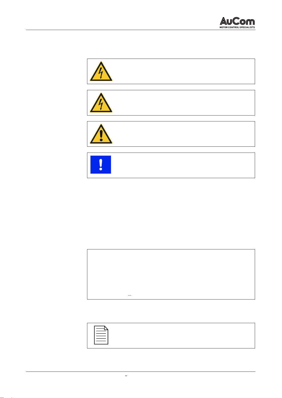
In this user manual, safety and protection levels are classified as DANGER, WARNING,
CAUTION and NOTICE.
DANGER
Warns of an electric shock hazard with a high degree of risk which, if
not avoided, may result in death or serious injury.
WARNING
Warns of an electric shock hazard with a medium degree of risk which,
if not avoided, may result in death or serious injury.
CAUTION
Warns of a hazard (general hazard location) with a low degree of risk
which, if not avoided, may result in minor or moderate injury.
NOTICE
Warns of situations that can lead to property damage if not avoided.
If several different levels of hazards are combined in one warning, the highest level of
warningisalwaysselected. Warningsaboutpersonalhazardsmayincludewarningsabout
property damage.
The warnings used in this user manual are each indicated by:
a warning symbol,
a signal word to indicate the extent of the hazard,
an indication of the nature and source of the hazard,
an indication of the possible consequences if the hazard is not avoided, and
the measures to be taken to avoid the hazard.
Warning
symbol
Signal word
Nature and source of the hazard
Possible consequences of not avoiding the hazard.
➢Measure 1 to be taken to avoid the hazard
➢Measure 2 to be taken to avoid the hazard
➢
In this user manual, additional information of a general nature or for more detailed
information on specific matters is given as a NOTE or as a DISPOSAL NOTE.
NOTE
Indicates specific information relating to the use or operation of the
product.
In this user manual, instructions for proper and environmentally friendly disposal are
shown as DISPOSAL NOTES
WARNINGS
WARNING STRUCTURE
INFORMATIVE NOTES
NOTES ON DISPOSAL

INTRODUCTION
MVH2.0 USER MANUAL MVH2.0_BA_1.0.0_en 6/254
To increase the efficiency of this user manual, reference is made to exemplary
instructions or further chapters for the description of the same procedure or further
information.
CHAPTER REFERENCE
➢Indication of the process/topic as well as indication of the
referenced chapter number and the chapter title.
The
beginning
of a
general
instruction sequence on how to perform an action sequence is
introduced as follows:
INSTRUCTION Title of the instruction
START
The
beginning
of an instruction sequence
with indication of the required authorisation
(user level)
to perform an action sequence is introduced as follows:
INSTRUCTION Title of the instruction
START
USER LEVEL:
The action steps of the action sequence of an instruction are indicated as follows:
STEP 1:
➢Result 1 of the first action step
➢Result 2 of the first action step
➢
STEP 2:
➢Result 1 of the second action step
➢Result 2 of the second action step
➢
The end of a general or specific instruction sequence is indicated as follows
END
In this user manual,
italics
are used for names of:
Parameters and functions,
Parameter setting options,
Alarm and fault messages, and
Common terms of particular importance.
DISPOSAL NOTE
Indicates the regulations for the disposal of old electrical appliances.
REFERENCES
LABELLING OF INSTRUCTIONS
TYPOGRAPHIC CONVENTIONS

TABLE OF CONTENTS
7/254 USER MANUAL MVH2.0_BA_1.0.0_en MVH2.0
TABLE OF CONTENTS
Imprint..........................................................................................................................................................................................2
Introduction..................................................................................................................................................................................3
General Information ...........................................................................................................................................................3
Notes on this User Manual.................................................................................................................................................4
Symbols and Representations ...........................................................................................................................................5
Table of Contents.........................................................................................................................................................................7
List of Abbreviations..................................................................................................................................................................10
1Safety.................................................................................................................................................................................11
1.1 Warning Signs on the VFD Cabinet.........................................................................................................................11
1.2 Intended Use............................................................................................................................................................11
1.3 Target Audience and Qualification .........................................................................................................................12
1.4 Safety Instructions ..................................................................................................................................................13
1.4.1 Five Safety Rules of Electrical Engineering .............................................................................................13
1.4.2 Safe Operation...........................................................................................................................................13
2Product Overview..............................................................................................................................................................16
2.1 Important Notes on the Product.............................................................................................................................16
2.1.1 MVH 2.0 MV Frequency Inverter Overview................................................................................................18
2.1.2 Hazardous Areas .......................................................................................................................................21
2.1.3 Conformity .................................................................................................................................................22
2.1.4 Labelling of the Product............................................................................................................................24
2.2 Product Data............................................................................................................................................................31
2.2.1 Features of the MVH 2.0............................................................................................................................31
2.2.2 Dimensions and Weights...........................................................................................................................33
2.2.3 Environment ..............................................................................................................................................33
2.2.4 Technical Data...........................................................................................................................................35
2.3 Scope of Supply.......................................................................................................................................................36
2.3.1 Air-Cooled VFD Cabinets...........................................................................................................................36
3Structure and Functions...................................................................................................................................................37
3.1 Principles of the Procedure....................................................................................................................................37
3.2 Mechanical Structure..............................................................................................................................................45
3.2.1 ACC AuCom Compact Cabinet: Front Side Service Zone......................................................................45
3.2.2 AFA AuCom Front Access: Front Side Service Zone.............................................................................47
3.2.3 ADA AuCom Double Access: Double Side Service Zone.......................................................................50
3.3 Safety and monitoring equipment..........................................................................................................................53
3.3.1 EMERGENCY STOP....................................................................................................................................53
3.3.2 Cabinet door Interlockings........................................................................................................................55
3.3.3 Crank Access Interlock for Disconnector/Earthing Switch.....................................................................56
3.3.4 Earthing Concept of MVH 2.0 ....................................................................................................................58
3.4 Multi-Level Transformer ........................................................................................................................................60
3.5 VFD Control System................................................................................................................................................63

TABLE OF CONTENTS
MVH2.0 USER MANUAL MVH2.0_BA_1.0.0_en 8/254
3.5.1 VFD Control Unit Assemblies.................................................................................................................63
3.5.2 I/O Interface Unit (PLC) for Inputs and Outputs.......................................................................................69
3.5.3 Operating Unit HMI (Touchscreen)...........................................................................................................84
3.6 Power Cell ...............................................................................................................................................................86
3.6.1 Power Cell Components............................................................................................................................86
3.6.2 Power Cell Electrical Operating Principle................................................................................................89
3.6.3 Power Cell Control Board.........................................................................................................................90
3.6.4 Power Cell Gate Drive Board ....................................................................................................................92
4Operating and Display ......................................................................................................................................................93
4.1 Overview...................................................................................................................................................................93
4.2 Alarm Indications....................................................................................................................................................94
4.3 Control and Display Components...........................................................................................................................94
4.3.1 EMERGENCY STOP Switch........................................................................................................................94
4.3.2 Disconnector/Earthing Switch: Key Switch, Crank Access, and Crank Handle......................................94
4.3.3 MV Main Switch Element (Medium Voltage).............................................................................................95
4.3.4 START/STOP Buttons on the HMI .............................................................................................................96
4.3.5 RESET Components...................................................................................................................................96
4.3.6 Fault Indications........................................................................................................................................97
4.3.7 Operating Unit (HMI)..................................................................................................................................98
4.4 Operating Modes and VFD Modes...........................................................................................................................98
4.5 General Operating Instructions..............................................................................................................................99
4.5.1 Switching the VFD ON and OFF (Standby)................................................................................................99
4.5.2 Start page and Standby page ..................................................................................................................102
4.5.3 Menu Structure........................................................................................................................................105
4.5.4 Menu Navigation......................................................................................................................................106
4.5.5 User Levels..............................................................................................................................................107
4.5.6 Changing Parameter Settings (General)................................................................................................112
4.5.7 Selecting the Menu Language ................................................................................................................117
4.6 Main Menu (HMI) ...................................................................................................................................................119
4.6.1 Main menu: VFD Monitor.........................................................................................................................119
4.6.2 Main Menu: Trend Recorder...................................................................................................................122
4.6.3 Main Menu: Parameter Setup.................................................................................................................134
4.6.4 Main Menu: Event Recorder....................................................................................................................180
4.6.5 Main Menu: Power Cell Status................................................................................................................183
4.6.6 Main Menu: Other Settings .....................................................................................................................184
5VFD Operation.................................................................................................................................................................203
5.1 Operating Functions..............................................................................................................................................203
5.1.1 Extended U/f-Control ..............................................................................................................................203
5.1.2 Asynchronous Motor Open Loop Vector Control.................................................................................203
5.1.3 Synchronous Motor Open Loop Vector Control...................................................................................205
5.1.4 Synchronous Transfer.............................................................................................................................205

TABLE OF CONTENTS
9/254 USER MANUAL MVH2.0_BA_1.0.0_en MVH2.0
5.1.5 Master/Slave Control Functions.............................................................................................................206
5.1.6 Speed Start / VFD Start at Rotating Motor.............................................................................................208
5.1.7 Motor Reverse Operation........................................................................................................................208
5.1.8 MV Mains Failure (MV Loss)....................................................................................................................215
5.1.9 Motor Overload Protection (Thermal Replica) .......................................................................................216
5.1.10 Automatic Ramp Intervention.................................................................................................................217
5.1.11 Bypassed Operation (VFD Bypass)..........................................................................................................219
5.1.12 Bypassed Operation (Power Cell Bypass) ..............................................................................................219
6Maintenance....................................................................................................................................................................223
6.1 Routine Inspection ................................................................................................................................................223
6.2 Regular Maintenance............................................................................................................................................224
6.3 Maintenance of Spare Power Cells ......................................................................................................................225
7Troubleshooting..............................................................................................................................................................226
7.1 Alarm/Fault Causes and Remedy......................................................................................................................226
7.1.1 Alarm Messages......................................................................................................................................226
7.1.2 Fault Messages........................................................................................................................................232
7.2 Replacement..........................................................................................................................................................243
7.2.1 Power Cell Replacement.........................................................................................................................243
8Transport, Storage, and Installation..............................................................................................................................245
8.1 Receiving Inspection .............................................................................................................................................245
8.2 Storage...................................................................................................................................................................245
8.3 Transport...............................................................................................................................................................245
8.3.1 Handling during Transport......................................................................................................................245
8.4 Installation.............................................................................................................................................................249
9Disposal...........................................................................................................................................................................251
10 Spare Parts.....................................................................................................................................................................252
Index.........................................................................................................................................................................................253
SAFETY
MVH2.0 USER MANUAL MVH2.0_BA_1.0.0_en 10/254
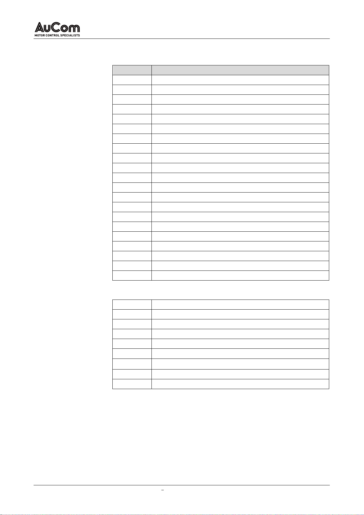
LIST OF ABBREVIATIONS
Acronym
Description
ACC
AuCom Compact Cabinet
AFA
AuCom Front Access
ADA
AuCom Double Access
AI
analog input
AO
analog output
DCS
distributed communication system
DI
digital input
DO
digital output
FE
functional earth
FRT
fault ride through
HMI
human machine interface
IGBT
insulated-gate bipolar transistor
I/O
inputs/outputs
LV
low voltage
MV
medium voltage
NO
normal open
NC
normal closed
PE
protective earth
PLC
programmable logic controller
[pu]
per unit
VFD
variable frequency drive
VC
vector control
Phase angle difference
f
frequency
I
el. current
n
speed
temperature
Rs
stator resistance
U
el. voltage
corresponds to
ABBREVIATIONS
SYMBOLS USED IN FORMULAS
SAFETY
11/254 USER MANUAL MVH2.0_BA_1.0.0_en MVH2.0
1SAFETY
To use the MVH2.0 product safely, you must read, understand, and observe all the
information in this user manual before use. This user manual must always be available
when working on and with the product.
MVH2.0 frequency inverters are designed so that no hazards arise when the product is
used in accordance with the given instructions. However, operation of the MVH2.0
requiresthefrequencyinverterto be connectedtomediumvoltage.Therefore,dangerous,
high voltages are present in the VFD cabinet, which can lead to personal hazards and
damage of the system if the product is not used as intended.
This chapter includes al safety-related information for safe use of the product.
Technical training is available for all personnel involved in the operation and maintenance
of the equipment. For more information, contact AuCom or your local supplier.
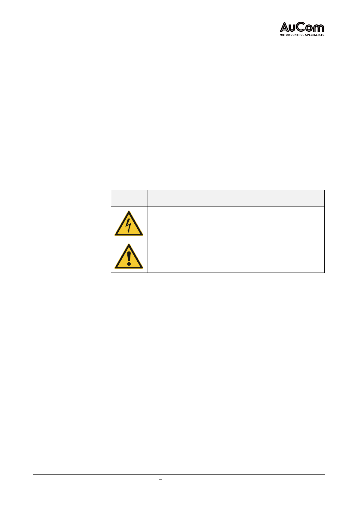
1.1 WARNING SIGNS ON THE VFD CABINET
The following warning signs are attached to the MVH2.0 cabinet and must be observed:
Warning
sign
Description
➢Indicates a hazardous location with an electric shock hazard.
➢General reference to a hazardous point with reference to the
relevant documentation.
1.2 INTENDED USE
MVH2.0 frequency inverters are used for stepless speed control of three-phase drives
(asynchronous and synchronous motors) on the medium voltage level (2.3kV to 13.8kV).
This user manual serves as a specification for the intended use of the product and must
be strictly adhered to. The user manual must be available for all activities connected with
the product.
Only appropriately qualified and authorised personnel can carry out work on and with the
product during the entire product life cycle.
You must observe and comply with all instructions and relevant technical data on
transport and storage conditions.
Atalltimes,you mustobserve theregulationsontheuse of personalprotective equipment
(PPE).
You must comply with all applicable country-specific, local, and industry-specific
ordinances and regulations for the safety and construction of the plant.
You must observe and comply with all instructions and information on ambient conditions
and installation conditions.
GENERAL UNDERSTANDING OF
SAFETY
SAFETY PRECAUTIONS
QUALIFIED AND AUTHORISED
PERSONNEL
TRANSPORT AND STORAGE
PERSONAL PROTECTIVE
EQUIPMENT
PLANT CONSTRUCTION
ENVIRONMENT AND
INSTALLATION
SAFETY
MVH2.0 USER MANUAL MVH2.0_BA_1.0.0_en 12/254
All components of the application (frequency inverter, drive, power supply and its fuse
protection) must be coordinated with each other regarding their rated variables, their
function, and all parameter settings.
Modification or manipulation of the MVH2.0 is not permitted.
Modification or tampering with the MVH2.0 means that the product is being used outside
of its specification and is therefore a non-intended use, which can cause personal injury
and damage to the system. Any consequences of improper use of the product are not
covered by AuCom Support and will void the guarantee or warranty. AuCom excludes all
liability for improper use and any consequences that may arise from it.
Any use that does not correspond to the intended use of the MVH2.0 productis considered
misuse.
DANGER
Danger in case of misuse
Misuse of the MVH2.0 can result in death, serious personal injury, and
damage to the equipment.
➢Never operatethe productunless allsafety devicesof the MVH2.0
are functioning properly or are ready for operation.
➢Never operate the product at a voltage level that does not
correspond to the specified VFD input voltage.
➢Never connect drives to the product whose rated voltage and
current are not matched to the rated values of the MVH2.0.
➢Never put the product into operation unless all parameter
settings of the MVH2.0 have been adjusted to the connected drive
and the application.
➢Never modify or manipulate the product with hardware and/or
software components not specified by AuCom.
➢Never use spare parts that are not specified by AuCom.
1.3 TARGET AUDIENCE AND QUALIFICATION
The MVH2.0 Series frequency inverters are intended for use by qualified personnel in
commercial areas of various industries where frequency inverters are used to control the
speed of three-phase medium voltage motors.
This user manual is intended for qualified personnel for the commissioning, operation,
and maintenance of this product. According to their training and experience, qualified
personnel are able to recognise risks when using the product and its applications and to
avert potential hazards to persons and system components.
For commissioning and operation, the product offers four different user levels, each
adapted to different tasks. Each level requires different qualifications and authorisation.
At this user level, the technical personnel have basic technical knowledge for applications
of frequency inverters on the medium voltage level. This user level allows the start/stop
control of MV AC motors via the frequency inverter.
This user level does not require a password to operate the drive. Instructions for the
operating personnel are given in this user manual.
The technical personnel have advanced expertise for applications of frequency inverters
on the mediumvoltage level. This user level allows start/stop control of MV AC motors via
thefrequencyinverter,readingofallparameter settings.Italsolets you programalimited
set of parameters (operation and maintenance).
OPERATION
PRODUCT MODIFICATION AND
DISCLAIMER
MISUSE
USER LEVEL TANDARD
USER LEVEL OPERATOR
SAFETY
13/254 USER MANUAL MVH2.0_BA_1.0.0_en MVH2.0
This user level requires the entry of the corresponding
Operator
password. Instructions
of are carried out based on this user manual as well as MVH2.0-specific training on the
extended application of the product.
The technical personnel have advanced expertise for applications of frequency inverters
on the mediumvoltage level. This user level allowsstart/stop control of MV AC motors via
the frequency inverter as well as reading and setting all parameters (commissioning,
operation, and maintenance).
This user level requires the entry of the corresponding
Engineer
password. The
instruction of the operating personnel is carried out based on the complete technical
documentation as well as training by experts.
This user level is password protected and is the exclusive responsibility of the
manufacturer.
1.4 SAFETY INSTRUCTIONS
1.4.1 FIVE SAFETY RULES OF ELECTRICAL ENGINEERING
For all work on the MVH2.0 you must apply the five safety rules of electrical engineering
according to DIN VDE 0105 in the following order:
1. Switch off
2. Lock against reclosure
3. Check that lines and equipment are dead
4. Ground and short circuit all phases
5. Cover, partition, or screen adjacent line sections
To restart the equipment, follow the five safety rules is done in reverse order.
1.4.2 SAFE OPERATION
WARNING
➢Do not use the VFD if there is moisture in the VFD cabinet, parts
are missing, or parts were damaged during unpacking.
➢If the packing list does not correspond to the model number
indicated on the nameplate you
must not
install the VFD.
➢When transporting or lifting the VFD, make sure that the means
of transport is suitable for the weight and dimensions of the VFD.
If this is not the case, the VFD may be damaged during handling.
CAUTION
➢Follow the instructions in this manual. Installation must only be
carried out by qualified personnel.
➢Install the VFD only on suitable surfaces (metal or concrete) and
away from combustible materials to avoid fire hazard.
➢Do not touch the electronic components inside the VFD cabinet
directly during installation as this may cause electrostatic
damage to the VFD.
USER LEVEL NGINEER
USER LEVEL MANUFACTURER
DELIVERY INSPECTION
INSTALLATION

SAFETY
MVH2.0 USER MANUAL MVH2.0_BA_1.0.0_en 14/254
➢Only install or remove PCBs und ESD-compliant conditions
(antistatic protection).
➢Tighten screws and other parts according to the specified
torques.
➢Make sure that no metal chips, wire debris and other small parts
can enter the VFD cabinet to prevent damage to the VFD during
operation.
WARNING
➢Never connect the phases of the medium voltage (L1, L2, L3) to
the VFD output terminals (2U, 2V, 2W).
➢Electrical connections must only be made by qualified personnel
and in accordance with the relevant standards for electrical work.
➢Make sure that all power supplies and auxiliary voltages are
switched off before wiring to avoid electric shock or fire.
➢Ground the VFD cabinet properly to avoid electrostatic charges.
WARNING
➢Before applying mains supply voltage, make sure that the supply
voltage corresponds to the rated voltage of the VFD.
➢Make sure thatthe main circuit wiringis correctly connected, and
terminal screws are tightened with the specified torques.
➢The VFD must not be energised until the wiring is completed and
the cabinet doors are closed. Never open acabinet door when the
medium voltage supply is switched on to avoid the risk of electric
shock.
➢If
automatic start
after MV loss is enabled, you must take
appropriate safety precautions in the periphery of the VFD to
prevent personnel injury and damage to the property.
➢As soon as the VFD is switched on, the terminals of the VFD are
live. This also applies to stop mode. Do not touch the terminals as
this may cause an electric shock.
➢Do not disconnect the power supply for the fans while the VFD is
in operation as this may cause overheating and damage to the
VFD system. This will also cause the control system to shut down.
➢For water-cooled VFDs, the cooling water supplied by the
customer must meet the specifications.
➢Do not reset a fault message until it the start command has been
disabled. Resetting fault messages when the start command is
active can lead to personal injury and damage to the equipment.
ELECTRICAL CONNECTION
OPERATION

SAFETY
15/254 USER MANUAL MVH2.0_BA_1.0.0_en MVH2.0
WARNING
➢Make sure that the VFD output is isolated and earthed before
starting any work on the VFD.
➢If the load can remain in operation while the VFD is being
serviced, you must isolate the VFD from the motor to avoid
electrical shock.
➢Never troubleshoot or service the VFD with the medium voltage
switchedon.YoumustswitchofftheVFDbeforeopeningacabinet
door and follow all interlocking and safety instructions.
➢To avoid injuries from the residual voltage of the main circuit
capacitors, wait at least 10min after disconnection or failure of
thepower supplyandmake surethatthevoltageindicatorson the
power cells are off before carrying out maintenance and
inspection work.
➢Only qualified personnel can perform maintenance, inspection,
and repair work.
CAUTION
Dispose of all used components or parts properly.
WARNING
You must not modify the VFD. Any modification to the VFD is the sole
responsibility of the manufacturer.
MAINTENANCE AND
INSPECTION
DISPOSAL
OTHERS

PRODUCT OVERVIEW
MVH2.0 USER MANUAL MVH2.0_BA_1.0.0_en 16/254
2PRODUCT OVERVIEW
2.1 IMPORTANT NOTES ON THE PRODUCT
MVH2.0 Series frequency inverters for drives with variable speed offer the following
solutions for the use of medium voltage motors with regard to:
Intelligent control of medium voltage AC synchronous and asynchronous motors
(induction motors)
Motor soft start (extension of motor life cycle)
Motor speed control
Energysavingthroughoptimisedpowerconsumptionofthemotoratdifferentspeed
and power requirements
Reactive power control during motor running
Typical industries:
Chemistry/Petrochemistry
Cement
Mining and Minerals
Water/Wastewater projects
Power generation
Metallurgy
Light industry
Ventilation and air-conditioning technology
Others
Typical application areas:
Power generation
Chemistry/Petrochemistry
Mining and Minerals
Booster fan
Aeration fan
Main fan
Induced draft fan
Induced draft fan
Axial flow fan
Forced draft fan
Forced draft fan
De-scaling pump
Pipeline transportation pump
Water pump
Mud pump
Water injection pump
Sewage pump
Cleaning water pump
Feed water pump
Hot water circulating pump
Feeding pump
Submerged pump
Lift station
Stirring pump
Oil transfer pump
Cleaning water pump
Drainage pump
Brine pump
Water supply pump
Conveyor drive
Circulating water pump
Extruder
Cement
Metallurgy
Municipal projects
Kiln draft fan
Induced draft fan
Booster fan
Kiln gas blower
Forced draft fan
Condensation pump
Separator fan
Blast furnace blower
Slurry pump
Cement mill fan
Blast fan
Water storage pump
Dust removal fan
Converter fan
Circulating water pump
Circulating fan
Electric furnace fan
Boiler feed pump
Grate cooler
Slag-flushing pump
Compressor
Raw mill fan
Feeding pump
Raw material mill
Water-delivery pump
INTENDED USE OF THE VFD
INDUSTRIES
AREAS OF APPLICATION

PRODUCT OVERVIEW
17/254 USER MANUAL MVH2.0_BA_1.0.0_en MVH2.0
Coal mill
Mud pump
Clinker cooler fan
De-scaling pump
Kiln drive
Oxygen compressor
Forced draft fan
Light industry
Others
Gas blower
Pump test stand
Hydraulic pump
VFD power supply test stand
Cleaning pump
Motor test stand
Axial flow pump
Wind channel test
Compressor
Kneading machine
Shredding machine
Tab. 2-1 MVH2.0 Typical areas of application
PRODUCT OVERVIEW
MVH2.0 USER MANUAL MVH2.0_BA_1.0.0_en 18/254
2.1.1 MVH2.0 MV FREQUENCY INVERTER OVERVIEW
The VFD cabinet consists of the following units:
Transformer cabinet,
with multi-level transformer,
Power cell cabinet,
with power cells for the VFD power electronics,
Control/feeder cabinet, with operating elements in the low voltage (LV) section and
connections for mains supply and motor feeder with optional switching and
disconnection devices in the bulkheaded medium voltage section (MV),
Cooling fans for the transformer cabinet and the power cell cabinet.
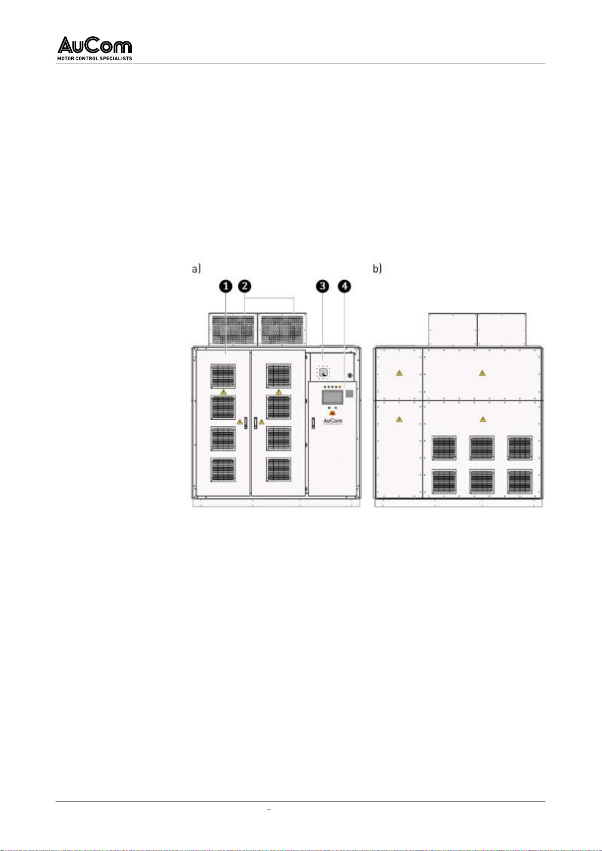
Forfrequencyinverterswith lowerpower (kVA),themulti-leveltransformerandthepower
cells are in a combined cabinet panel. This applies to the following cabinet type:
ACC - AuCom Compact Cabinet
Fig. 2-1 Typical integrated VFD cabinet design: ACC-AuCom Compact Cabinet
a) Front view
b) Rear view
Combined Transformer/Power cell cabinet
Cooling fans
Connection/switching panel (MV)
Control panel with operating and display elements (e.g., operating unit (HMI)
with touchscreen (LV)

PRODUCT OVERVIEW
19/254 USER MANUAL MVH2.0_BA_1.0.0_en MVH2.0
For frequency inverters with higher power (kVA), the multi-level transformer and the
power cells are in separate cabinet panels. This applies to the following cabinet types:
AFA AuCom Front Access, and
ADA AuCom Double Access.
Fig. 2-2 Typical separate VFD cabinet design: AFA-AuCom Front Access
a) Front view
b) Rear view
Transformer cabinet
Cooling fans
Power cell cabinet
Connection/switching panel (MV)
Control panel with operating and display elements (e.g., operating unit (HMI)
with touchscreen (LV)
Optional cable entry for MV supply line from above (customer side)
Optional cable entry for MV motor feeder from above (customer side)

PRODUCT OVERVIEW
MVH2.0 USER MANUAL MVH2.0_BA_1.0.0_en 20/254
Fig. 2-3 Typical separate VFD cabinet design: ADA-AuCom Double Access
a) Front view
b) Rear view
Transformer cabinet
Cooling fans
Power cell cabinet
Connection/switching panel (MV)
Control panel with operating and display elements (e.g., operating unit (HMI)
with touchscreen (LV)
NOTE
The
ADA cabinet type can also be equipped with an:
➢optionalcableentryforMVsupplylinefromabove(customerside),
and an
➢optional cable entry for MV motor feeder from above (customer
side)
Table of contents
Popular DC Drive manuals by other brands

Siemens
Siemens MICROMASTER 430 operating instructions

SOMFY
SOMFY Sonesse 50 RTS Operating and installation guide

YASKAWA
YASKAWA PROFINET V1000 Basic user's guide

SEW-Eurodrive
SEW-Eurodrive MOVIMOT advanced DRN DBC Series operating instructions

Danfoss
Danfoss VLT FC 103 operating instructions

ABB
ABB ACS850-04 series Quick installation guide

Allen-Bradley
Allen-Bradley PowerFlex 6000T Hardware Service Manual

Emerson
Emerson Control Techniques EN Series installation manual

Simu
Simu T5 AUTO Original instructions

Afag
Afag PEZ-52 Maintenance instructions

Lenze
Lenze i510 Series Service manual

LS Industrial Systems
LS Industrial Systems SV-iE5 Series user manual


