HELVAR LC45iC-DA-100-900 User manual
Helvar |Helvar Oy Ab, Keilaranta 5 FI-02150 Espoo, Finland. Data is subject to change without notice. www.helvar.com
Functional Description
• DALI Type 8 compatible. One DALI address for controlling colour temperature by two output channels
• DALI colour type: Colour temperature Tc
• Adjustable constant current output: 100 mA to 900 mA (350 mA default current)
• Current setting programmable via NFC or DALI
• Suitable for flicker-free camera recording applications
• Patented Switch-Control 2 functionality for easy-to-use intensity and colour temperature control with single push button
• Full load recognition with automatic recovery, open and short circuit protection
• Constant Light Output (CLO), adjustable up to 100 000 h (default disabled)
• Energy consumption monitor (real time), running hour monitor (accumulative), energy management (accumulative)
• Memory bank for OEM customer data
Mains Characteristics
Nominal rated voltage range 220 V – 240 V, 0 / 50 – 60 Hz
AC voltage range 198 VAC – 264 VAC
Withstands max. 320 VAC (max. 1 hour)
Withstands min. 176 VAC (max. 1 hour)
DC voltage range 176 VDC –280 VDC
DC starting voltage > 190 VDC
Mains current at full load < 0.24 A
Frequency 0 / 50 Hz –60 Hz
Stand-by power consumption < 0.5 W
THD at full power < 15 %
Tested surge protection 1 kV L-N, 2 kV L-GND (IEC 61000-4-5)
Tested fast transient protection 2 kV (IEC 61000-4-4)
Insulation between circuits & driver case
Mains circuit - SELV circuit Double/reinforced insulation
DALI circuit - SELV circuit Double/reinforced insulation
Mains circuit - DALI circuit Basic insulation
Mains, DALI and output - Driver case Double/reinforced insulation
Mains input - Ground input Basic insulation
Load Output (SELV <60 V)
Output current (Iout) 100 mA –900 mA
Accuracy ± 5 %*
Ripple < 1 %** at ≤ 120 Hz *) At maximum current **) Low frequency, LED load: Cree XP-G LEDs
PstLM < 0.15*
SVM < 0.01* *) At full power, measured with Cree XP-G LED modules.
Uout (max) (abnormal) 60 V
ILED* 100 mA 350 mA (default) 900 mA
PRated* 5 W 17.5 W 45 W
ULED* 12 – 50 V 12 – 50 V 12 –50 V
PF (λ) at full load 0.67 0.89 0.97
Efficiency (η) at full load 66 % 83 % 88 %
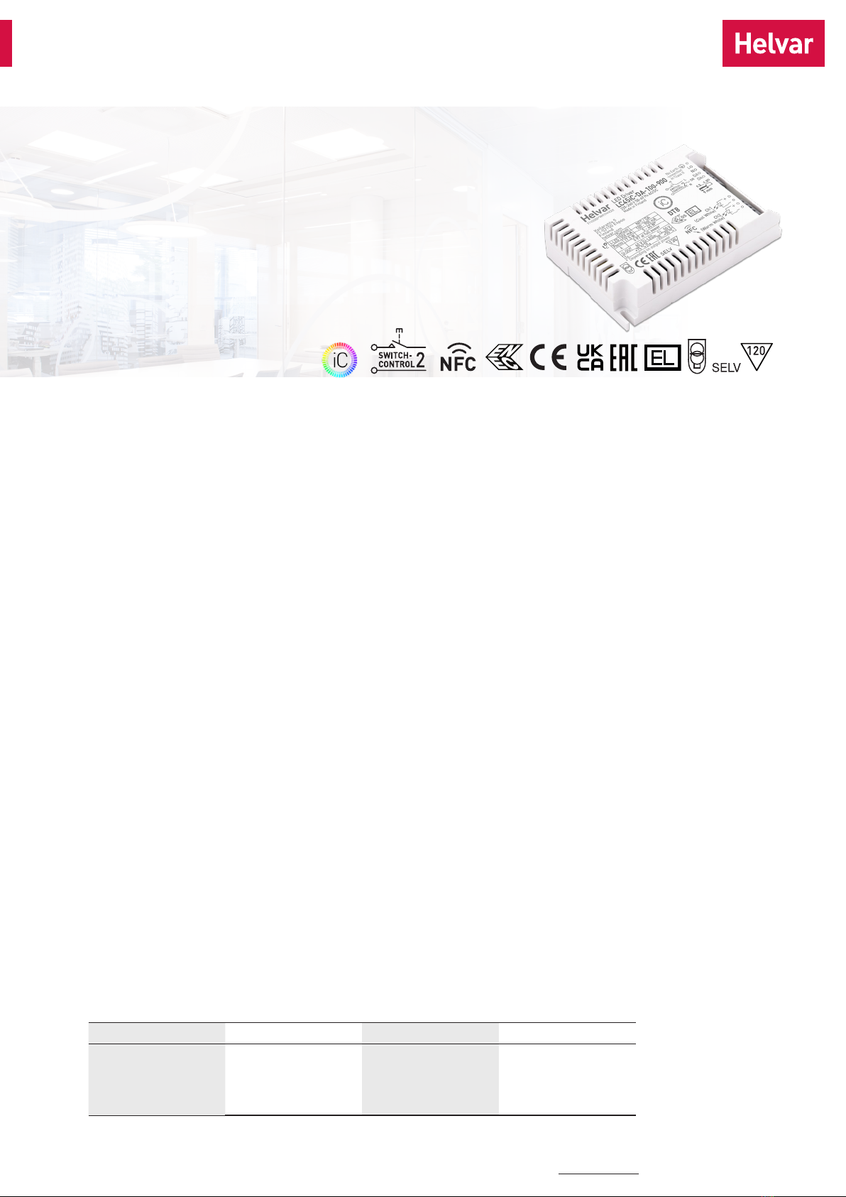
45 W Dimmable two channel intelligent Colour LED driver
• 2-channel tunable white for human centric lighting
• Wide dynamic range of colour temperatures on all dimming levels *
• Amplitude dimming for the highest quality light output, complying
with IEEE 1789 recommendation
• NFC technology for wireless programming
• Suitable for use in emergency lighting applications
• Suitable for Class I and Class II luminaires
• Optional strain relief for independent use outside of luminaire (LC-
SRB and LC-SRB-LOOP) and driving Class III luminaires
• Helvar Driver Configurator support
*) See pages 2-3 for details
45 W 220 – 240 V 0/ 50 – 60 Hz
Product code: 5765
*Current and power are divided into two channels according to the chosen CCT and module specifications. Total maximum power of the
two channels can’t exceed given PRated .
TUNABLE WHITE
23.06.2022 1/7T22 187 1A
LC45iC-DA-100-900

Helvar |Helvar Oy Ab, Keilaranta 5 FI-02150 Espoo, Finland. Data is subject to change without notice. www.helvar.com
Operating window
Driver performance
Operating Conditions and Characteristics
Absolute highest allowed tcpoint temperature 75 °C
Tc life (50 000 h) temperature 75 °C
Ambient temperature range* –25 °C ... +50 °C*
in independent use –25 °C ... +45 °C
Storage temperature range –40 °C ... +80 °C
Maximum relative humidity No condensation
Life time(90 % survival rate) 100 000 h, at tc = 65 °C
70 000 h, at tc = 70 °C
50 000 h, at tc = 75 °C
*) For other than independent use, higher taof the controlgear possible as long as highest allowed tcpoint temperature is not exceeded
*From 500 mA to 900 mA, full dimming range ( 2 % - 100 %) and wide CCT dynamic range available in the whole area.
From 100 mA to 500 mA, the absolute minimum dimming level is limited to 10 mA of total current. Dimming / CCT
control possible all the way down to that current, but the dynamic range may be limited. Each single channel can dim
down to 0.5 mA level.
0
10
20
30
40
50
60
0,00 0,10 0,20 0,30 0,40 0,50 0,60 0,70 0,80 0,90 1,00
Output voltage [V]
Output current [A]
ULED (max), V
ULED (min), V
50,0
56,0
62,0
68,0
74,0
80,0
86,0
92,0
0 5 10 15 20 25 30 35 40 45 50
Efficiency (%)
Total output power (W)
Typical efficiency
900 mA
350 mA
0,65
0,70
0,75
0,80
0,85
0,90
0,95
1,00
0 5 10 15 20 25 30 35 40 45 50
λ
Total output power (W)
Typical power factor
900 mA
350 mA
23.06.2022 2/7
LC45iC-DA-100-900
T22 187 1A

Helvar |Helvar Oy Ab, Keilaranta 5 FI-02150 Espoo, Finland. Data is subject to change without notice. www.helvar.com
Amplitude dimming technology
LC45iC-DA-100-900 LED driver implements amplitude dimming technology across whole dimming range. Amplitude dimming offers
the best available technology for dimming the light output in an accurate and flicker-free way to ensure high quality lighting in even
the most demanding situations such as camera recording applications. Amplitude dimming technology complies with IEEE 1789-2015
recommendations of current modulation to mitigate health risks to viewers.
0.1 % 100 %
0.1 %
100 %
LED current
Brightness
Amplitude
dimming
Dimming range per
single channel
Dimming range in
tunable white use Dimming technology
0.1 % –100 % 2 % - 100 % Amplitude (DC)
100% - 2 %
Constant dimming range across
the operating window
Cool white
Dynamic range
Warm white
1200 mA 500 mA
Dynamic range in colour temperature control
LC45iC-DA-100-900 LED driver is ready to be used out of the box.
Highest precision and color consistency in controlling combinations of different luminaire types is achieved by setting colour temperatures
and lumen outputs before use with Helvar driver configurator. The configured colour temperatures of the channels should match the ones
of the LED modules used. The factory default settings of cool and warm channels are 6500 K and 2700 K accordingly.
After setting up the colour temperatures, the lumen output values of full dimming level (100 %) should be configured for both channels. By
default, output currents are set to be equal in both channels.
10 mA
500 mA Total available dimming range
100 % - 10 %100 % - 2 %
Dimming range depends on the
set output current
100 mA
500 mA
Cool white
Warm white
Dynamic range
Dimming
outside the
operating
window
900 - 500 mA 500 - 100 mA
23.06.2022 3/7
LC45iC-DA-100-900
T22 187 1A
Helvar |Helvar Oy Ab, Keilaranta 5 FI-02150 Espoo, Finland. Data is subject to change without notice. www.helvar.com
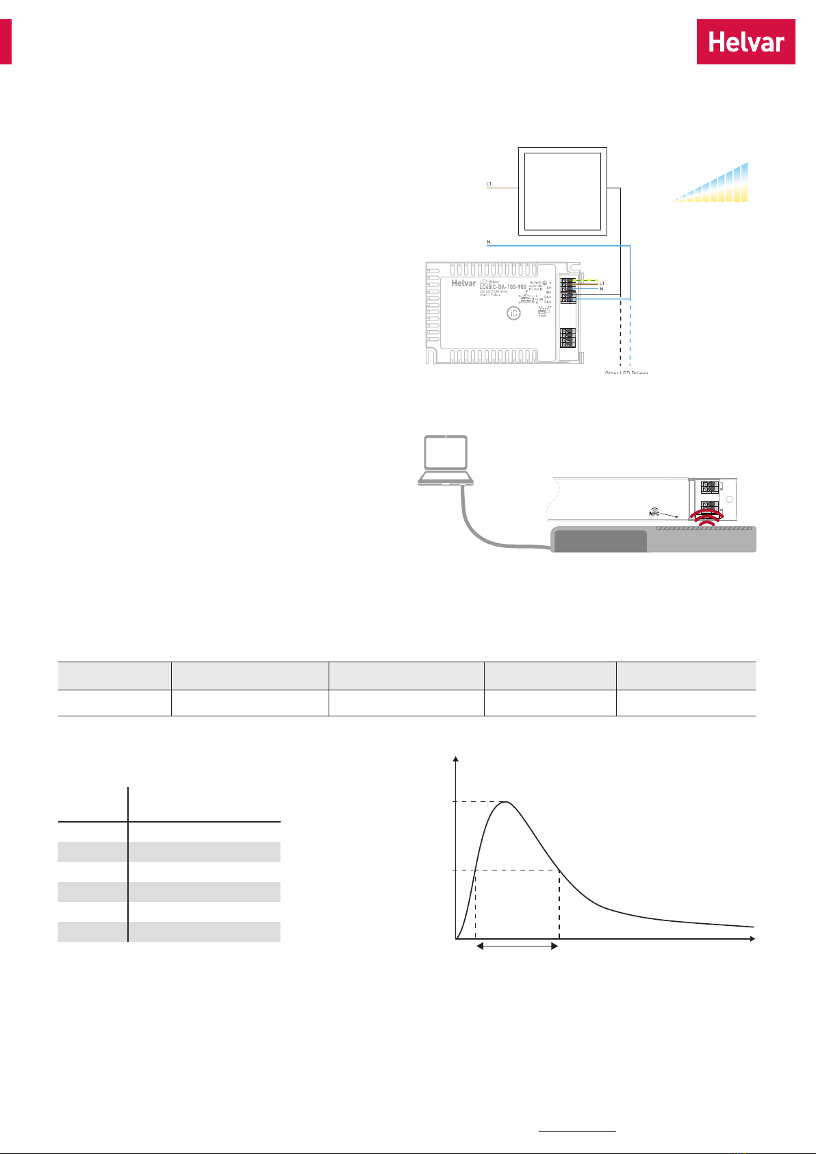
Switch-Control 2 with tunable white
Helvar iC drivers provide the simplest form of control in tunable
white with Helvar patented single switch Switch-Control 2
functionality. With single push button the user is able to control
both the light intensity and colour temperature to the desired level.
The system synchronises the light levels and CCTs every time the
colour temperature is adjusted to ensure pleasant user experience
and uncompromised lighting comfort. More information about the
functionality can be found in Switch-Control user guide at www.
helvar.com.
Wireless configuration
LC45iC-DA-100-900 LED driver is equipped with NFC wireless
technology for effortless configuration of the driver via Helvar
Driver Configurator Support. Helvar Driver Configurator enables
easy-to-use automatic configuration of the driver parameters via
NFC, without mains or DALI connection to the driver. The most
popular MD-SIG qualified NFC readers are supported giving flex-
ibility for the operator. For further information about the usage
with Helvar Driver Configurator, please see the user guide at
www.helvar.com
Feig NFC reader
Quantity of drivers per miniature circuit breaker 16 A Type C
CONVERSION TABLE FOR OTHER TYPES OF
MINIATURE CIRCUIT BREAKER
MCB
type
Relative quantity of
LED drivers
B 10 A 37 %
B 16 A 60 %
B 20 A 75 %
C 10 A 62 %
C 16 A 100 % (see table above)
C 20 A 125 %
CONTINOUS CURRENT
Total continous current of the drivers and installation environment must always be considered and taken into calculations when installing drivers behind
miniature circuit breaker. Example calculation of total drivers amount limited by continous current: n(Icont)= (16 A (Inom,Ta) / “nominal mains current with full
load”) x 0.76). This calculation is an example according to recommended precautions due to multiple adjacent circuit breakers (> 9 MCBs) and installa-
tion environment (Ta30 degrees); variables may vary according to the use case. Both inrush current and continous current calculations are based on
ABB S200 series circuit breakers. More specific information in ABB series S200 circuit breaker documentation.
NOTE! Type C MCB’s are strongly recommended to use with LED lighting. Please see more details in “MCB information” document in each driver product
page in “downloads & links” section.
I (A)
T (ms)
Ipeak
Δt
½ Ipeak
PE
0
I
Color temperature
and intensity control
Retractive Switch
(push to make)
Based on Icont Based on inrush current Ipeak Typ. peak inrush current Ipeak 1/2 value time, Δt Calculated energy, Ipeak
2Δt
51 pcs 58 pcs 29 A 153 µs 0.093 A2s
23.06.2022 4/7
LC45iC-DA-100-900
T22 187 1A
Helvar |Helvar Oy Ab, Keilaranta 5 FI-02150 Espoo, Finland. Data is subject to change without notice. www.helvar.com
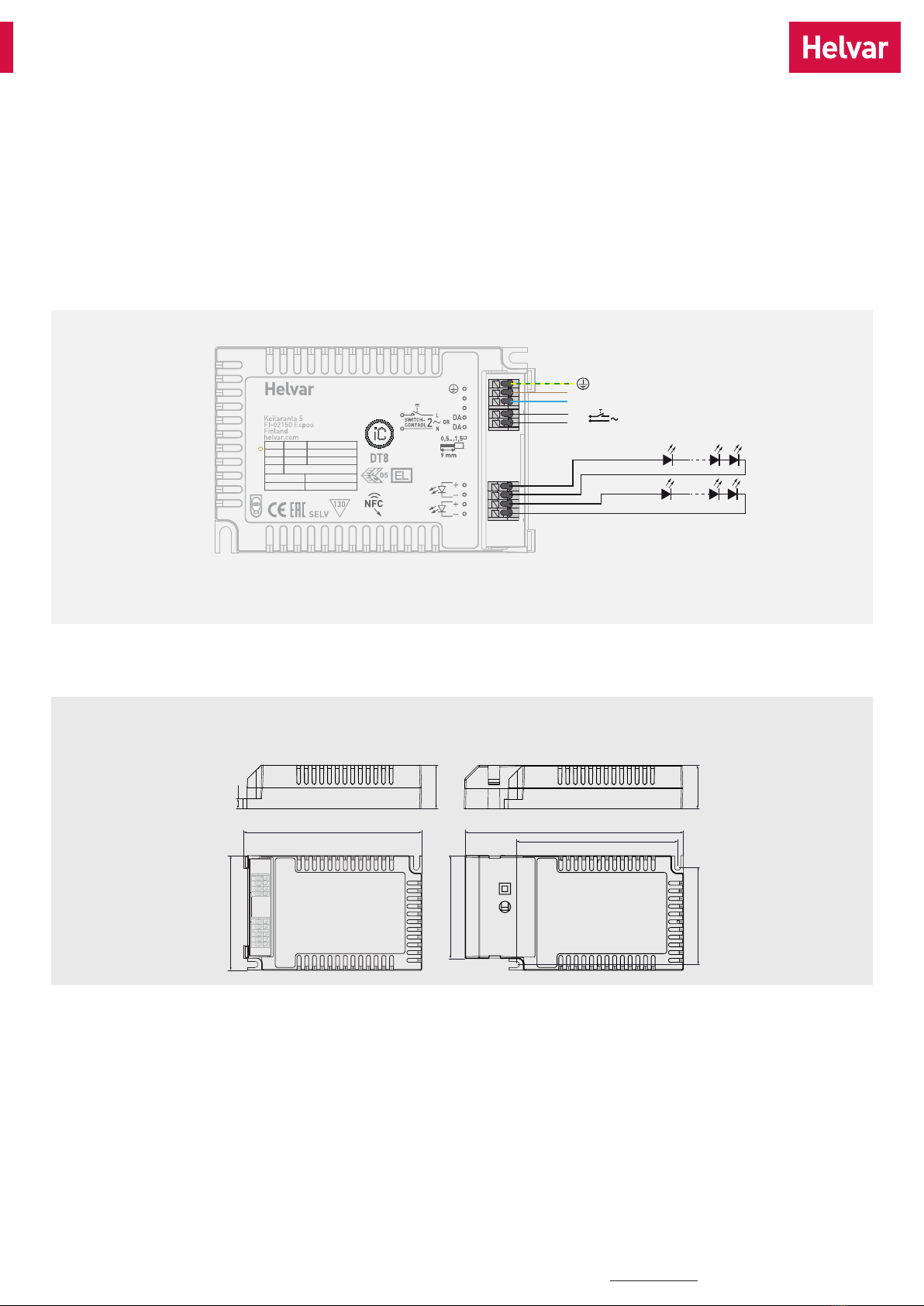
Connections
Dimensions (mm)
Connections and Mechanical Data
Wire size 0.5 mm2 –1.5 mm2
Wire type Solid core and fine-stranded
Wire insulation According to EN 60598
Maximum driver to LED wire length 1.5 m
Weight 193 g
IP rating IP20
CH1
(Cool white)
CH2
(Warm white)
L
N
DA
Switch-Control
tc
I-LED
350 mA 100 - 900 mA
5 - 45 W*
U-LED
dc
12...50 V
t
a
-25...+50 °C
U-OUT 60 V
t
c
+75 °C
λ
P
RATED
17.5 W
LED Driver
LC45iC-DA-100-900
220-240 V 50-60 Hz AC/DC
Made in Finland
Ch1
(Cool White)
Ch2
(Warm White)
L
N
5765000*WKYXXXXX
No Earth
connection
in Class II
NFC / DA
Default
0.97 at full power
* Depending on output power
30
With strain relief (LC1x70-SR)
122.9
79
150,5
71
111
67
30
6.5
Note:
• Earth connection to PE terminal is optional and not needed for the functionality of the driver. See page 4 for details.
• Not suitable for load side switching operation
• Label may differ if the unit is preset to fixed current
23.06.2022 5/7
LC45iC-DA-100-900
T22 187 1A

Helvar |Helvar Oy Ab, Keilaranta 5 FI-02150 Espoo, Finland. Data is subject to change without notice. www.helvar.com
LC45iC-DA-100-900 LED driver is suited for built-in usage in luminaires. With LC1x70-SR/LC-SRB/LC-SRB-LOOP strain relief, independent
use is possible too. In order to have safe and reliable LED driver operation, the LED luminaires will need to comply with the relevant
standards and regulations (e.g. IEC/EN 60598-1). The LED luminaire shall be designed to adequately protect the LED driver from dust,
moisture and pollution. The luminaire manufacturer is responsible for the correct choice and installation of the LED drivers according to
the application and product datasheets. Operating conditions of the LED drivers may never exceed the specifications as per the product
datasheet.
Installation & operation
Maximum ambient and tctemperature:
• For built-in components inside luminaires, the taambient
temperature range is a guideline given for the optimum
operating environment. However, integrator must always
ensure proper thermal management (i.e. mounting base of the
driver, air flow etc.) so that the tcpoint temperature does not
exceed the tcmaximum limit in any circumstance.
• Reliable operation and lifetime is only guaranteed if the
maximum tcpoint temperature is not exceeded under the
conditions of use.
LED driver earthing
• LC45iC-DA-100-900 is Class I LED driver suitable for Class I and
II luminaires, as well as driving Class III (SELV) luminaire parts
in independent installation with external strain relief.
• If used inside Class I luminaires, the earth cable is recommended
to be connected to improve the EMC performance of the driver,
but it is not mandatory. It is the responsibility of the integrator
to ensure that the assembled luminaire EMC performance
complies with the latest standards. Driver RFI measurement
data will be provided by request.
• If used inside Class II luminaires, the safety of the luminaire shall
be ensured through double/reinforced insulation of live parts.
LC45iC-DA-100-900 has double/reinforced insulation between
accessible and live parts, and is suitable for use in all Class II
luminaires. In this case the earth terminal of the driver must
be left unconnected and the luminaire terminal block shall not
have any protective earthing terminal.
• If used in independent installation with Class I/II/III luminaires,
the earth cable connection is optional. Please follow the
instructions provided in the strain relief datasheets.
Miniature Circuit Breakers (MCB)
• Type-C MCB’s with trip characteristics in according to EN 60898
are recommended.
• Please see more details in “MCB information” document in each
driver product page in “downloads & links” section.
Installation site
• The general preferred installation position of LED drivers for
independent use is to have the top cover facing upwards.
• Minimum recommended distances below:
• Suitable for installation upside down and in the corner, in this
case separate spacers must be used. For more information,
please consult Helvar.
Helvar Driver Configurator -support
LC45iC-DA-100-900 LED driver is supported by Helvar Driver
configurator software. The LC45iC-DA-100-900 driver supports
output current setting with software, the output current of the
driver can be programmed using Helvar Driver Configurator, as
well as OEM customer data and parameters for functions such as
CLO and Tunable White behavior. Programming the driver with
Helvar Driver Configurator can be done either wirelessly via NFC
or then via DALI bus.
23.06.2022 6/7
Information and conformity
T22 187 1A
Helvar |Helvar Oy Ab, Keilaranta 5 FI-02150 Espoo, Finland. Data is subject to change without notice. www.helvar.com
Conformity & standards
General and safety requirements EN 61347-1
Particular safety requirements for DC
or AC supplied electronic control gear
for LED modules
EN 61347-2-13
Additional safety requirements for AC or
DC supplied electronic controlgear for
emergency lighting
EN 61347-2-13,
Annex J
Thermal protection class EN 61347, C5e
Mains current harmonics EN 61000-3-2
Limits for voltage fluctuations and flicker EN 61000-3-3
Radio frequency interference EN 55015
Immunity standard EN 61547
Performance requirements EN 62384
Digital addressing lighting interface:
General requirements for DALI system
Requirements for DALI control gear
Requirements for control gear of LED
modules
Particular requirements for control gear
- Colour control (Dali Device Type 8)
EN 62386-101
EN 62386-102
EN 62386-207
EN 62386-209
Recommended Practices for Modulating
Current in High-Brightness LEDs for
Mitigating Health Risks to Viewers
IEEE 1789-2015
Compliant with relevant EU directives
RoHS/REACH compliant
ENEC and CE / UKCA marked
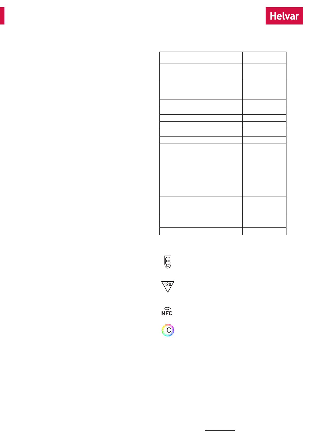
Label symbols
Safety isolating control gear with short circuit protection
(SELV control gear).
Thermally controlled control gear, incorporating means
of protection against overheating to prevent the case
temperature under any conditions of use from exceeding
120 °C.
Driver equipped with NFC wireless technology for
effortless configuration.
Helvar Intelligent Colour drivers providing DALI colour
control (tunable white) functionality.
Lamp failure functionality
No load
When open load is detected, driver will go to standby power
consumption and remains in automatic recovery mode. In automatic
recovery mode, the driver waits till load is returned and once that
happens, it returns to normal operation.
Short circuit
When short circuit is detected, driver goes to automatic recovery
mode and follows the same logic as described in the no load
condition.
Overload
When overload is detected, driver goes to standby mode and returns
through mains reset.
Underload
When undervoltage is detected, driver goes to standby mode and
returns through mains reset.
Switch-Control 2
Use of Switch-Control functionality
• Maximum numbers of LED drivers to be connected to one switch
is 60. Wire length is not restricted by the driver technology.
• Ensure that all components connected to Switch-Control
circuitry are mains rated.
• More information in Switch-Control User Guide at www.helvar.
com.
23.06.2022 7/7
Information and conformity
T22 187 1A
This manual suits for next models
1
Table of contents
Other HELVAR DC Drive manuals


Popular DC Drive manuals by other brands

Linear Technology
Linear Technology DC1187A quick start guide

Danfoss
Danfoss VLT FC 300 instruction manual

Siruba
Siruba 700LD manual

Overland Storage
Overland Storage NEO Series Remove & Replace / Add-On Instructions

Fagor
Fagor BCSD installation manual

Lenze
Lenze L-force EZAMBHXM00 Series Mounting instructions


