HELVAR LL1x150-CR-DA User manual

04.04.2022 1/6
T22 121 1E
LL1x150-CR-DA
Helvar |Helvar Oy Ab, Keilaranta 5 FI-02150 Espoo, Finland. Data is subject to change without notice. www.helvar.com
Functional Description
• Adjustable constant current output: 350 mA (default) to 700 mA
• Current setting programmable via DALI or with external resistors
• Filtered dimming for high-quality light in every application
• Latest technology Switch-Control 2 functionality for easy-to-use intensity control
• Adaptive LED overload protection, reduces output current if overvoltage is detected
• Full load recognition with automatic recovery, open and short circuit protection
• Multipurpose terminal Iset/NTC for current setting or overtemperature protection
• Constant Light Output (CLO), adjustable up to 100 000 h (default disabled)
Mains Characteristics
Voltage range 198 VAC – 264 VAC
Withstands max. 330 VAC (max. 1 hour)
DC range 176 VDC –280 VDC
starting voltage > 190 VDC
Mains current at full load 0.53 - 0.71 A
Frequency 0 / 50 Hz –60 Hz
Stand-by power consumption < 0.5 W
THD at full power < 10 %
Leakage current to earth < 0.5 mA
Tested surge protection 1 kV L-N, 2 kV L-GND (IEC 61000-4-5)
Tested fast transient protection 2 kV (IEC 61000-4-4)
Insulation between circuits & driver case
Mains circuit - Output Non-isolated
DALI circuit - Output Basic insulation
Mains circuit - DALI circuit Basic insulation
Mains, DALI and output - Driver case Basic insulation
Load Output
Output current (Iout) 350 mA (default) –700 mA
Accuracy ± 5 %
Ripple < 2 %* at ≤ 120 Hz *) Low frequency, LED load: Cree XM-L LEDs
PstLM < 0.02*
SVM < 0.01* *) At full power, measured with Cree XP-G LED modules.
Uout (max) (abnormal) 400 V
Outrush current 1100 mA*
*) When starting driver with short-circuited load or connecting load to running driver
Iout 350 mA 700 mA
Pout(max) 122.5 W 150 W
Uout 257 V –350 V 128 V – 214 V
PF (λ) at full load 0.97 0.98
Efficiency (η) at full load 96 % 95 %
150 W Dimmable DALI-2 LED driver
• DALI-2 certified LED driver, 1-100 % dimming range
• Very low flicker output complying with IEEE 1789 recommendations
• Suitable for flicker-free camera recording applications
• Very high efficiency up to 96 %
• Wide operating temperature range for various environments
• Suitable for DC use
• Long lifetime up to 100 000 h
• Driver protection Class I
• Suitable for closed luminaires where protection done with luminaire
construction (Class I or II)
• Helvar Driver Configurator support
150 W 220 – 240 V 0 / 50 – 60 Hz
Product code: 5790

04.04.2022 2/6
LL1x150-CR-DA
T22 121 1E
100
150
200
250
300
350
400
0,30 0,35 0,40 0,45 0,50 0,55 0,60 0,65 0,70 0,75 0,80
Output voltage [V]
Output current [A]
Helvar |Helvar Oy Ab, Keilaranta 5 FI-02150 Espoo, Finland. Data is subject to change without notice. www.helvar.com
Operating window and driver performane
Operating Conditions and Characteristics
Absolute highest allowed tcpoint temperature* 90 °C
tc life (60 000 h) lifetime temperature 80 °C
Ambient temperature range** –40 °C ... +50 °C
in independent use –40 °C ... +50 °C
Storage temperature range –40 °C ... +80 °C
Maximum relative humidity No condensation
Lifetime (90 % survival rate) 100 000 h, at tc= 70 °C
60 000 h, at tc= 80 °C
30 000 h, at tc= 90 °C
*) ENEC certified only up to tclife temperature
**) ENEC certified only down to ta-25 °C.
Below -30 °C DALI performance cannot be guaranteed.
For other than independent use, higher taof the controlgear possible as long as highest allowed tcpoint temperature is not exceeded.
Note: Dimming between 1 % - 100 % possible across
the whole operating window
91,0
92,0
93,0
94,0
95,0
96,0
97,0
80 90 100 110 120 130 140 150 160
Efficiency (%)
Total output power (W)
Typical efficiency
350 mA
700 mA
0,93
0,94
0,95
0,96
0,97
0,98
0,99
80 90 100 110 120 130 140 150 160
λ
Total output power (W)
Typical power factor
350 mA
700 mA
8
10
12
14
16
18
20
22
24
26
28
30 40 50 60 70 80 90 100 110 120 130 140 150 160
THD [%]
Load [W]
Current THD

04.04.2022 3/6
LL1x150-CR-DA
T22 121 1E
Helvar |Helvar Oy Ab, Keilaranta 5 FI-02150 Espoo, Finland. Data is subject to change without notice. www.helvar.com
Filtered dimming technology
Filtered dimming technology is created to achieve extremely high quality and flicker free light output even at the lowest dimming levels.
Light output is dimmed with amplitude dimming until the very lowest light levels (< 3%) and below that, stable light output is provided
with filtered high frequency signal. Dimming technology complies with IEEE 1789-2015 recommendations of current modulation to
mitigate health risks to viewers.
3 % 100 %
3 %
100 %
LED current
Brightness
Amplitude
dimming
1 %
3 %
3 %
1 %
Filtered
dimming
Dimming range Modulation frequency
100 % –3 % 0 Hz (DC)
3 % – 1 % > 2 kHz
Quantity of drivers per miniature circuit breaker 16 A Type C
Based on inrush current Ipeak Typ. peak inrush current Ipeak 1/2 value time, Δt Calculated energy, Ipeak
2Δt
24 pcs. 44 A 192 µs 0.2565 A2s
CONVERSION TABLE FOR OTHER TYPES OF
MINIATURE CIRCUIT BREAKER I (A)
T (ms)
Ipeak
Δt
½ Ipeak
MCB
type
Relative quantity of
LED drivers
B 10 A 37 %
B 16 A 60 %
B 20 A 75 %
C 10 A 62 %
C 16 A 100 % (see table above)
C 20 A 125 %
Total continous current of the drivers and installation environment must always be considered and taken into calculations when installing
drivers behind miniature circuit breaker. Example calculation of total drivers amount limited by continous current: n(Icont) = (16 A (Inom,Ta) /
“nominal mains current with full load”) x 0.76). This calculation is an example according to recommended precautions due to multiple
adjacent circuit breakers (> 9 MCBs) and installation environment (Ta30 degrees); variables may vary according to the use case. Both in-
rush current and continous current calculations are based on ABB S200 series circuit breakers. More specific information in ABB series
S200 circuit breaker documentation.
NOTE! Type C MCB’s are strongly recommended to use with LED lighting. Please see more details in “MCB information” document in each
driver product page in “downloads & links” section.
CONTINOUS CURRENT

04.04.2022 4/6
LL1x150-CR-DA
Helvar |Helvar Oy Ab, Keilaranta 5 FI-02150 Espoo, Finland. Data is subject to change without notice. www.helvar.com
Connections
Dimensions (mm)
Connections and Mechanical Data
Wire size 0.5 mm2 –1.5 mm2
Wire type Solid core and fine-stranded
Wire insulation According to EN 60598
Maximum driver to LED wire length 5 m
Weight 306 g
IP rating IP20
Resistor (Ω) 0 220 470 820 1k2 1k5 2k2 2k74 3k9 5k6 6k8 10k 18k 39k Open
Iout (mA) 700 675 650 625 600 575 550 525 500 475 450 425 400 375 350
Order code T70000 N/A T70471 T70821 N/A T70152 T70222 T72741 T70392 T70562 T70682 T70102 T70183 N/A N/A
T22 121 1E
L
N
DA
Switch-Control
R
350
21
30
4.5
350
360
Iset current setting resistor values, E48 series (Nominal Iout (±5 % tol.))
Output current can be set with the current setting resistor connected to the Iset terminal. Example current and resistor values across
the range can be found in the following table. More information about the current setting resistor is given on page 4.

04.04.2022 5/6Helvar |Helvar Oy Ab, Keilaranta 5 FI-02150 Espoo, Finland. Data is subject to change without notice. www.helvar.com
LL1x150-CR-DA LED driver is suited for built-in usage in luminaires. With LL1x2130-SR strain reliefs, independent use is possible too (see
the LL1x2130-SR datasheet for details). In order to have safe and reliable LED driver operation, the LED luminaires will need to comply
with the relevant standards and regulations (e.g. IEC/EN 60598-1). The LED luminaire shall be designed to adequately protect the LED
driver from dust, moisture and pollution. The luminaire manufacturer is responsible for the correct choice and installation of the LED
drivers according to the application and product datasheets. Operating conditions of the LED drivers may never exceed the specifications
as per the product datasheet.
Installation & operation
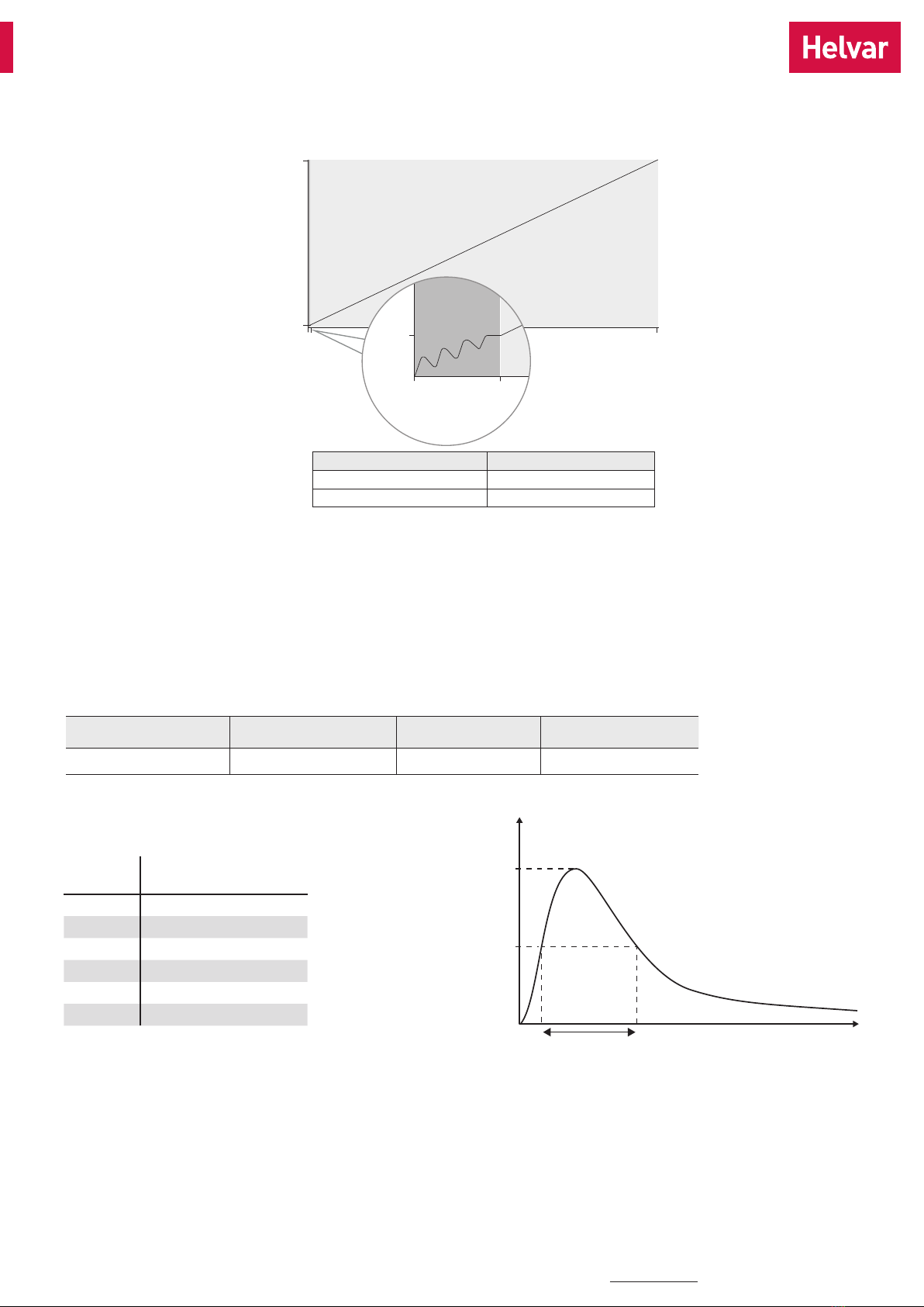
Maximum ambient and tctemperature
• For built-in components inside luminaires, the taambient
temperature range is a guideline given for the optimum
operating environment. However, integrator must always
ensure proper thermal management (i.e. mounting base of the
driver, air flow etc.) so that the tcpoint temperature does not
exceed the tcmaximum limit in any circumstance.
• Reliable operation and lifetime is only guaranteed if the
maximum tcpoint temperature is not exceeded under the
conditions of use.
Current setting resistor
LL1x150-CR-DA LED driver features a constant current output
adjustable via current setting resistor or software.
• An external resistor can be inserted in to the current setting
terminal, allowing the user to adjust the LED driver output current
• When no external resistor is connected, then the LED drivers will
operate at their default lowest current level
• A standard through-hole resistor can be used for the current
setting. To achieve the most accurate output current it is
recommended to select a quality low tolerance resistor. Minimum
diameter for resistor leg is 0.51mm.
• Always connect the current setting resistor only into the terminals
marked with Iset on the LED driver label.
• Specific Iset resistor/current values are presented in the table on
page 3.
Miniature Circuit Breakers (MCB)
• Type-C MCB’s with trip characteristics in according to EN 60898
are recommended.
• Please see more details in “MCB information” document in each
driver product page in “downloads & links” section.
Switch-Control 2
Before installation and for troubleshoot and guidance, refer to
Switch-Control User Guide at www.helvar.com.
Use of Switch-Control functionality
• Maximum numbers of LED drivers to be connected to one switch
is 60. Wire length is not restricted by the driver technology.
• Ensure that all components connected to Switch-Control
circuitry are mains rated.
• The X2 rated (1 μF) capacitor has to be installed between control
lines in case of unwanted behavior of lights. See details and
guidance from the user guide.
Helvar Driver Configurator -support
LL1x150-CR-DA LED driver is supported by Helvar Driver configurator
software. The LL1x150-CR-DA driver supports output current setting
with software, the output current of the driver can be programmed
using Helvar Driver Configurator, as well as parameters for functions
such as CLO. Also the operation of the multifunction Iset terminal
usage can be changed from current setting resistor (default) to NTC
overtemperature protection operation.
Lamp failure functionality
No load
When open load is detected, driver will go to standby. Automatic
recovery is on during the first 10 minutes. If open load is still detected
after the first 10 minutes, driver goes to standby mode and recovers
through mains reset.
Short circuit
When short circuit is detected, driver goes to standby mode and
returns through mains reset or DALI command.
Overload
When high overload is detected, driver goes to standby mode and
follows the same logic as described in the short circuit condition.
When low overload is detected, output current will be reduced to have
maximum rated output power.
Underload
When undervoltage is detected, driver goes to standby mode and
returns through mains reset.
NTC trigger
When NTC is enabled via Helvar Driver Configurator, driver follows
NTC feature behaviour. Default NTC trigger point is 8,2 kΩ, after
which the driver starts to decrease the output level.
Information and conformity
T22 121 1E

04.04.2022 6/6Helvar |Helvar Oy Ab, Keilaranta 5 FI-02150 Espoo, Finland. Data is subject to change without notice. www.helvar.com
Conformity & standards
General and safety requirements EN 61347-1: 2015
Particular safety requirements for DC
or AC supplied electronic control gear
for LED modules
EN 61347-2-13: 2014+
A1:2017
Additional safety requirements for AC
or DC supplied electronic controlgear
for emergency lighting
EN 61347-2-13: 2014,
Annex J
Thermal protection class EN 61347, C5e
Mains current harmonics EN 61000-3-2: 2014
Limits for voltage fluctuations and
flicker
EN 61000-3-3: 2013
Radio frequency interference EN 55015: 2013
Immunity standard EN 61547: 2009
Performance requirements EN 62384: 2006+
A1:2009
Digital addressing lighting interface:
General requirements for DALI system
Requirements for DALI control gear
Requirements for control gear of LED
modules (DALI Device Type 6)
EN 62386-101 (DALI-2)
EN 62386-102 (DALI-2)
EN 62386-207 (DALI-2)
Recommended Practices for
Modulating Current in High-Brightness
LEDs for Mitigating Health Risks to
Viewers
IEEE 1789-2015
Compliant with relevant EU directives
RoHS / REACH compliant
ENEC and CE / UKCA marked
Label symbols
Thermally controlled control gear, incorporating means
of protection against overheating to prevent the case
temperature under any conditions of use from exceeding
120 °C.
DALI-2 certified control gear.
Information and conformity
T22 121 1E
This manual suits for next models
1
Table of contents
Other HELVAR DC Drive manuals