Helvi PC EVO 66 User manual

MANUALE D’ISTRUZIONEMANUALE D’ISTRUZIONE
ITIT
3PH PLASMA CUTTING UNIT3PH PLASMA CUTTING UNIT
UNITÁ DI TAGLIO AL PLASMA 3PHUNITÁ DI TAGLIO AL PLASMA 3PH
UNITÉ DE COUPE PLASMA 3PHUNITÉ DE COUPE PLASMA 3PH
3PH PLASMASCHNEIDANLAGE3PH PLASMASCHNEIDANLAGE
UNIDAD DE CORTE DE PLASMA 3PHUNIDAD DE CORTE DE PLASMA 3PH
UNIDADE DE CORTE PLASMA 3PHUNIDADE DE CORTE PLASMA 3PH
INSTRUCTION MANUALINSTRUCTION MANUAL
MANUEL D’INSTRUCTIONSMANUEL D’INSTRUCTIONSFRFR
ENEN
PC EVO 66PC EVO 66
MANUAL DE INSTRUCCIONESMANUAL DE INSTRUCCIONES
ESES
BEDIENUNGSANLEITUNGBEDIENUNGSANLEITUNG
MANUAL DE INSTRUÇÕESMANUAL DE INSTRUÇÕESPP
DD

II
INDEX
FOREWORD EN-1
SAFETY EN-1
WARNINGS EN-1
PERSONAL PROTECTION EN-2
LIGHT RADIATIONS EN-2
WORKING AREA EN-2
ELECTRIC SYSTEM EN-4
FIRE PREVENTION EN-4
PROTECTION GAS EN-5
NOISE EN-5
FIRST AID EN-5
ELECTROMAGNETIC COMPATIBILITY EN-5
GENERAL INFORMATION EN-6
TECHNICAL INFORMATION EN-6
INSTALLATION EN-6
LOCATION EN-6
MAIN SUPPLY VOLTAGE REQUIREMENTS EN-6
SAFETY INSTRUCTIONS EN-6
CONNECTION TO GROUND CABLE EN-7
TORCH CONNECTION EN-7
TORCH CONSUMABLE PARTS MOUNTING EN-7
COMPRESSED AIR EN-7
PURGE EN-7
CONNECTION OF THE MACHINE TO
THE CNC EN-8
ARC VOLTAGE SIGNAL EN-8
FUNCTIONS EN-9
CUTTING OPERATION EN-10
PRELIMINARIES EN-10
CUTTING EN-11
MAINTENANCE EN-13
OPERATING FAULTS EN-14
TROUBLESHOOTING EN-14
TORCH CONSUMABLES A÷B
INDICE
PREMESSA IT-1
SICUREZZA IT-1
AVVERTENZE IT-1
PROTEZIONE PERSONALE IT-2
RADIAZIONI LUMINOSE IT-2
AREA OPERATIVA IT-2
IMPIANTO ELETTRICO IT-4
PREVENZIONE D’ INCENDIO IT-4
GAS DI PROTEZIONE IT-5
RUMORE IT-5
PRONTO SOCCORSO IT-5
EMC IT-5
GENERALITA’ IT-6
DATI TECNICI IT-6
INSTALLAZIONE IT-6
COLLOCAZIONE IT-6
REQUISITI DELLA TENSIONE DI RETE IT-6
ISTRUZIONI PER LA SICUREZZA IT-7
COLLEGAMENTO DEL CAVO DI MASSA IT-7
COLLEGAMENTO DELLA TORCIA IT-7
MONTAGGIO CONSUMABILI TORCIA IT-7
ALLACCIAMENTO ARIA COMPRESSA IT-7
SPURGO IT-7
COLLEGAMENTO A SISTEMI DI
TAGLIO AUTOMATICI IT-8
SEGNALE DI TENSIONE DELL’ARCO IT-8
FUNZIONI IT-9
OPERAZIONI DI TAGLIO IT-10
PRELIMINARI IT-10
TAGLIO IT-11
MANUTENZIONE IT-13
DIFETTI DI TAGLIO IT-14
RICERCA GUASTI IT-14
CONSUMABILI TORCIA A÷B
CONTENU
AVANT-PROPOS FR-1
SÉCURITÉ FR-1
AVERTISSEMENT FR-1
PROTECTION PERSONNELLE FR-2
RADIATIONS LUMINEUSES FR-2
CIRCUIT ÉLECTRIQUE FR-4
PRÉVENTION D’INCENDIE FR-4
GAZ DE PROTECTION FR-5
BRUIT FR-5
PREMIERS SECOURS FR-5
EMC FR-5
GÉNÉRALITÉS FR-6
DONNÉES TECHNIQUES FR-6
INSTALLATION FR-6
MISE EN PLACE FR-6
CONDITIONS REQUISES POUR LA TENSION
DU RESEAU FR-6
INSTRUCTIONS POUR LA SÉCURITÉ FR-7
BRANCHEMENT DU CABLE DE MASSE FR-7
BRANCHEMENT DU CHALUMEAU POUR LE
COUPE PLASMA FR-7
MONTAGE DES PIÈCES CONSOMMABLES
DE CHALUMEAU FR-7
BRANCHEMENT DE L’AIR COMPRIMÉ FR-8
PURGE FR-8
CONNEXION DE LUNITÉ A SYSTÈMES DE
COUPE AUTOMATIQUE FR-8
SIGNAL DE TENSION D’ARC FR-8
DISPOSITIFS DE CONTROLE, SIGNALISATION
ET SECURITÉ FR-9
OPÉRATIONS DE COUPE FR-10
PRÈLIMINAIRE FR-10
COUPE FR-11
ENTRETIEN FR-13
DISFONCTIONNEMENTS HABITUELS FR-14
DÉPANNAGE FR-14
CONSOMMABLES DE CHALUMEAU A÷B
INHALT
VORWORT D-1
SICHERHEIT D-1
HINWEISE D-1
PERSÖNLICHE SCHUTZAUSRÜSTUNG D-2
LICHTSTRAHLEN D-2
ARBEITSBEREICH D-2
ELEKTRISCHE ANLAGE D-4
BRANDVERHÜTUNG D-4
SCHUTZGAS D-5
GERÄUSCHENTWICKLUNG D-5
ERSTE HILFE D-5
EMV (ELEKTROMAGNETISCHE
VERTRÄGLICHKEITS-RICHTLINIE) D-5

III
ALLGEMEINE INFORMATIONEN D-6
TECHNISCHE DATEN D-6
INSTALLATION D-6
PLATZIERUNG D-6
NETZSPANNUNG – ALLGEMEINE
BEDINGUNGEN D-6
SICHERHEITSVORSCHRIFTEN D-7
ANSCHLUSS DES MASSEKABELS D-7
ANSCHLUSS DES SCHNEIDBRENNERS D-7
MONTAGE DER D-7
BRENNERVERSCHLEISSTEILE D-7
DRUCKLUFTVERSORGUNG D-8
ENTLEERUNG D-8
CNC SCHNITTSTELLE D-8
SIGNAL LICHTBOGENSPANNUNG D-8
FUNKTIONEN D-9
SCHNEIDVORGANG D-10
VORBEREITENDE MASSNAHMEN D-10
SCHNEIDEN D-11
INSTANDHALTUNG D-13
BEDIENUNGSFEHLER D-14
HINWEISE ZUR FEHLER BEHEBUNG D-14
BRENNERVERSCHLEISSTEILE A÷B
CONTENIDO
PREÁMBULO ES-1
SEGURIDAD ES-1
ADVERTENCIAS ES-1
PROTECCIÓN PERSONAL ES-2
RADIACIONES LUMINOSAS ES-2
AREA OPERATIVA ES-2
INSTALACIÓN ELÉCTRICA ES-4
PREVENCIÓN DE INCENDIOS ES-4
GAS DE PROTECCIÓN ES-5
RUIDO ES-5
PRIMEROS AUXILIOS ES-5
EMC ES-5
DATOS GENERALES ES-6
DATOS TÉCNICOS ES-6
INSTALACIÓN ES-6
COLOCACIÓN ES-6
REQUISITOS DE LA TENSIÓN DE
LA RED ELÉCTRICA ES-6
INSTRUCCIONES PARA LA SEGURIDAD ES-7
CONEXION AL CABLE DE TIERRA ES-7
CONEXION DE LA ANTORCHA DE CORTE ES-7
MONTAJE DE LOS CONSUMIBLES DE LA
ANTORCHA ES-7
CONEXION DEL AIRE COMPRIMIDO ES-8
SISTEMA DE PURGA ES-8
CONEXIÓN A SISTEMAS AUTOMÁTICOS DE
CORTE ES-8
SEÑAL DE TENSIÓN DE ARCO ES-8
FUNCIONES ES-9
OPERACIONES DE CORTE ES-10
PRELIMINARES ES-10
CORTE ES-11
MANTENIMIENTO ES-13
ERRORES DE CORTE MAS COMUNES ES-14
BUSQUEDA DE AVERIAS ES-14
CONSUMIBLES DE LA ANTORCHA A÷B
ÍNDICE
INTRODUÇÃO P-1
SEGURANÇA P-1
ADVERTÊNCIAS P-1
PROTECÇÃO PESSOAL P-2
RADIAÇÕES LUMINOSOS P-2
ÁREA OPERACIONAL P-2
CIRCUITO ELÉCTRICO P-4
PREVENÇÃO DE INCÊNDIO P-4
GÁS DE PROTECÇÃO P-5
RUÍDOS P-5
PRIMEIROS SOCORROS P-5
EMC (COMPATIBILIDADE ELECTROMAGNÉTICA) P-5
INFORMAÇÕES GERAIS P-6
DADOS TÉCNICOS P-6
INSTALAÇÃO P-6
COLOCAÇÃO P-6
REQUISITOS DA TENSÃO DE REDE P-6
INSTRUÇÕES PARA SEGURANÇA P-7
CONEXÃO DO CABO DE TERRA P-7
CONEXÃO DA TOCHA P-7
MONTAGEM DOS CONSUMÍVEIS DA TOCHA P-7
CONEXÃO DE AR COMPRIMIDO P-8
PURGA P-8
CONEXÃO AOS SISTEMAS DE CORTES
AUTOMÁTICOS P-8
SINAL DE TENSÃO DO ARCO P-8
FUNÇÕES P-9
OPERAÇÕES DE CORTE P-10
PRELIMINARES P-10
CORTE P-11
MANUTENÇÃO P-13
DEFEITOS DE CORTE P-14
RESOLUÇÃO DE PROBLEMAS P-14
CONSUMÍVEIS DA TOCHA A÷B
TORCH CONSUMABLES
H.70 A
HM.70 B
EN-1
Thank you for purchasing our products. When
assembled and used correctly, our welding gene-
rators are reliable and long-lasting and will help
increase the productivity of your business with
minimum maintenance costs.
All these appliances were designed, manufactured
and tested entirely in Italy, in full accordance with
the European Directives of Low Voltage (2006/95/
EC) and EMC (2004/108/EC), by applying norms
EN 60974.1 (safety rules for electric material, Part 1:
source of welding current) and EN 60974-10 (EMC
Electromagnetic Compatibility) and are identified as
Class A products.
Class A appliances were not designed for use in
domestic environments in which power is supplied
through a public low-voltage grid; it is therefore po-
tentially difficult to ensure the electromagnetic com-
patibility of Class A appliances in such environments,
due to radiated and conduced disturbances.
These professional electric appliances must therefore
only be used in industrial environments, connected
to private power distribution cabins.
These generators are therefore not subject to the
European/International EN/IEC regulation 61000-
3-12 which defines the maximum levels of harmonic
distortion induced in the public grid of low-voltage
power distribution.
The installer or the user (if necessary, contact your
power distributor) is responsible for ensuring that
these appliances can be connected to a public low-
voltage grid.
Warning: the manufacturer refuses all re-
sponsibility in the event of unauthorized mo-
difications performed on its products.
FOREWORD
These power generators must only be used for the
cutting procedures described in this manual; they
must never be employed to recharge batteries, for the
thawing of water pipes, for the heating of buildings
by means of added resistances etc.
Compliance to RoHS Directive: We hereby declare
that this range of generators 3Ph described in this
manual is in accordance with RoHS EU Regulations
2011/65/UE of 8 June 2011 regarding the restriction
of the use of certain substances harmful for human
health present in Electric and Electronic Equipment
(EEE).
This symbol, applied to the welding generator
or to its packaging, indicates that, at the end
of its useful life, the product must not be tre-
ated as ordinary waste, but must be collected
separately from other waste and in accordan-
ce with European Directive 2012/19/UE of 4
July 2012 regarding the disposal of waste
electrical and electronic equipment (WEEE).
These must be collected separately and di-
sposed of in an environmentally compatible
way.
As owner of an EEE product (Electrical Electronic
Equipment), you are responsible for contacting your
area dealers for information on authorized collectors.
Applying the above mentioned European Directive
improves the environment and our own health.
Warning: Welding, cutting and similar tech-
niques may be dangerous operations for
the worker and for anyone near the wor-
king area. Please carefully read the SAFE-
TY chapter below in order to reduce risks.
SAFETY
WARNINGS
This manual contains instructions for the proper in-
stallation of the Electric Electronic Equipment (EEE)
you have just purchased.
The owner of an EEE must make sure that this
document is read and understood by welding tech-
nicians and their assistants and by maintenance
technicians.
Warning: Even when the ON/OFF switch of
the EEE is at “O”, voltage from the power grid
is still present within the generator and in the
power cable. Prior to any internal inspection,
make sure the appliance has been discon-
nected from the power source (this means ta-
king a series of steps in order to separate the
appliance from the power source and to keep
it free from voltage).
Electrical electronic appliances may never be used
without their panels and covers, as this may be
dangerous for the workers involved. Using the ap-
pliances without these protections may cause serious
damage to the appliances themselves.
These generators may be supplied by an electricity
generator, which must absolutely be equipped with
a diesel engine with a power higher than the power
required by the generator (see technical data table)
and output voltage of 400Vac +/- 10% - 3Ph –
50/60Hz.
SMALTIMENTO DI APPARECCHI DA ROTTAMARE DA PARTE DI PRIVATI NELL’UNIONE EUROPEA
Questo simbolo che appare sul prodotto o sulla confezione indica che il prodotto non deve essere smaltito assieme agli altri rifiuti domesti-
ci. Gli utenti devono provvedere allo smaltimento delle apparecchiature da rottamare portandole al luogo di raccolta indicato per il riciclag-
gio delle apparecchiature elettriche ed elettroniche. La raccolta ed il riciclaggio separati delle apparecchiature da rottamare in fase di smal-
timento favoriscono la conservazione delle risorse naturali e garantiscono che tali apparecchiature vengano rottamate nel rispetto dell’am-
biente e della tutela della salute. Per ulteriori informazioni sui punti di raccolta delle apparecchiature da rottamare, contattare il proprio comu-
ne di residenza, il servizio di smaltimento dei rifiuti locale o il negozio presso il quale è stato acquistato il prodotto.
DISPOSAL OF WASTE EQUIPMENT BY USERS IN PRIVATE HOUSEHOLDS IN THE EUROPEAN UNION
This symbol on the product or on its packaging indicates that this product must not be disposed of with your other household waste. Instead,
it is yr responsibility to dispose of yr waste equipment by handing it over to a designated collection point for the recycling of waste electri-
cal and electronic equipment. The separate collection and recycling of yr waste equipment at the time of disposal will help to conserve natu-
ral resources and ensure that it is recycled in a manner that protects human health and the environment. For more information about where
you can drop off yr waste equipment for recycling, please contact yr local city office, yr household waste disposal service or the shop where
you purchased the product.
EVACUATION DES ÉQUIPEMENTS USAGÉS PAR LES UTILISATEURS DANS LES FOYERS PRIVÉS AU
SEIN DE L’UNION EUROPÉENNE
La présence de ce symbole sur le produit ou sur son emballage indique que vous ne pouvez pas vous débarrasser de ce produit de la même
façon que vos déchets courants. Au contraire, vous êtes responsable de l’évacuation de vos équipements usagés et à cet effet, vous êtes tenu
de les remettre à un point de collecte agréé pour le recyclage des équipements électriques et électroniques usagés. Le tri, l’évacuation et le
recyclage séparés de vos équipements usagés permettent de préserver les ressources naturelles et de s’assurer que ces équipements sont recy-
clés dans le respect de la santé humaine et de l’environnement. Pour plus d’informations sur les lieux de collecte des équipements usagés,
veuillez contacter votre mairie, votre service de traitement des déchets ménagers ou le magasin où vous avez acheté le produit.
ENTSORGUNG VON ELEKTROGERÄTEN DURCH BENUTZER IN PRIVATEN HAUSHALTEN IN DER EU
Dieses Symbol auf dem Produkt oder dessen Verpackung gibt an, dass das Produkt nicht zusammen mit dem Restmüll entsorgt werden darf.
Es obliegt daher Ihrer Verantwortung, das Gerät an einer entsprechenden Stelle für die Entsorgung oder Wiederverwertung von
Elektrogeräten aller Art abzugeben (z.B. ein Wertstoffhof). Die separate Sammlung und das Recyceln Ihrer alten Elektrogeräte zum
Zeitpunkt ihrer Entsorgung trägt zum Schutz der Umwelt bei und gewährleistet, dass sie auf eine Art und Weise recycelt werden, die keine
Gefährdung für die Gesundheit des Menschen und der Umwelt darstellt. Weitere Informationen darüber, wo Sie alte Elektrogeräte zum
Recyceln abgeben können, erhalten Sie bei den örtlichen Behörden, Wertstoffhöfen oder dort, wo Sie das Gerät erworben haben.
ELIMINACIÓN DE RESIDUOS DE APARATOS ELÉCTRICOS Y ELECTRÓNICOS POR PARTE DE
USUARIOS DOMÉSTICOS EN LA UNIÓN EUROPEA
Este símbolo en el producto o en el embalaje indica que no se puede desechar el producto junto con los residuos domésticos. Por el contra-
rio, si debe eliminar este tipo de residuo, es responsabilidad de usuario entregarlo en un punto de recolección designado de reciclado de apa-
ratos electrónicos y eléctricos. El reciclaje y la recolección por separado de estos residuos en el momento de la eliminación ayudarán a pre-
servar recursos naturales y a garantizar que el reciclaje proteja la salud y el medio ambiente. Si desea información adicional sobre los luga-
res donde puede dejar estos residuos para su reciclado, póngase en contacto con las autoridades locales de su ciudad, con el servicio de
gestión de residuos domésticos o con la tienda donde adquirió el producto.
DESCARTE DE EQUIPAMENTOS POR USUÁRIOS EM RESIDÊNCIAS DA UNIÃO EUROPEIA
Este símbolo no produto ou na embalagem indica que o produto não pode ser descartado junto com o lixo doméstico. No entanto, é sua respon-
sabilidade levar os equipamentos a serem descartados a um ponto de colecta designado para a reciclagem de equipamentos eletro-eletrônicos.
A colecta separada e a reciclagem dos equipamentos no momento do descarte ajudam na conservação dos recursos naturais e garantem que os
equipamentos serão reciclados de forma a proteger a saúde das pessoas e o meio ambiente. Para obter mais informações sobre onde descartar
equipamentos para reciclagem, entre em contacto com o escritório local de sua cidade, o serviço de limpeza pública de seu bairro ou a loja em
que adquiriu o produto.

EN-2
PERSONAL PROTECTION
• Workers and their assistants must protect
themselves by wearing closed, non-flamma-
ble protection coveralls, without pockets or
rolled sleeves or legs. Any residue of oil or
grease must be cleaned from the garments
before wearing them. Only wear CE marked
garments suitable for arc welding and cutting
(Fig. 1):
1. Gloves;
2. Apron or jacket made of crust leather;
3. Gaiters to protect the shoes and the bottoms
of the trousers;
4. Protection shoes with steel toes and rubber soles;
5. Mask (please consult the paragraph on light
radiations);
6. Crust leather sleeves to protect the arms.
• Users must wear fireproof helmet or mask,
designed in such a manner as to offer protec-
tion to the neck and face (including the sides)
against the light of the electric arc (glare from
the visible light and infrared and ultraviolet
radiations). The helmet or the mask must be
equipped with a protector whose degree of
opacity will depend on the welding or cutting
procedure and on the value of the electric arc
current, according to the values contained in
Table 1 (EN 169).
Figure 1
Caution: Make sure all protection gar-
ments are in good conditions and replace
them regularly in order to ensure perfect
personal protection.
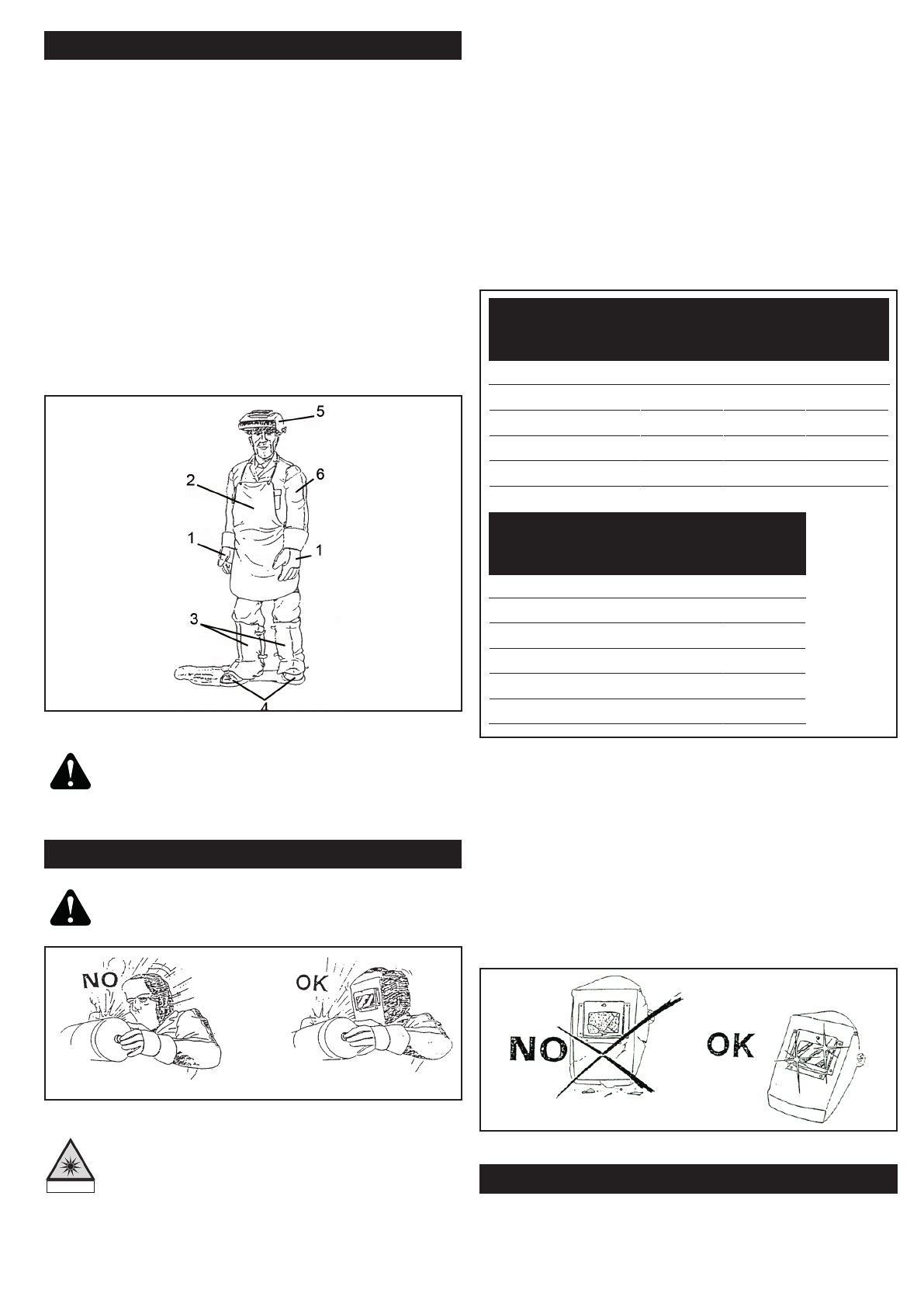
LIGHT RADIATIONS
Warning: Never stare at an electric arc wi-
thout suitable eye protection (Fig. 2).
Figure 2
According to the requirements in 2006/25/
EC Directive and EN 12198 Standard, the
equipment is a category 2. It makes com-
pulsory the adoption of Personal Protective
Equipment (PPE) having filter with a pro-
tection degree up to a maximum of 15, as
required by EN169 Standard.
• The colored filter (inactinic filter) must be kept
clean at all times. Should it break or dete-
riorate (Fig. 3), replace it with a new filter,
with the same degree of opacity. The colored
filter must be protected against impact and
welding or cutting projections by means of a
transparent glass positioned on the anterior
part of the mask. This transparent glass must
be replaced whenever visibility is reduced du-
ring welding.
DIN Taglio
Plasma Elettrodi
Rivestiti
Elettrodi
Carbonio
Arc/Air TIG
9 20 - 39A 5 - 19A
10 40 - 79A 125 - 174A 20 - 39A
11 50 - 149A 80 - 174A 175 - 224A 40 - 99A
12 150 - 249A 175 - 299A 225 - 274A 100 - 174A
13 250 - 400A 300 - 499 275 - 349A 175 - 249A
14 500A 350 - 449A 250 - 400A
DIN MIG per
Leghe
Leggere
MIG per
Pezzi d’Ac-
ciaio MAG
9
10 80 - 99A 80 - 99A 40 - 79A
11 100 - 174A 100 - 174A 80 - 124A
12 175 - 249A 175 - 299A 125 - 274A
13 250 - 349A 300 - 499A 275 - 349A
14 350 - 499A 500 - 550A 350 - 449A
Table 1
Figure 3
WORKING AREA
Welding or cutting operations must be carried out
in a sufficiently ventilated place, isolated from other
working areas. If this is not possible, anyone near
the person operating the welding machine and
their assistants must be protected by curtains and
Optical Radiation Emission
Category 2
(EN 12198)

EN-3
• Prior to any welding or cutting operation, cle-
ar the working area from all chlorine solvents,
which are normally used to clean or degrea-
se the working material. The fumes of these
solvents, when submitted to the radiations of
an electric arc, even from afar, may, in some
cases, transform into toxic gases. Make sure
all the pieces which are to be welded or cut
are absolutely dry.
Warning: When the welding operator is in
a closed space, the use of chlorine solvents
is absolutely forbidden in the presence of
electric arcs.
• During the grinding, brushing and hamme-
ring operations involving the welded pieces,
always wear protection goggles with transpa-
rent lens to prevent projected chips and any
other foreign particles from hurting your eyes
(Fig. 5).
transparent opaque screens, self-extinguishable and
in accordance with regulation in force (the color of
the screen will depend on the welding process and
on the value of the currents used), anti-UV goggles
and, if necessary, masks with suitable protection
filter (Fig. 4).
Figure 4
Figure 6
Figure 5
Unhealthy or dangerous gases or fumes must be
collected (as they are produced) as close and effi-
ciently as possible to the source of emission, in such
a manner that the concentration of pollutants does
not exceed the permitted limits (Fig. 6). In addition,
all welding operations must be carried out on metal
surfaces devoid of rust and paint, to avoid the
formation of hazardous fumes.
Any symptom of discomfort or pain in the eyes, nose
or throat may be caused by inadequate ventilation;
if this is the case, immediately interrupt work and
ventilate the area.
Do not weld or cut metals or painted metals contai-
ning zinc, lead, cadmium or beryllium, unless the
operator and the persons nearby are using breathing
apparatuses or wearing helmets with oxygen cylinder.
Should welding or cutting operations be carried out
in conditions different from the usual working condi-
tions, with an increased risk of electric shock (reduced
or damp working area), additional precautions must
be taken, such as:
• Using power generators marked “S”;
• Placing the power generator out of the wor-
king area;
• Reinforcing personal protection devices,
ground insulation and insulation between the
piece to be welded and the operator (Fig. 7).
Figure 7
Workers and their assistances must never allow
any parts of their bodies to come into contact with
metallic materials at high temperatures or which are
moving (Fig. 8).
EN-4
Figure 8
Using the arc welding and cutting equipment requires
strict respect for safety conditions regarding electric
currents. Make sure that no metallic parts accessible
to the operators may come into direct or indirect
contact with a phase conductor or with the neutral
of the power grid.
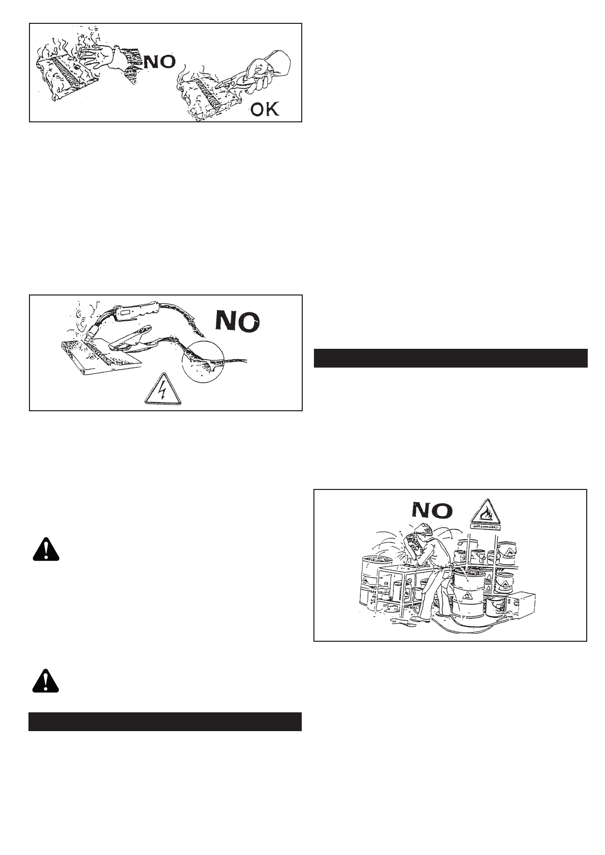
All electrode holders and torches used must be in
good conditions. Do not coil the cables around your
body and never point the torchs to other people
(Fig. 9).
Figure 9
Make sure that no power cables from other ap-
pliances, control lines or phone cables are near the
generators.
Any other electric equipment in the welding or cutting
area must be in conformity with the corresponding
EMC regulation.
Caution: Access to the the working area
and near the welding/cutting operation
generators is forbidden to anyone wearing
pacemakers or other such electric devices.
At least once every 6 months make sure that all
electric appliances and accessories are well insulated.
Contact your supplier for more information on the
maintenance and repair of such equipment.
Warning: Never touch the welding cable or
the electrode and the piece which is being
welded at the same time.
ELECTRIC SYSTEM
Any intervention on electrical and electronic
equipment must be entrusted to qualified technicians
capable of performing such operations.
Prior to connecting your appliance to the power grid,
make sure that the counter, the overload and short-
circuit protection devices, the sockets, the plugs and
the electric system as a whole are compatible with
the maximum power of the appliance and its voltage
(please check the information on the plate) and in
conformity with the norms and regulations in force.
The ground single-phase or three-phase connection
(yellow/green cable) must be protected by a medium
or high-intensity differential-residual current device
(sensitivity between 1 and 30 mA).
If the cable is connected, the earth cable (when
present) must not be interrupted by the protection
device against electric shock. The switch, if present,
must be at “O”; the power cable, if not supplied,
must be of the harmonized type.
Ground all metal parts near the operator, using
cables that are thicker or as thick as the welding
cables.
The protection class of the appliance is IP22S, which
means it prevents:
- manual contact with internal parts in high tempe-
rature, which are moving or live;
- the introduction of solid bodies with more than 12
mm of diameter;
- protection against rain with maximum inclination
of 15°.
FIRE PREVENTION
The working area must be in conformity with safety
regulations. This means that fire extinguishers must
be installed, compatible with the type of fire which
may happen.
The ceiling, the floor and the doors must be non-
flammable. All combustible material must be moved
away from the workplace (Fig. 10). If this is not
possible, cover it with a fireproof cover.
Figure 10
Before you start welding or cutting, ventilate all areas
that are potentially flammable.
Do not use the equipment in places with significant
concentrations of dust, flammable gas or combusti-
ble liquid vapor.
The generator must be placed on solid, smooth floor,
and should never lean against walls.
Do not weld or cut containers filled with gasoline,
lubricant or other flammable substances.

EN-5
Under normal work conditions, the noise emitted by
a welding/cutting generator does not exceed 80 dBA;
should it be necessary to emit noise above 85 dBA,
the worker involved must be equipped with suitable
protections, such as helmet and ear plugs, and be
informed by suitable signaling.
FIRST AID
Each country specifies the minimum personal pro-
tection equipment that employers must provide their
first aid team with, for immediate help in the event of
electric shock, suffocation, burns of different types,
eye burns etc.
Beware of electric shock and electric burns:
the workplace may be dangerous; do not
attempt to help the patient if the power
source is still active. Cut off the appliance
from the power source and remove all po-
wer cables from the victim using a piece of
dry wood or any other insulating material.
ELECTROMAGNETIC COMPATIBILITY
Before installing your welder, carry out an inspection
of the surrounding area, observing the following
guidelines:
• Make sure that there are no other power sup-
ply cables, control lines, telephone leads or
other equipment near the unit.
• Make sure that there are no radio receivers,
television appliances, computers or other
control systems near the unit.
• People with pace-maker or hearing-prosthe-
sis should keep far from the power source.
! In particular cases special protection
measures may be required.
Interference can be reduced by following these sug-
gestions:
• If there is interference in the power source
line, an E.M.T. filter can be mounted between
the power supply and the power source;
• The output cables of the power source should
be not too uch long, kept together and con-
nected to ground;
• After the maintenance all the panels of the po-
wer source must be securely fastened in place.
Do not weld or cut near ventilation ducts, gas ducts
or any other installation which could accelerate the
spreading of a fire.
After concluding the welding or cutting operation,
always make sure that no incandescent or burning
material has been left in the area.
Make sure the earth connection is good; a defective
ground connection may result in an electric arc which
can become the cause of a fire.
PROTECTION GAS
Strictly follow all instructions of use and handling
provided by the gas supplier. In particular: the areas
of storage and use must be open and ventilated,
sufficiently away from the working area and from
sources of heat (< 50°C). Fix the cylinders, protect
them from impact and from any technical accident.
Make sure the cylinder and the pressure gauge corre-
spond to the gas required for the welding operation.
Never lubricate the cylinder taps and do not forget
to remove all gas from the same before connecting
the pressure gauge.
The protection gases must be dispensed at the
pressures recommended for the different welding/
cutting procedures.
Periodically inspect the ducts and rubber tubes to
make sure they are properly sealed. Never use
a source of flame/fire to detect gas leaks; use a
suitable detector or brush the suspected area with
soapy water.
Warning: Improper use of the gas, in par-
ticular in small spaces (cargo holds, tanks,
reservoirs, silos etc), will expose the user to
the following risks:
1. Suffocation or intoxication with gas and gassy
mixtures containing less than 20% of carbon
dioxide (these gases replace oxygen in the
air);
2. Fire and explosion with gassy mixtures con-
taining hydrogen (hydrogen is light and flam-
mable; it accumulates beneath ceilings or in
nooks, resulting in risk of fire and explosion).
NOISE
The safety prescriptions regarding workers’ pro-
tection against the risks derived from exposure to
noise are treated by European Directive 2003/10/
CE of 6 February 2003, which describes the need
to adopt measures to promote safety, hygiene and
good health in the workplace.
The noise emitted by the welding and cutting gene-
rators depends on the intensity of the welding/cutting
current, on the procedure used (MIG, pulsed MIG,
TIG etc), on the work environment (size of the area,
reverberation of the walls etc).

EN-6
PLASMA ARC AND BASIC PRINCIPLES
FOR THE PERFORMANCE OF PLASMA
CUTTING
• Plasma is a gas that is heated to an extremely
high temperature and ionised so that it beco-
mes a conductor of electricity.
• This cutting procedure utilises the plasma to
transfer the electric arc to the metal workpiece,
which is melted by the heatand then separated.
• The torch uses compressed air from a single
source, for both the plasma and cooling and
protective gas.
• The start of the cycle is determided by an arc,
called the pilot arc, which is struck between
the mobile electrode(negative polarity) and
the torch nozzle (positive polarity) due to the
short circuit between these two elements.
• When the torch is brought into direct contact
with the workpiece to be cut (connetcted to
the positive polarity of the power source) the
pilot arc is transfered between the electrode
and the workpiece itself thus striking a pla-
sma arc, also called cutting arc.
• The duration of the pilot arc is set in the fat-
cory at 3 seconds; if the transfer has not been
made within this time, the cycle is automati-
cally stopped except for the cooling air which
is kept on.
TECHNICAL INFORMATION
The data in the following table may differ
from the values on the data plates on the
rear panel of the generators.
The data may also vary according to the
torch that is gonna be used with the gene-
rator.
GENERAL INFORMATION
INSTALLATION
Be sure to locate the welder according
to the following guidelines.
• In areas, free from moisture and dust;
• Ambient temperature between 0° to 40°C;
• In areas, free from oil, steam and corrosive
gases;
• In areas, not subjected to abnormal vibration
or shock;
• In areas, not exposed to direct sunlight or rain;
• Make sure that obstacles do not prevent the
cooling air flow out of front and rear ope-
nings of the machine.
• Arrange an open space of at least 5m around
the machine.
• In the case the machine has to be moved,
always disconnect the plug from the outlet
and gather the cables and pipes so as not to
damage them.
Since the inhalation of welding fumes
can be harmful, ensure that the welding
area is effectively ventilated.
MAIN SUPPLY VOLTAGE REQUIREMENTS
Before you make any electrical connection,
check that supply voltage and frequency avai-
lable at site are those stated in the ratings la-
bel of your generator.
The main supply voltage should be within ±10% of
the rated main supply voltage. Too low a voltage
may cause poor welding performance. Too high a
supply voltage will cause components to overheat
and possibly fail. The welder Power Source must be:
• Correctly installed, if necessary, by a qualified
electrician;
• Correctly grounded (electrically) in accordan-
ce with local regulations;
• Connected to the correct size electric circuit.
LOCATION
PC 66 EVO
EN-7
In case the supply cable is not fitted with a plug,
connect a standardized plug (3P+T) to the supply
cable (in some models the supply cable is supplied
with plug).
To connect the plug to the supply cable, follow these
instructions:
• the brown (phase) wire must be connected to
the terminal identified by the letter L1
• the blue or grey wire must be connected to
the terminal identified by the letter L2
• the black or grey wire must be connected to
the terminal identified by the letter L3
• the yellow/green (ground) wire must be con-
nected to the terminal identified by the letter
PE or by the symbol .
In any case, the connection of the yellow/green wire
to the PE terminal must be done in order that in
the event of tearing of the power supply cable from
the plug, the yellow/green wire should be the last
one to be disconnected.
The outlet should be protected by the proper
protection fuses or automatic switches.
Notes:
• Periodically inspect supply cable for any
cracks or exposed wires. If it is not in good
conditions, have it repaired by a Service Cen-
tre.
• Do not pull violently the input power cable to
disconnect it from supply.
• Do not squash the supply cable with other ma-
chines, it could be damaged and cause electric
shock.
• Keep the supply cable away from heat sorces,
oils, solvents or sharp edges.
• In case you are using an extension cord, try to
keep it well straight and avoid its heating up.
SAFETY INSTRUCTIONS
For your safety, before connecting the power source
to the line, closely follow these instructions:
• An adequate switch must be inserted before
the mains outlet; this switch must be equip-
ped with time-delay fuses;
• The connection with ground must be made
with a plug compatible with the above men-
tioned socket;
• When working in a confined space, the power
source must be kept outside the welding area
and the ground cable should be fixed to the
workpiece. Never work in a damp or wet area,
in these conditions.
• Do not use damaged input or welding cables
• The welding torch should never be pointed at
the operator’s or at other persons’ body;
• The power source must never be operated
without its panels; this could cause serious
injury to the operator and could damage the
equipment.
CONNECTION TO GROUND CABLE
Connect the plug to the socket and the work cable
clamp to the piece to be cut or to the metallic
workbench. Take following precautions:
• Verify that there is a good electrical contact
particularly if insulated or oxidated coated
sheets are cut.
• Make ground connections as close as possi-
ble to the cutting area. The use of the metallic
structures which are not part of the workpie-
ce, such as the return cable of the cutting
current, may endanger the safety system and
give poor cutting results.
• Do not make a ground connection on the pie-
ce which has to be removed.
TORCH CONNECTION
Ensure unit is off and unpluged from the power
receptacle.
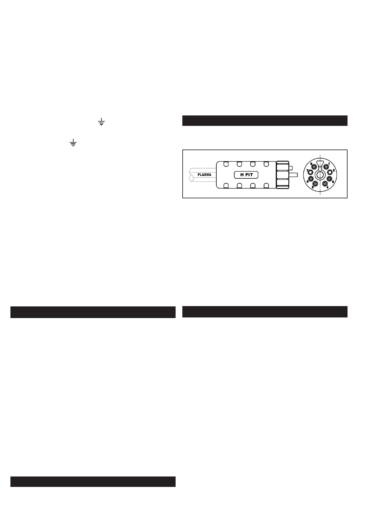
Figure 11
Supplied torch, manual or automatic, has a quick
connection system called “H Fit” . Correctly align the
“H Fit” pins and connect it to the connector on the
front panel of the unit by handscrewing the plastic
ring.
WARNING!: Before starting the cutting
operations verify that the parts are pro-
perly assembled by inspecting the head of
the torch as described on paragraph “Torch
Maintenance”.
TORCH CONSUMABLE PARTS MOUNTING
Position the torch with the outside protection nozzle
facing upward to prevent these parts from falling out
when the nozzle is removed.
WARNING: Wait the torch has completely
cooled before replacing torch parts to avoid
any damage to the torch head.
To change the torch consumable parts use the
following procedure:
1. Unscrew and remove the shield cup from the
Torch Head Assembly.
2. Remove the tip, gas distributor, and electrode.
3. Install the electrode, gas distributor, and tip.
Choose the correct consumable parts, refer
to the paragraph “Torch consumable parts
selection”.
4. Hand tighten the shield cup until it is seated
on the torch head. If resistance is felt when
installing the cup, check the threads before
proceeding.
5. if necessary, install also the spacer.
EN-8
CONNECTION OF THE MACHINE TO THE CNC
The machine is ready for the connection to
the robotic machines.
• Ensure unit is off and unpluged from the po-
wer receptacle.
• The machine is provided of a 14-pin male
connector located on the back panel. Con-
nect the power contact of the robotic machine
to a 14-pin female connector suitable for the
connector mounted on the machine by fol-
lowing the here shown diagram.
• Connect the male connector to the machine.
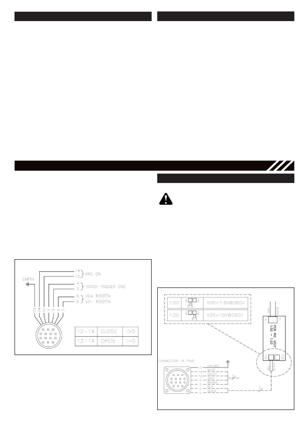
Figure 12
Figure 13
ARC VOLTAGE SIGNAL
AUTION! ELECTRIC SHOCK CAN KILL
Following operation should be carried out
by trained personnel who are aware of the
risks caused by the high voltage.
Carefully read the instructions and speci-
fications of the CNC machine before pro-
ceeding.
By default, the reduction of the output voltage is
equal to 1:50. In the case that the cutting table to be
connected requires a different voltage, it is possible
to set a 1:20 reduction. FIG. 13
• Remove the connector on PS1: 50.
• Install the connector into PS1: 20
COMPRESSED AIR
A source of clean, dry air or nitrogen must be
supplied to your plasma cutting unit.
The supply pressure must be between 6 and 8 bar.
The flow rate is approximately 240 l/min for H.70
torch.
Failure to observe these precautions could
result in excessive operating temperatures
or damage to the torch.
An air regulator is included with the unit with
optimum pressure setting set to 5.5 Bar.
Note: the regulator should never be
set above 8 bar.
Note: LEDs on the front panel of the unit
will show if the input air pressure is not
correctly adjusted.
PURGE
Oil in the air is a severe problem and must be
avoided.
The unit is also equipped with an air filter which
captures water and oil vapor.
The vapor collected can be drained out turning the
drain knob located on the air filter.
The knob has two positions:
1. Open
The drain knob should not be left in this
position during the cutting operations.
2. Closed
EN-9
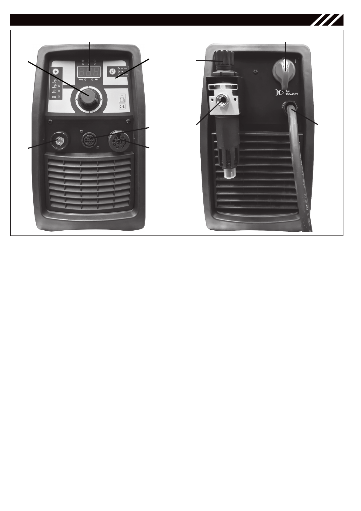
FUNCTIONS
1. ON/FF Switch
In the ON position the machine is ready for normal
operation. All system control circuits are activated.
OFF position deactivates control circuits.
2. Output Current Knob (2)
Adjusts the cutting current supplied by the machine
according to application (thickness of material/
speed).
3. Display
It views the set cutting current when unit is on, during
pilot arc time views the pilot arc current and during
cutting views the cutting current.
It views the adjusted air pressure (bar) by pushing
the air drain key (B).
4. Control Panel
5. Air Regulator
It adjusts the input air pressure - pull outwards to
unlock. Note: push torch air purge key before acting
on the air regulator to get the air pressure displayed.
6. Earth cable connection (6)
7. Torch connection
8. Power cable
9. 14-Pin Male Connector
10. Compressed Air Connector
Figure 14
2
3
4
7
9
6
1
8
5
10

EN-10
CUTTING OPERATION
PRELIMINARIES
WARNING
unplug the unit from the power supply
before assemble or disassemble piled
parts, single parts, parts of the torch,
torch assemblies or cables.
• Check and follow instructions as foreseen in
the paragraphs “Safety and Installation” of
the present instructions manual.
A. Operation Mode Selection Key
•Non-continuous pilot arc. Cuts or pierces
metal plate. Standard setting for normal
cutting.
•Automatic pilot arc. Cuts expanded metal or
grate.
•Gouge. Gouges metal plate.
•Cutting with CNC
B. Torch Air Purge Key
It allows to remove any condensation that may have
accumulated in the torch and leads while the system
was shut down, to get the pressure set thru the air
regulator (5) viewed on the display and to select and
set the secondary parameters.
C. Air Pressure Indication LEDs
• Green LED “OK” ON = correct air pressure
Figure 15
• Red LED “Increase” ON = too low air pres-
sure
• Red LED “Decrease” ON = too high air pres-
sure
D. Cutting Current LED
when on it means that the display is viewing the
adjusted or the effective cutting current.
E. BAR LED
when on it means that the display is viewing the
adjusted pressure.
F. Green LED
It is on when power is applied to the unit. It blinks
by overvoltage, low voltage o missing of one phase.
G. Yellow LED
It is on by overtemperature.
H. Red LED
It is on when pilot arc or cutting arc is started.
PARTS OF THE TORCH
• Check the torch for proper assembly (refer
to Section called Torch Consumable Parts
Mounting).
• Install proper torch parts for the desired ap-
plication (refer to Section called Torch Consu-
mable Parts Selection).
INPUT POWER
• Check the power source for proper input vol-
tage.
• Plug unit in and close main disconnect switch
A
B CED HGF
EN-11
INITIAL SETUP
• Once unit is powered on, the display will show
“set” for a few seconds. In this time press the
left Selection key (A) to view the adjustable
parameters.
• Use the central knob (2) and the right selec-
tion key (B) to adjust the parameter:
- Pre-air safety.
Off = Arc starts immediately
On = Pre-air before the arc starts
On CNC cutting this safety can not be acti-
vated (off).
• Use the right selection key to confirm the pa-
rameter adjustment and return to the pre-
vious menù.
• To reset the parameters press and hold the
right selection key (B).
• Use the left selection key to exit.
CUTTING
CUTTING WITH A HAND TORCH
• Select the non-continuous pilot arc mode with
the selection key (A) in the control panel.
• The torch can be comfortably held in one
hand or steadied with two hands. Choose the
technique that feels most comfortable and
allows good control and movement. Position
the index finger or thumb to press the control
switch on the torch handle.
• For edge starts, hold the torch perpendicular
to the workpiece with the front of the tip on
the edge of the workpiece at the point where
the cut is to start - Fig. 16.
Figure 16
to supply primary power to the system.
GROUND CABLE
• Check for a solid ground cable connection to
the workpiece.
AUTOMATIC PURGE SYSTEM
• Place the ON/OFF switch to the ON position.
Activate the torch button to initiate 3s gas
purge (pre-flow) to remove any condensation
that may have accumulated in the torch and
leads while the system was shut down. When
the gas purge is complete, pilot arc will be
initiated. To cool torch handle or to further
remove condensation in the torch and leads
push the torch gas purge button (B) on the
front panel of the unit.
WARNING
Do not initiate pilot arc during adjustment.
CHECKING AIR QUALITY
• To check air quality, deactivate the torch (post-
flow) and place filter lens in front of the torch.
Any oil or moisture in the air will be visible
on the lens. DO NOT initiate pilot arc while
checking air quality.
OPERATION MODE SELECTION
• Select the desired operation mode with the
selection key (A) in the control panel.
AIR PRESSURE REGULATION
• Adjust the air pressure by pushing the air purge
button (B) and by acting on the air regulator (5).
• Adjust the correct air pressure for each ope-
ration mode.
Torch 6m H.70
Manaul cutting 3,5-4,5bar
Grid cutting 3,5-4,5bar
Gouging 2,5-4,0bar
CNC 3,5-4,5bar
For different torch length consider the following
pressure increases :
Torch Length H.70
10/12m +0bar
20m +0,4bar
30m +0,7bar
• The display shows the adjusted air pressure in
bars. If air pressure is correctly adjusted the
LED “OK” is on. If the LEDs “Increase” or “De-
crease” are on, adjust again the air pressure
until these get off and LED “OK” lights on.
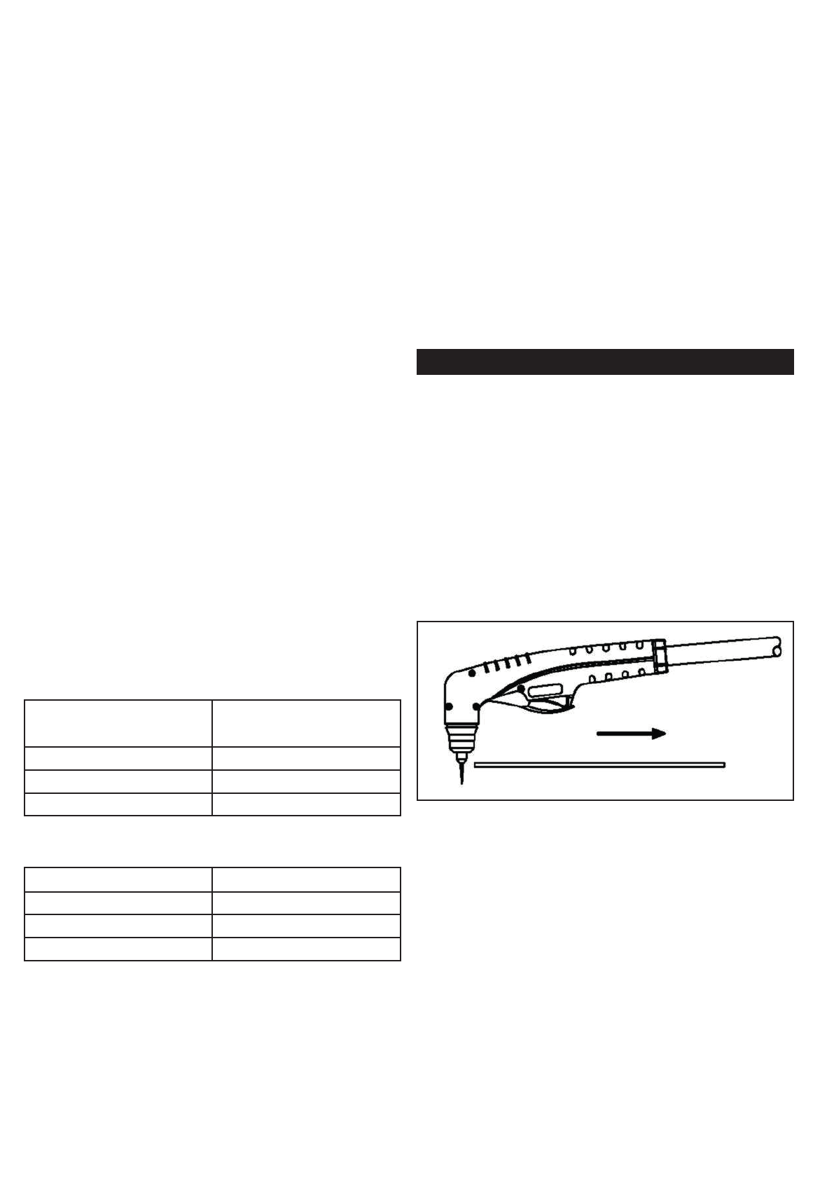
CUTTING CURRENT REGULATION
• Adjust the cutting current by acting on the ou-
tput current knob (2).
• With the torch in starting position, press the
control switch. After an initial gas purge (pre-
air), the pilot arc will come on and remain on
for 3 seconds until the cutting arc starts.
• Once on, the main arc remains on as long
as the control switch is held down, unless the
torch is withdrawn from the work or torch
motion is too slow. Keep moving while cut-
ting. Cut at a steady speed without pausing.
Maintain the cutting speed so that the arc lag
is about 30° behind the travel direction. Fig.
17. If the cutting arc is interrupted, and the
torch trigger is still pressed, the pilot arc co-
mes back on automatically for 3 seconds.
• To shut off the torch simply release the control
switch. When the switch is released a post-
flow will occur. If the torch trigger is pressed
during the post-flow, the pilot arc will restart.

EN-12
Figure 17
• Hold the torch at a 45° angle with the
workpiece. Press the trigger to obtain a pilot
arc. Transfer the arc to the workpiece.
• Pull the torch back by keeping a 45° angle
with the workpiece and a certain distance
between the torch tip and the molten metal to
avoid consumable life reduction or damage
to the torch.
Changing the torch’s angle change the di-
mensions of the gouge.
• The gouge profile may vary in accordance with:
1. speed of the torch over the workpiece
2. the torch-to-work standoff distance
3. the angle of the torch to the workpiece
4. the adjusted current output.
• To increase width:
- Increase the standoff and/or the current.
- Decrease the speed and/or the angle.
• To decrease width:
- Increase the speed and/or the angle.
- Decrease the standoff and/or the current
• To increase depth:
- Decrease the speed and/or standoff.
- Increase the current and/or the angle.
• To decrease depth:
- Decrease the current and/or the angle.
- Increase the speed and/or standoff.
CUTTING WITH CNC
• Select the CNC mode with the selection key
(A) in the control panel.
• Follow indications at paragraph “Connection
of the machine to a CNC”
• Since the equipment with mechanized torch
can be used with different cutting tables, for the
operations in such configuration it is necessary
to consult the manufacturer’s instructions.
WARNING
Disconnect primary power at the source
and wait that the torch has cooled before
disassembling the torch or torch leads.
Frequently review the Important Safety
Precautions at the front of this Manual. Be
sure the operator is equipped with proper
gloves, clothing, eye and ear protection.
Make sure no part of the operator’s body
comes into contact with the work piece
while the torch is activated.
CAUTION
Sparks from the cutting process can cause
damage to coated, painted, and other sur-
faces such as glass, plastic and metal.
NOTE
Handle torch leads with care and protect
them from damage.
Figure 19
PIERCING WITH A HAND TORCH
Note: Recommended maximum piercing
capacity depends on the torch and on the
cutting current of the cutting unit. Refer to
the torch specification sheet provided with
the cuttig unit. If necessary to make a cut
on a metal sheet with a tickness more than
the maximum piercing capacity without
an edge start, make a hole ø 6mm at least
using an electric drill to start cutting.
• When piercing with a hand torch, tip the torch
slightly.
Figure 18
• Complete the pierce off the cutting line and
then continue the cut onto the line. Hold the
torch perpendicular to the workpiece after the
cut is complete. Fig.19
• Clean spatter and scale from the shield cup
and the tip as soon as possible.
GRATES CUTTING
• Select the automatic pilot arc mode with the
selection key (A) in the control panel.
GOUGE
• Select the gouge mode with the selection key
(A) in the control panel.
• Hold the torch with torch tip within 1.5 mm
from the workpiece.

EN-13
MAINTENANCE
Maintenance can only be carried out on the unit if the
person in charge of this operation has the necessary
technical knowledge and the correct tools. If this is
not the case, contact your nearest service centre.
CAUTION!
Never access inside the machine (panel re-
moval) or touch the torch (disassemblage)
without having disconnected power plug.
Any inspection performed under voltage
inside the machine or inside the torch may
cause severe electric shocks caused by di-
rect contact with parts under voltage.
UNIT
Keep the cutting or gouging area and the area
around the machine clean and free of combustible
materials. No debris should be allowed to collect ,
this could obstruct air flow to the machine.
Inspect the unit every 3-4 months (depending on
how often the unit is used) and use compressed air
to remove any dust deposits.
CAUTION!
Only use dry compressed air for cleaning.
Do not point the jet of air at the electronic
circuits.
TORCH
Periodically, according to its use or to cutting faults
verify wear of the parts connected to plasma arc:
Shield Cup:
Unscrew manually from head of the torch. Clean
throughly abd replace if damaged (burns, distortions
or cracks). Verify integrity of superior metal sector
(actuator torch safety).
Tip:
Check wear of plasma arc hole and of inner and
outer surfaces. If the hole is widened compared to
its original width or if it is damaged, replace tip. If
surfaces are particularly oxidated clean them with
extra fine abrasive paper.
Air Distributor:
Verify the are no burns or cracks or that airflow holes
are not obstructed. If damaged, replace immediately.
Electrode:
Replace electrode when crater settling on emitting
surface is about 2mm.
WARNING!
• Before making any operation to the torch let
it cool at least all along the “postgas” period.
• Except for particular cases it is advisable to
replace electrode and tip AT THE SAME TIME.
• Respect assembly order of torch parts (reser-
ved compared to disassemblage).
• Be carefull that distributing is assembled pro-
perly.
• Reassemble shield cup screwing tightly and
manually.
• Never assemble shield cup without having
assembled electrode distributing ring and tip
beforehand.
• Timely and appropriate control procedures
on torch parts are essential for safety and
functionality of the cutting system.
TORCH BODY, HANDLE AND CABLE
• These parts usually need no particular main-
tenance with the exception of a periodic in-
spection and an accurate cleaning to be
made WITHOUT THE USE OF SOLVENTS.
• In case of damages to the insulation such as
breaks, cracks and burns or even a loosening
of electric coonductors, the torch CANNOT
BE USED FURTHER SINCE SAFETY CONDI-
TIONS HAVE NOT BEEN RESPECTED.
• IN THIS CASE, REPAIRING (EXTRAORDINA-
RY MAINTENANCE) CANNOT BE MADE ON
SITE BUT NEEDS TO BE DELEGATED TO A
SERVICE CENTER TO MAKE SPECIAL REST
TRIALS AFTER REPAIRING HAS BEEN EXECU-
TED.
In order to keep the torch and the cable efficient it
is necessary to follow these precautions:
• DO NOT touch torch and cable with warm
or hot parts.
• DO NOT strain the cable.
• DO NOT move the cable on sharp edges or
abrasive surfaces.
• gather the cable in regular coils if it is too
long.
• DO NOT step on the cable.
COMPRESSED AIR FILTER
The unit is also equipped with an air filter which
captures water and oil vapor.
Water contained in the glass can be drained through
a knob located on the bottom of the air filter. See
Purge Section.

EN-14
OPERATING FAULTS
During cutting operations performance faults may
arise which are not caused by plant malfunctioning
but by other operational faults such as:
• Insufficient penetration:
too high cutting speed;
torch is too tilted;
piece is too thick;
cutting current too low;
torch parts are worn out;
non-genuine Manufacturer’s parts;
• Interruption of the cutting arc:
cutting speed too slow;
excessive distance between torch and workpiece;
AC line too low - reduce output current;
torch parts are worn out;
non-genuine Manufacturer’s parts;
work cable is disconnected;
• Excessive scoria settlement:
too low cutting speed (bottom dross);
too high cutting speed (top dross);
excessive distance between torch and workpie-
ce;
cutting current too low;
torch parts are worn out;
non-genuine Manufacturer’s parts;
• Tilted cutting (not perpendicular):
torch position not correct;
asymmetric wear of nozzle hole and/or
wrong; assemblage of the torch parts;
• Excessive wear of nozzle and electrodes:
air pressure too low;
exceeding system capability (material too
thick);
contaminated air (humidity-oil);
excessive pilot arc arc ignitions in the air;
Improperly assembled torch;
torch tip contacting workpiece;
damaged or loose torch head components;
non-genuine Manufacturer’s parts.
TROUBLESHOOTING
PROBLEM POSSIBLE CAUSE POSSIBLE SOLUTION
Power Led OFF, Fan not operating.
No Input Power. Open breaker. Plug unit into 380/400V outlet.
Reset Breaker.
Power LED ON, Overtemperature
LED ON
The display views
Unit is overheated. Make sure the unit has not been
operated beyond duty cycle limits.
Air Flow obstructed. Ensure at least 0.5m of free space
around the unit.
Power LED ON, “Increase” or
“Decrease” LEDs ON Air pressure not correct Check that there is a correct air
pressure for the selected operation
mode.
Air line blocked Check that air line and torch leads
are free of twists and kinks
Power LED blinking
The display views
Too low input voltage
Check power supply for correct
line voltage. As soon as the
voltage falls within the parame-
ters allowed by the generator
the power LED is turned on and
the machine restarts normal
operation. If unit doesn’t restart,
contact a Service Center.
Power LED blinking
The display views
Too high input voltage
Power LED blinking
The display views
Missing phase

EN-15
Power LED ON, “OK” air pressure
LED ON
The display views
Consumables not properly
installed on torch. Wait 30 ‘’ for the restart of the unit or
alternatively press the mode selection
key (A).
Check that the consumables are
correct and properly installed on the
head of the torch.
If the unit does not work again it will
be necessary to repair / replace it.
Faulty Main PC Board
Faulty torch
Power LED ON, “Increase” air
pressure LED ON
The display views
Air pressure not correct Check that there is a correct air
pressure for the selected operation
mode.
Power LED ON, “OK” air pressure
LED ON, no air flow once torch
trigger is pressed
Faulty torch trigger Refer to Maintenance paragraph.
Faulty Main PC Board Repair / Replace Power Supply.
Power LED ON, “OK” air pressure
LED ON, air flows once torch
trigger is pressed. Torch doesn’t
strike the arc.
Faulty torch parts Inspect torch parts and replace if
necessary.
Faulty Main PC Board Repair / Replace Power Supply.
Torch has pilot arc but does not
cut. Work lead not connected. Make sure work lead is connected
securely to bare metal.
AC input power too low Use extension cords as short as
possible.
Faulty Main PC Board Repair / Replace Power Supply.
Power LED blinking
The display views
PCB Input Voltage Problem Check power supply for correct
line voltage. As soon as the
voltage falls within the parame-
ters allowed by the generator
the power LED is turned on and
the machine restarts normal
operation. If unit doesn’t restart,
contact a Service Center
Faulty Control PC Board
Faulty Auxiliary Transformer

IT-1
Vi ringraziamo della fiducia accordataci con l’acqui-
sto di uno o più apparecchi riportati nel presente
libretto. Questi prodotti se correttamente montati
e utilizzati sono dei generatori di taglio affidabili
e durevoli che aumenteranno la produttività della
vostra attività con minimi costi di manutenzione.
Questi apparecchi sono stati tutti progettati, costruiti
e testati interamente in ITALIA nel pieno rispetto delle
Direttive Europee Bassa Tensione (2006/95/EC) e
EMC (2004/108/EC) mediante l’applicazione delle
rispettive norme EN 60974.1 (regole di sicurezza per
il materiale elettrico, Parte 1: sorgente di corrente di
saldatura) ed EN 60974-10 (Compatibilità Elettro-
magnetica EMC) e sono identificati come prodotti
di Classe A.
Le apparecchiature di Classe A non sono progetta-
te per l’utilizzo in aree domestiche, dove l’energia
elettrica è fornita da una rete pubblica a bassa
tensione, quindi è potenzialmente difficile assicurare
la compatibilità elettromagnetica di apparecchiature
di Classe A in queste aree, a causa di disturbi radiati
e condotti. Questi apparecchi elettrici professiona-
li vanno quindi utilizzati in ambienti industriali e
connessi a cabine private di distribuzione. Su questi
generatori non è quindi applicabile la normativa
Europea/Internazionale EN/IEC 61000-3-12 che
definisce i livelli massimi di distorsione armonica
indotti sulla rete pubblica di distribuzione a bassa
tensione.
E’ responsabilità dell’installatore o dell’utilizzatore
(se necessario consultare il distributore dell’energia
elettrica) assicurarsi che queste apparecchiature
possono essere collegate ad una rete pubblica in
bassa tensione.
Attenzione: la ditta produttrice viene sollevata da ogni
responsabilità in caso di modifiche non autorizzate sui
PREMESSA
propri prodotti, Questi generatori di corrente vanno
utilizzati unicamente per i procedimenti di taglio sopra
riportati; quindi non possono tassativamente essere
utilizzati per la ricarica delle batterie, lo scongelamen-
to delle condotte d’ acqua, il riscaldamento di locali
con l’aggiunta di resistenze, ecc……
Conformità alla Direttiva RoHS: si dichiara qui di
seguito che la gamma di questi generatori 3Ph trattati
nel presente manuale rispettano la Normativa Co-
munitaria RoHS 2011/65/UE dell’8 Giugno 2011
sulla restrizione d’uso di determinate sostanze pe-
ricolose alla salute umana presenti nelle Apparec-
chiature Elettriche ed Elettroniche (AEE).
Questo simbolo riportato sul generatore di
taglio o sull’ imballo indica che al momen-
to della rottamazione, lo stesso “non dovrà”
essere smaltito come un rifiuto ordinario, ma
dovrà essere trattato in modo specifico e in
conformità alla Direttiva Europea 2012/19/
UE del 4 Luglio 2012 relativa allo smaltimen-
to dei Rifiuti di Apparecchiature Elettriche ed
Elettroniche (RAEE) che devono essere raccolti
separatamente e sottoposti ad un riciclo ri-
spettoso dell’ambiente.
In veste di proprietario di un prodotto AEE (Appa-
recchiature Elettriche Elettroniche), dovrà informarsi
sui sistemi di raccolta autorizzati presso i nostri
rappresentanti di zona. L’applicazione della sopra
menzionata Direttiva Europea migliorerà l’ambiente
e la nostra salute.
Attenzione: i procedimenti di saldatura, ta-
glio e tecniche affini possono essere peri-
colosi per l’operatore e per le persone che
si trovano in prossimità dell’area di lavoro;
di conseguenza leggete con attenzione il
capitolo “SICUREZZA” di seguito riportato.
SICUREZZA
AVVERTENZE
Questo manuale contiene le istruzioni per una
corretta installazione dell’ Apparecchiatura Elettrica
Elettronica (AEE) da Voi acquistata.
Il proprietario di un prodotto AEE deve assicurarsi
che il presente documento venga letto e capito dagli
operatori in saldatura e taglio, dai loro assistenti e
dal personale tecnico addetto alla manutenzione.
Attenzione: anche con l’interruttore ON/OFF
dell’apparecchiatura elettrica elettronica in
posizione “0” la tensione di rete è presen-
te all’interno del generatore e sul cavo
di alimentazione, quindi prima di qualsiasi
verifica interna dovete assicurarvi che l’appa-
recchio sia separato dall’impianto elettrico di
distribuzione dell’energia elettrica median-
te interdizione (con il termine interdizione si
intende un insieme di operazioni destinate a
separare ed a mantenere l’apparecchio fuori
tensione).
Un apparecchio elettrico elettronico non dovrà mai
essere utilizzato privo di pannelli e copertura, poiché
pericoloso per il personale operativo. Un simile
utilizzo potrebbe causare gravi danni all’ apparec-
chiatura stessa.
Questi generatori possono essere alimentati da
un gruppo elettrogeno; quest’ultimo dovrà tassa-
tivamente essere equipaggiato di motore diesel di
potenza superiore alla potenza richiesta dal gene-
ratore (fare riferimento alla tabella dati tecnici) e
con tensione di uscita di 400Vac +/- 10% - 3Ph
– 50/60Hz.
SMALTIMENTO DI APPARECCHI DA ROTTAMARE DA PARTE DI PRIVATI NELL’UNIONE EUROPEA
Questo simbolo che appare sul prodotto o sulla confezione indica che il prodotto non deve essere smaltito assieme agli altri rifiuti domesti-
ci. Gli utenti devono provvedere allo smaltimento delle apparecchiature da rottamare portandole al luogo di raccolta indicato per il riciclag-
gio delle apparecchiature elettriche ed elettroniche. La raccolta ed il riciclaggio separati delle apparecchiature da rottamare in fase di smal-
timento favoriscono la conservazione delle risorse naturali e garantiscono che tali apparecchiature vengano rottamate nel rispetto dell’am-
biente e della tutela della salute. Per ulteriori informazioni sui punti di raccolta delle apparecchiature da rottamare, contattare il proprio comu-
ne di residenza, il servizio di smaltimento dei rifiuti locale o il negozio presso il quale è stato acquistato il prodotto.
DISPOSAL OF WASTE EQUIPMENT BY USERS IN PRIVATE HOUSEHOLDS IN THE EUROPEAN UNION
This symbol on the product or on its packaging indicates that this product must not be disposed of with your other household waste. Instead,
it is yr responsibility to dispose of yr waste equipment by handing it over to a designated collection point for the recycling of waste electri-
cal and electronic equipment. The separate collection and recycling of yr waste equipment at the time of disposal will help to conserve natu-
ral resources and ensure that it is recycled in a manner that protects human health and the environment. For more information about where
you can drop off yr waste equipment for recycling, please contact yr local city office, yr household waste disposal service or the shop where
you purchased the product.
EVACUATION DES ÉQUIPEMENTS USAGÉS PAR LES UTILISATEURS DANS LES FOYERS PRIVÉS AU
SEIN DE L’UNION EUROPÉENNE
La présence de ce symbole sur le produit ou sur son emballage indique que vous ne pouvez pas vous débarrasser de ce produit de la même
façon que vos déchets courants. Au contraire, vous êtes responsable de l’évacuation de vos équipements usagés et à cet effet, vous êtes tenu
de les remettre à un point de collecte agréé pour le recyclage des équipements électriques et électroniques usagés. Le tri, l’évacuation et le
recyclage séparés de vos équipements usagés permettent de préserver les ressources naturelles et de s’assurer que ces équipements sont recy-
clés dans le respect de la santé humaine et de l’environnement. Pour plus d’informations sur les lieux de collecte des équipements usagés,
veuillez contacter votre mairie, votre service de traitement des déchets ménagers ou le magasin où vous avez acheté le produit.
ENTSORGUNG VON ELEKTROGERÄTEN DURCH BENUTZER IN PRIVATEN HAUSHALTEN IN DER EU
Dieses Symbol auf dem Produkt oder dessen Verpackung gibt an, dass das Produkt nicht zusammen mit dem Restmüll entsorgt werden darf.
Es obliegt daher Ihrer Verantwortung, das Gerät an einer entsprechenden Stelle für die Entsorgung oder Wiederverwertung von
Elektrogeräten aller Art abzugeben (z.B. ein Wertstoffhof). Die separate Sammlung und das Recyceln Ihrer alten Elektrogeräte zum
Zeitpunkt ihrer Entsorgung trägt zum Schutz der Umwelt bei und gewährleistet, dass sie auf eine Art und Weise recycelt werden, die keine
Gefährdung für die Gesundheit des Menschen und der Umwelt darstellt. Weitere Informationen darüber, wo Sie alte Elektrogeräte zum
Recyceln abgeben können, erhalten Sie bei den örtlichen Behörden, Wertstoffhöfen oder dort, wo Sie das Gerät erworben haben.
ELIMINACIÓN DE RESIDUOS DE APARATOS ELÉCTRICOS Y ELECTRÓNICOS POR PARTE DE
USUARIOS DOMÉSTICOS EN LA UNIÓN EUROPEA
Este símbolo en el producto o en el embalaje indica que no se puede desechar el producto junto con los residuos domésticos. Por el contra-
rio, si debe eliminar este tipo de residuo, es responsabilidad de usuario entregarlo en un punto de recolección designado de reciclado de apa-
ratos electrónicos y eléctricos. El reciclaje y la recolección por separado de estos residuos en el momento de la eliminación ayudarán a pre-
servar recursos naturales y a garantizar que el reciclaje proteja la salud y el medio ambiente. Si desea información adicional sobre los luga-
res donde puede dejar estos residuos para su reciclado, póngase en contacto con las autoridades locales de su ciudad, con el servicio de
gestión de residuos domésticos o con la tienda donde adquirió el producto.
DESCARTE DE EQUIPAMENTOS POR USUÁRIOS EM RESIDÊNCIAS DA UNIÃO EUROPEIA
Este símbolo no produto ou na embalagem indica que o produto não pode ser descartado junto com o lixo doméstico. No entanto, é sua respon-
sabilidade levar os equipamentos a serem descartados a um ponto de colecta designado para a reciclagem de equipamentos eletro-eletrônicos.
A colecta separada e a reciclagem dos equipamentos no momento do descarte ajudam na conservação dos recursos naturais e garantem que os
equipamentos serão reciclados de forma a proteger a saúde das pessoas e o meio ambiente. Para obter mais informações sobre onde descartar
equipamentos para reciclagem, entre em contacto com o escritório local de sua cidade, o serviço de limpeza pública de seu bairro ou a loja em
que adquiriu o produto.
IT-2
PROTEZIONE PERSONALE
• Gli operatori e loro assistenti devono pro-
teggere il proprio corpo indossando tute di
protezione chiuse e non infiammabili, sen-
za tasche o risvolti. Eventuali tracce di olio
o grasso devono essere rimosse da tutti gli
indumenti prima di indossarli. Indossare solo
indumenti marchiati CE e idonei per la salda-
tura ad arco e il taglio (Fig. 1):
1. Guanti,
2. Grembiule o giacca in cuoio di crosta,
3. Ghette a protezione delle calzature e del fon-
do pantaloni,
4. Scarpe di sicurezza con puntali in acciaio e
suole di gomma,
5. Maschera (ved. paragrafo radiazioni luminose)
6. Maniche in cuoio di crosta a protezione delle
braccia.
tro fino ad un massimo di 15, secondo
quanto prescritto dalla Norma EN169.
• Gli operatori devono indossare casco o ma-
schera ignifughi, progettati in modo da pro-
teggere il collo e il viso (anche lateralmente)
dalla luminosità dell’arco elettrico (abbaglia-
mento dell’arco da luce visibile e da radia-
zioni infrarosse e ultraviolette). Il casco o la
maschera devono essere dotati di un filtro
protettore il cui grado di opacità dipende dal
procedimento di saldatura o taglio e dal va-
lore della corrente dell’arco elettrico secondo
i valori riportati in Tab. 1 (Norma EN 169).
Figura 1
Attenzione: assicuratevi del buon stato
degli indumenti di protezione, sostituiteli
regolarmente onde ottenere una perfetta
protezione personale.
RADIAZIONI LUMINOSE
Attenzione: non guardare mai un arco
elettrico senza un’ adatta protezione agli
occhi (Fig. 2).
Figura 2
• Occorre mantenere sempre pulito il filtro co-
lorato (vetro inattinico); se rotto o deteriorato
(Fig.3) va sostituito con un filtro dello stesso
grado di opacità. Il filtro colorato deve essere
protetto contro gli urti e le proiezioni di sal-
datura e taglio mediante un vetro trasparente
situato sulla parte anteriore della maschera;
quest’ ultimo va sostituito ogni qualvolta si
constata una ridotta visibilità in saldatura o
taglio.
DIN Taglio
Plasma Elettrodi
Rivestiti
Elettrodi
Carbonio
Arc/Air TIG
9 20 - 39A 5 - 19A
10 40 - 79A 125 - 174A 20 - 39A
11 50 - 149A 80 - 174A 175 - 224A 40 - 99A
12 150 - 249A 175 - 299A 225 - 274A 100 - 174A
13 250 - 400A 300 - 499 275 - 349A 175 - 249A
14 500A 350 - 449A 250 - 400A
DIN MIG per
Leghe
Leggere
MIG per
Pezzi d’Ac-
ciaio MAG
9
10 80 - 99A 80 - 99A 40 - 79A
11 100 - 174A 100 - 174A 80 - 124A
12 175 - 249A 175 - 299A 125 - 274A
13 250 - 349A 300 - 499A 275 - 349A
14 350 - 499A 500 - 550A 350 - 449A
Tabella 1
Figura 3
AREA OPERATIVA
Le operazioni di saldatura e taglio devono essere
eseguite in un ambiente sufficientemente ventilato e
isolato rispetto alle altre zone di lavoro, se ciò non
Optical Radiation Emission
Category 2
(EN 12198)
Conformemente a quanto prescritto nel-
la Direttiva 2006/25/CE e alla norma
EN 12198, l’apparecchiatura è di cate-
goria 2. Si rende obbligatoria l’adozione
di Dispositivi di Protezione Individuale
(DPI) con grado di protezione del fil-
This manual suits for next models
1
Table of contents
Languages:
Popular Cutter manuals by other brands


Wolfcraft
Wolfcraft VLC 800 Translation of the original operating instructions

Logan Graphic Products
Logan Graphic Products FoamWerks WA-8001 instructions

Huskie Tools
Huskie Tools REC-54ACM Operation manual

EINHELL
EINHELL TPR 200/2 operating instructions

Schiller
Schiller Classen SCHV-18/5.5 Operator's manual

Evolution
Evolution 110V Original instructions