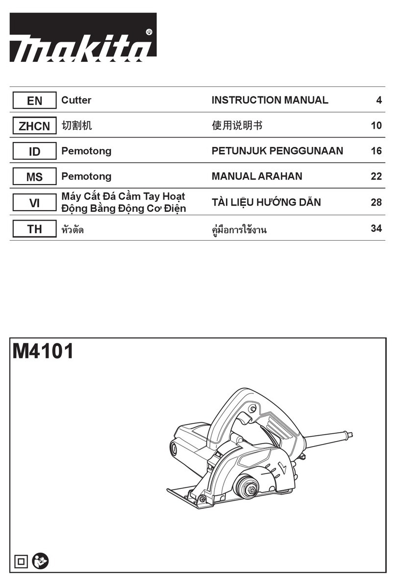
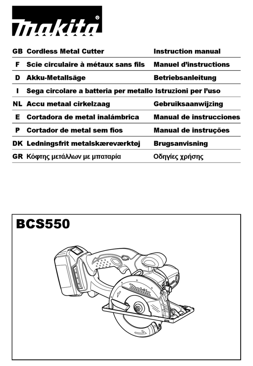
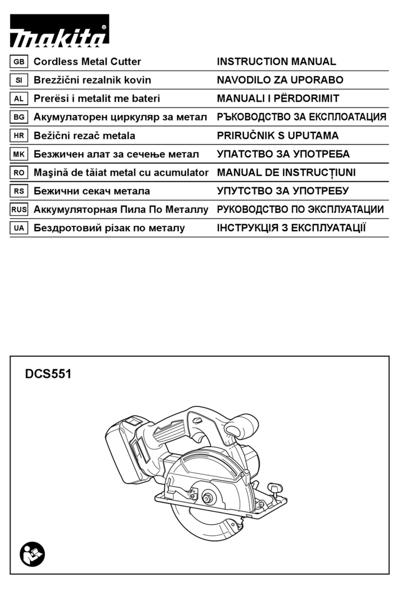
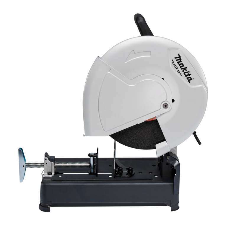
Makita CA5000 User manual

CA5000
EN Aluminum Groove Cutter INSTRUCTION MANUAL 6
SL Aluminijasti rezalnik utorov NAVODILA ZA UPORABO 12
SQ Prerësi i kanaleve në alumin MANUALI I PËRDORIMIT 19
BG Фреза за канали в алуминий РЪКОВОДСТВО ЗА
ЕКСПЛОАТАЦИЯ 26
HR Aluminijski rezač za utore PRIRUČNIK S UPUTAMA 34
МК Сечило за жлеб за
алуминиум УПАТСТВО ЗА УПОТРЕБА 40
SR Резач жлебова за
алуминијум УПУТСТВО ЗА УПОТРЕБУ 48
RO Maşină de canelat pentru
aluminiu MANUAL DE INSTRUCŢIUNI 55
UK Пазовий фрезер для
алюмінію
ІНСТРУКЦІЯ З
ЕКСПЛУАТАЦІЇ 62
RU Дисковый фрезер РУКОВОДСТВО ПО
ЭКСПЛУАТАЦИИ 70

Fig.1
Fig.2
Fig.3
Fig.4
Fig.5
Fig.6
1
2
Fig.7
1
Fig.8
2

1
4
2
3
Fig.9
2
1
Fig.10
1
Fig.11
2
1
3
Fig.12
1
Fig.13
Fig.14
2
1
Fig.15
1
2
3
4
Fig.16
3

1
Fig.17
1
2
3
4
Fig.18
1
Fig.19
2
1
Fig.20
1
2
Fig.21
1
Fig.22
Fig.23
1
Fig.24
4

1
Fig.25
1
Fig.26
1
Fig.27
5

6ENGLISH
ENGLISH (Original instructions)
SPECIFICATIONS
Model: CA5000
Groove cutter blade diameter 118.0 mm
Circular saw blade diameter 165.0 mm
Max. cutting depth (with groove cutter blade) 11.0 mm
Max. cutting depth (with circular saw blade) 36.0 mm
No load speed 2,200 - 6,400 min-1
Overall length 346 mm
Net weight 5.1 kg
Safety class /II
• Duetoourcontinuingprogramofresearchanddevelopment,thespecicationshereinaresubjecttochange
without notice.
• Specicationsmaydifferfromcountrytocountry.
• WeightaccordingtoEPTA-Procedure01/2003
Symbols
Thefollowingshowthesymbolsusedfortheequip-
ment. Be sure that you understand their meaning before
use.
Read instruction manual.
DOUBLEINSULATION
Groove cutter blade
Circular saw blade
OnlyforEUcountries
Donotdisposeofelectricequipment
together with household waste material! In
observanceoftheEuropeanDirective,on
WasteElectricandElectronicEquipment
and its implementation in accordance with
nationallaw,electricequipmentthathave
reached the end of their life must be col-
lected separately and returned to an envi-
ronmentally compatible recycling facility.
Intended use
Thetoolisspeciallyintendedforcuttinggrooveinto
composite boards made from aluminum, plastic, mineral
contained plastic, and similar materials.
Ifthetoolisequippedwithpropercircularsawblade,
the tool can be used for sawing wood and aluminum.
Power supply
Thetoolshouldbeconnectedonlytoapowersupplyof
the same voltage as indicated on the nameplate, and
canonlybeoperatedonsingle-phaseACsupply.They
are double-insulated and can, therefore, also be used
from sockets without earth wire.
Noise
ThetypicalA-weightednoiseleveldeterminedaccord-
ingtoEN60745:
Soundpressurelevel(LpA):82dB(A)
Soundpowerlevel(LWA):93dB(A)
Uncertainty(K):3dB(A)
WARNING: Wear ear protection.
Vibration
Thevibrationtotalvalue(tri-axialvectorsum)deter-
minedaccordingtoEN60745:
Workmode:aluminumcompositematerialgroove
cutting
Vibration emission (ah):2.5m/s2or less
Uncertainty(K):1.5m/s2
Workmode:cuttingwood
Vibration emission (ah,W):2.5m/s2or less
Uncertainty(K):1.5m/s2
Workmode:cuttingmetal
Vibration emission (ah,M):2.5m/s2or less
Uncertainty(K):1.5m/s2
NOTE:
Thedeclaredvibrationemissionvaluehasbeen
measured in accordance with the standard test method
and may be used for comparing one tool with another.
NOTE:
Thedeclaredvibrationemissionvaluemayalso
be used in a preliminary assessment of exposure.
WARNING:Thevibrationemissionduringactual
use of the power tool can differ from the declared
emission value depending on the ways in which the
tool is used.
WARNING: Be sure to identify safety measures
to protect the operator that are based on an estima-
tion of exposure in the actual conditions of use (taking
account of all parts of the operating cycle such as
the times when the tool is switched off and when it is
running idle in addition to the trigger time).

7ENGLISH
EC Declaration of Conformity
For European countries only
MakitadeclaresthatthefollowingMachine(s):
DesignationofMachine:AluminumGrooveCutter
ModelNo./Type:CA5000
ConformstothefollowingEuropeanDirectives:
2006/42/EC
Theyaremanufacturedinaccordancewiththefollowing
standardorstandardizeddocuments:EN60745
Thetechnicalleinaccordancewith2006/42/ECis
availablefrom:
Makita,Jan-BaptistVinkstraat2,3070,Belgium
22.1.2015
Yasushi Fukaya
Director
Makita,Jan-BaptistVinkstraat2,3070,Belgium
General power tool safety warnings
WARNING: Read all safety warnings and
all instructions. Failure to follow the warnings and
instructionsmayresultinelectricshock,reand/or
seriousinjury.
Save all warnings and instruc-
tions for future reference.
Theterm"powertool"inthewarningsreferstoyour
mains-operated (corded) power tool or battery-operated
(cordless) power tool.
Circular saw safety warnings
Cutting procedures
1.
DANGER: Keep hands away from cutting area
and the blade. Keep your second hand on auxil-
iary handle, or motor housing. If both hands are
holding the saw, they cannot be cut by the blade.
2. Do not reach underneath the workpiece.The
guard cannot protect you from the blade below the
workpiece.
3. Adjust the cutting depth to the thickness of
the workpiece.Lessthanafulltoothoftheblade
teeth should be visible below the workpiece.
4. Never hold piece being cut in your hands or
across your leg. Secure the workpiece to a
stable platform. It is important to support the
work properly to minimize body exposure, blade
binding, or loss of control.
►Fig.1
5. Hold the power tool by insulated gripping
surfaces only, when performing an operation
where the cutting tool may contact hidden
wiring or its own cord.Contactwitha"live"wire
will also make exposed metal parts of the power
tool"live"andcouldgivetheoperatoranelectric
shock.
6. When ripping, always use a rip fence or
straight edge guide.Thisimprovestheaccuracy
of cut and reduces the chance of blade binding.
7. Always use blades with correct size and shape
(diamond versus round) of arbour holes.
Blades that do not match the mounting hardware
of the saw will run eccentrically, causing loss of
control.
8. Never use damaged or incorrect blade wash-
ers or bolt.Thebladewashersandboltwere
specially designed for your saw, for optimum
performance and safety of operation.
Kickback causes and related warnings
— kickback is a sudden reaction to a pinched, bound
or misaligned saw blade, causing an uncontrolled
saw to lift up and out of the workpiece toward the
operator;
— when the blade is pinched or bound tightly by the
kerf closing down, the blade stalls and the motor
reaction drives the unit rapidly back toward the
operator;
— if the blade becomes twisted or misaligned in the
cut, the teeth at the back edge of the blade can dig
into the top surface of the wood causing the blade
toclimboutofthekerfandjumpbacktowardthe
operator.
Kickbackistheresultofsawmisuseand/orincorrect
operating procedures or conditions and can be avoided
by taking proper precautions as given below.
1. Maintain a rm grip with both hands on the
saw and position your arms to resist kickback
forces. Position your body to either side of the
blade, but not in line with the blade.Kickback
couldcausethesawtojumpbackwards,but
kickback forces can be controlled by the operator,
if proper precautions are taken.
2.
When blade is binding, or when interrupting a
cut for any reason, release the trigger and hold
the saw motionless in the material until the
blade comes to a complete stop. Never attempt
to remove the saw from the work or pull the saw
backward while the blade is in motion or kick-
back may occur. Investigate and take corrective
actions to eliminate the cause of blade binding.
3. When restarting a saw in the workpiece, centre
the saw blade in the kerf and check that saw
teeth are not engaged into the material. If saw
blade is binding, it may walk up or kickback from
the workpiece as the saw is restarted.
4. Support large panels to minimise the risk of
blade pinching and kickback.Largepanelstend
to sag under their own weight. Supports must be
placed under the panel on both sides, near the line
of cut and near the edge of the panel.
►Fig.2
►Fig.3
5. Do not use dull or damaged blades.
Unsharpenedorimproperlysetbladesproduce
narrow kerf causing excessive friction, blade
binding and kickback.
6. Blade depth and bevel adjusting locking levers
must be tight and secure before making cut. If
bladeadjustmentshiftswhilecutting,itmaycause
binding and kickback.
7. Use extra caution when sawing into existing
walls or other blind areas.Theprotrudingblade
maycutobjectsthatcancausekickback.

8ENGLISH
8. ALWAYS hold the tool rmly with both hands.
NEVER place your hand, leg or any part of your
body under the tool base or behind the saw,
especially when making cross-cuts. If kickback
occurs,thesawcouldeasilyjumpbackwardsover
yourhand,leadingtoseriouspersonalinjury.
►Fig.4
9. Never force the saw. Push the saw forward at a
speed so that the blade cuts without slowing.
Forcing the saw can cause uneven cuts, loss of
accuracy, and possible kickback.
Guard function
1. Check guard for proper closing before each
use. Do not operate the saw if guard does not
move freely and enclose the blade instantly.
Never clamp or tie the guard so that the blade
is exposed. If saw is accidentally dropped, guard
may be bent. Check to make sure that guard
moves freely and does not touch the blade or any
other part, in all angles and depths of cut.
2.
Check the operation and condition of the guard
return spring. If the guard and the spring are not
operating properly, they must be serviced before
use. Guard may operate sluggishly due to damaged
parts, gummy deposits, or a build-up of debris.
3.
Assure that the base plate of the saw will not
shift while performing the “plunge cut” when the
blade bevel setting is not at 90 °. Blade shifting
sideways will cause binding and likely kick back.
4. Always observe that the guard is covering the
blade before placing saw down on bench or
oor.Anunprotected,coastingbladewillcause
the saw to walk backwards, cutting whatever is in
its path. Be aware of the time it takes for the blade
to stop after switch is released.
Additional safety warnings
1.
Use extra caution when cutting damp wood, pres-
sure treated lumber, or wood containing knots.
Maintain smooth advancement of tool without decrease
in blade speed to avoid overheating the blade tips.
2. Do not attempt to remove cut material when
blade is moving. Wait until blade stops before
grasping cut material. Blades coast after turn off.
3. Avoid cutting nails. Inspect for and remove all
nails from lumber before cutting.
4. Place the wider portion of the saw base on
that part of the workpiece which is solidly
supported, not on the section that will fall off
when the cut is made. If the workpiece is short
or small, clamp it down. DO NOT TRY TO HOLD
SHORT PIECES BY HAND!
►Fig.5
5. Before setting the tool down after completing a
cut, be sure that the guard has closed and the
blade has come to a complete stop.
6. Never attempt to saw with the circular saw
held upside down in a vise. This is extremely
dangerous and can lead to serious accidents.
►Fig.6
7. Some material contains chemicals which may
be toxic. Take caution to prevent dust inhala-
tion and skin contact. Follow material supplier
safety data.
8. Do not stop the blades by lateral pressure on
the saw blade.
9. Do not use any abrasive wheels.
10. Only use the saw blade with the diameter that
is marked on the tool or specied in the man-
ual.Useofanincorrectlysizedblademayaffect
the proper guarding of the blade or guard opera-
tionwhichcouldresultinseriouspersonalinjury.
11. Keep blade sharp and clean. Gum and wood
pitch hardened on blades slows saw and
increasespotentialforkickback.Keepbladeclean
byrstremovingitfromtool,thencleaningitwith
gum and pitch remover, hot water or kerosene.
Never use gasoline.
12. Wear a dust mask and hearing protection when
use the tool.
SAVE THESE INSTRUCTIONS.
WARNING: DO NOT let comfort or familiarity
with product (gained from repeated use) replace
strict adherence to safety rules for the subject
product. MISUSE or failure to follow the safety
rules stated in this instruction manual may cause
serious personal injury.
FUNCTIONAL
DESCRIPTION
CAUTION: Always be sure that the tool is
switched off and unplugged before adjusting or
checking function on the tool.
Quick stop for 3, 4, or 6 mm board
thickness groove cutting
Byturningthequickstop,youcanchoosetheappro-
priate depth of groove cutting for 3, 4, or 6 mm board
thickness swiftly.
Thenumber,seenfromthehandleside,indicatesthe
workpiece board thickness.
Forneadjustmentofdepthofgroove,usethedepth
adjustingknob.
►Fig.7: 1. Quick stop 2.Depthadjustingknob
0 mm depth is set properly when the tool is shipped
from the factory, but if you changed the depth of groove
bytheadjustingknob,renethe0mmdepthasfollows:
1. Turnthequickstopto0mm.
2. Turnthedepthadjustingknobtoadjustthedepth.
3. Make sure that the blade does not make any
contact with work piece.
4. Holdthetoolrmlywithonehandonthefrontgrip
andtheotheronthetoolhandle.Pushinthelock-off
button, and turn the tool on.
5. Slowly press down the saw head fully, and check
whether the groove cutter blade does not contacts but
almost touches the workpiece. If not, stop the tool and
wait until the groove cutter blade stops completely, and
adjustthedepthbyturningthedepthadjustingknob
again.

9ENGLISH
Adjusting depth of cut
Toadjustdepthofcut,turnthedepthadjustingknob.
For deeper cut, turn it clockwise. For shallower cut, turn
it counterclockwise.
►Fig.8: 1.Depthadjustingknob
Sighting
Triangularmarkonthebaseindicatesthecenterofthe
groove cutter blade.
Whenusingwithgroovecutterblade,aligntheoutside
triangular mark with the cutting line.
Whenusingwithcircularsawblade(optionalacces-
sory), align the inside triangular mark with the cutting
line.
►Fig.9: 1. Base 2. Outside triangular mark 3. Inside
triangular mark 4. Cutting line
Switch action
CAUTION: Before plugging in the tool, always
check to see that the switch trigger actuates
properly and returns to the "OFF" position when
released.
Topreventtheswitchtriggerfrombeingaccidentally
pulled, a lock-off button is provided.
Tostartthetool,pushinthelock-offbuttonandpullthe
switch trigger.
Release the switch trigger to stop.
►Fig.10: 1.Lock-offbutton2. Switch trigger
Speed adjusting dial
CAUTION: The speed adjusting dial is not for
using low speed rated blades but for obtaining a
speed which is suitable to material of workpiece.
Useonlybladeswhichareratedforatleastthemaxi-
mumnoloadspeedstatedintheSPECIFICATIONS.
CAUTION:Thespeedadjustingdialcanbe
turned only as far as 6 and back to 1. Do not force it
past 6 or 1, or the speed adjusting function may
no longer work.
Thetoolspeedcanbeadjustedbyturningtheadjusting
dial. Higher speed is obtained when the dial is turned in
the direction of number 6; lower speed is obtained when
it is turned in the direction of number 1.
Refer to the table to select the proper speed for the
workpiece to be cut. However, the appropriate speed
may differ with the type or thickness of the workpiece. In
general, higher speeds will allow you to cut workpieces
faster but the service life of the blade will be reduced.
Number min-1
12,200
22,700
33,800
44,900
56,000
66,400
►Fig.11: 1.Speedadjustingdial
Guide plate
For aligning the guide rail (optional accessory) with the
cutting line, use the guide plate.
►Fig.12: 1. Guide plate 2.Plateedge3. Cutting line
1. Set the guide plate onto the guide rail near from
thecuttingstartpoint.Theplateedgerepresentsthe
centerofthegroovecutterblade.Aligntheplateedge
with the cutting line.
2. Then,setagaintheguideplateontheguiderail
nearthecuttingendpoint.Andaligntheplateedgewith
the cutting line again.
Other features
Thetoolsequippedwithelectronicfunctionareeasyto
operate because of the following features.
Overload protector
Whentheloadonthetoolexceedsadmissiblelevels,
power to the motor is reduced to protect the motor from
overheating.Whentheloadreturnstoadmissiblelev-
els, the tool will operate as normal.
Constant speed control
Electronicspeedcontrolforobtainingconstantspeed.
Possibletogetnenish,becausetherotatingspeedis
kept constant even under load condition.
Soft start feature
Soft start because of suppressed starting shock.
ASSEMBLY
CAUTION: Always be sure that the tool is
switched off and unplugged before carrying out
any work on the tool.
Hex wrench storage
Hexwrenchisstoredonthetool.Toremovehex
wrench,justpullitout.
Toinstallhexwrench,placeitonthegripandinsertitas
far as it goes.
►Fig.13: 1. Hex wrench
Removing or installing groove
cutter blade
CAUTION:
Do not use blades which do not comply
with the characteristics specied in these instructions.
CAUTION: Use only blades which are rated
for at least the maximum no load speed stated in
the SPECIFICATIONS.
CAUTION: Be sure the blade is installed with
teeth pointing up at the front of the tool.
CAUTION: Use only the Makita wrench to
install or remove the blade.

10 ENGLISH
Toremovethegroovecutterblade,performfollowing
steps:
1. Liedownthetoolasthemotorhousingandthe
basetouchingtheground.Theninsertthehexwrench
into the hex hole, push it in, and open the blade case
door by turning the hex wrench.
►Fig.14
2. Presstheshaftlockfullysothatthebladedoes
not revolve, then loosen the hex bolt counterclockwise
with the wrench.
►Fig.15: 1. Shaft lock 2. Hex bolt
3. Removethehexbolt,outerangeandblade.
►Fig.16: 1. Hex bolt 2.Outerange3. Groove cutter
blade 4.Innerange
Toinstalltheblade,followtheremovalprocedurein
reverse. Be sure to tighten the hex bolt clockwise
securely.Andclosethebladecasedoorafterinstalling
the blade.
Whenchangingblade,makesuretoalsocleanthe
guard of accumulated sawdust and chips as discussed
in the Maintenance section. Such efforts do not replace
the need to check guard operation before each use.
Using circular saw blade
Optional accessory
NOTE: In case using circular saw blade, the skirt is
not needed and it structually can not be installed.
Remove the skirt when using the circular saw blade.
Toinstallthecircularsawblade(optionalaccessory),
performthefollowingsteps:
1. Remove two bolts, and remove the skirt.
►Fig.17: 1. Skirt
2. Remove the groove cutter blade.
3. Slide in the circular saw blade from the opening
which the skirt had covered.
4. Install the circular saw blade in the same way as
thegroovecutterblade.Andclosethebladecasedoor
after installing the blade.
►Fig.18: 1. Hex bolt 2.Outerange3. Circular saw
blade 4.Innerange
5. Adjustdepthofcutbyturningthedepthadjusting
knob.
Rip fence (guide rule)
Optional accessory
CAUTION: Do not use the rip fence with the
groove cutter blade.Usetheripfenceonlywhen
using the tool with the circular saw blade (optional
accessory).
►Fig.19: 1. Rip fence (guide rule)
Thehandyripfenceallowsyoutodoextra-accurate
straight cuts. Simply slide the rip fence up snugly
against the side of the workpiece and secure it in
position with the screws on the front and the back of
the base. It also makes repeated cuts of uniform width
possible.
Overturning the rip fence (guide rule) also works as a
sub base for the tool.
Stopper for 2 to 3 mm depth of
cut when using circular saw blade
(optional accessory) and guide rail
(optional accessory)
►Fig.20: 1. Stopper 2. Red mark
Thistoolhasthestopperfor2to3mmdepthofcut
on the gear housing aside the rear handle when using
guide rail.
Splinter on the workpiece can be avoided by making a
passofthe2to3mmrstcutandthenmakeanother
pass of usual cut.
First, push in the stopper toward the circular saw blade
for obtaining 2 to 3 mm depth of cut.
Thenpullthebuttonbackforperformingfreedepthof
cut.
Make sure that the stopper is released and the red mark
can be seen for groove cutting operation.
Connecting a vacuum cleaner
For groove cutting operation, connect a Makita vacuum
cleaner to your tool.
Connect a hose of the vacuum cleaner to the dust port.
►Fig.21: 1. Vacuum cleaner 2.Dustport
OPERATION
CAUTION:Alwaysuseafrontgripandrear
handleandrmlyholdthetoolbybothfrontgripand
rear handle during operations.
Guide rail
Optional accessory
Alwaysusetheguiderailforgroovecuttingoperation.
Placethetoolontherearendoftheguiderail.
Turntwoadjustingscrewsonthetoolbasesothatthe
tool slides smoothly without a clatter.
►Fig.22: 1.Adjustingscrews
Groove cutting
CAUTION: Be sure to move the tool forward
in a straight line gently. Forcing or twisting the tool
may result in overheating the motor and dangerous
kickback,possiblycausingsevereinjury.
CAUTION: Never approach any part of your
body under the tool base when section cutting,
especially at starting.Doingsomaycauseserious
personalinjuries.Thebladeisexposedunderthetool
base.
CAUTION: Use eye protection to avoid injury.
CAUTION: For groove cutting operation,
always connect the tool to a vacuum cleaner.
CAUTION: Hold the tool rmly. The tool is
provided with both a front grip and rear handle.
Use both to best grasp the tool. If both hands are
holding saw, they cannot be cut by the blade.

11 ENGLISH
►Fig.23
1. Adjustthedepthofcut.
2. Set the tool on the guide rail.
3. Aligntheguiderailalongthecuttinglinewithusing
the guide plate. Make sure that the blade does not
make any contact with workpiece.
4. Pushinthelock-offbuttonandturnthetoolon,
and wait until the blade attains full speed.
5. Pressdownthetoolslowlytothepresetdepthof
cut, and simply move the tool forward over the work-
piecesurface,keepingitatandadvancingsmoothly
until the cutting is completed.
6. Whencuttingiscomplete,releaseswitch,waitfor
blade to stop and then withdraw tool.
Togetcleancuts,keepyourcuttinglinestraightand
your speed of advance uniform. If the cut fails to prop-
erly follow your intended cut line, do not attempt to
turn or force the tool back to the cut line.Doingso
may bind the blade and lead to dangerous kickback and
possibleseriousinjury.
Plunge cutting (Cutting-out)
WARNING: To avoid a kickback, be sure to
observe the following instructions.
1. Placethetoolontheguiderailwiththerearedge
oftoolbaseagainstaxedstoporequivalentwhichis
clamped on the guide rail.
►Fig.24: 1. Fixed stop
2. Holdthetoolrmlywithonehandonthefrontgrip
andtheotheronthetoolhandle.Pushinthelock-off
button, and turn the tool on, then wait until the blade
attains full speed.
3. Pressdownthesawheadslowlytothepreset
depth of cut, and move the tool forward to the desired
plunge position.
NOTE:Thetriangularmarkonthebladecaseshows
the approximate center of the blade.
►Fig.25: 1.Triangularmark
MAINTENANCE
CAUTION: Always be sure that the tool is
switched off and unplugged before attempting to
perform inspection or maintenance.
CAUTION: Clean out the guard to ensure
there is no accumulated sawdust and chips
which may impede the operation of the guarding
system.Adirtyguardingsystemmaylimittheproper
operation which could result in serious personal
injury.Themosteffectivewaytoaccomplishthis
cleaning is with compressed air. If the dust is being
blown out of the guard, be sure the proper eye
and breathing protection is used.
NOTICE: Never use gasoline, benzine, thinner,
alcohol or the like. Discoloration, deformation or
cracks may result.
Replacing carbon brushes
►Fig.26: 1.Limitmark
Check the carbon brushes regularly.
Replace them when they wear down to the limit mark.
Keepthecarbonbrushescleanandfreetoslipinthe
holders. Both carbon brushes should be replaced at the
sametime.Useonlyidenticalcarbonbrushes.
1. Useascrewdrivertoremovethebrushholder
caps.
2. Takeouttheworncarbonbrushes,insertthenew
ones and secure the brush holder caps.
►Fig.27: 1. Brush holder cap
TomaintainproductSAFETYandRELIABILITY,
repairs,anyothermaintenanceoradjustmentshould
beperformedbyMakitaAuthorizedorFactoryService
Centers, always using Makita replacement parts.
OPTIONAL
ACCESSORIES
CAUTION: These accessories or attachments
are recommended for use with your Makita tool
specied in this manual.Theuseofanyother
accessories or attachments might present a risk of
injurytopersons.Onlyuseaccessoryorattachment
for its stated purpose.
If you need any assistance for more details regard-
ing these accessories, ask your local Makita Service
Center.
• Guiderail
• 90°groovecutterblade
• 135°groovecutterblade
• Guideplate
• Circularsawblade
• Ripfence(Guiderule)
• Clamp
• Hexwrench
• Sheetsetforguiderail
• Rubbersheetsetforguiderail
• Positionsheetforguiderail
• Bevelguideset
NOTE: Some items in the list may be included in the
toolpackageasstandardaccessories.Theymay
differ from country to country.

12 SLOVENŠČINA
SLOVENŠČINA (Originalna navodila)
TEHNIČNI PODATKI
Model: CA5000
Premerrezilarezalnikautorov 118,0 mm
Premerrezilakrožnežage 165,0 mm
Maksimalna globina reza (z rezilom rezalnika utorov) 11,0 mm
Maksimalnaglobinareza(zrezilomkrožnežage) 36,0 mm
Hitrost brez obremenitve 2.200 - 6.400 min-1
Celotnadolžina 346 mm
Netoteža 5,1 kg
Razredzaščite /II
• Kernenehnoopravljamoraziskaveinrazvijamosvojeizdelke,selahkotehničnipodatkivtemdokumentu
spremenijobrezobvestila.
• Tehničnipodatkiselahkorazlikujejooddržavedodržave.
• TežavskladuspostopkomEPTA01/2003
Simboli
Naslednjisimboliseuporabljajovpovezavisstrojem.
Preduporaboizdelkaseobveznoseznaniteznjihovim
pomenom.
Preberitenavodilazauporabo.
DVOJNAIZOLACIJA
Rezilo rezalnika utorov
Rezilokrožnežage
SamozadržaveEU
Električnegaorodjaneodlagajteskupaj
zgospodinjskimiodpadki!Vskladuz
Evropskodirektivooodpadnielektričniin
elektronskiopremiinznjenimizvajanjem
vskladuzdržavnozakonodajosemora
električnaopremaspretečenoživljenjsko
dobozbiratiločenoindostavitivokoljsko
združljivoustanovozarecikliranje.
Predvidena uporaba
Orodjejenamenjenoizključnozarezanjeutorovv
sestavljeneplošče,izdelaneizaluminija,plastike,pla-
stike z mineralnimi primesmi in podobnih snovi.
Čejeorodjeopremljenozustreznimrezilomkro-
žnežage,lahkoorodjeuporabitezažaganjelesain
aluminija.
Priključitev na električno omrežje
Napetostelektričnegaomrežjasemoraujematis
podatkinatipskiploščici.Strojdelujesamozenofazno
izmeničnonapetostjo.Strojjepoevropskihsmernicah
dvojnozaščitnoizoliran,zatosegalahkopriključitudiv
vtičnicebrezozemljitvenegavoda.
Hrup
ObičajnaA-ovrednotenaravenhrupavskladuz
EN60745:
Ravenzvočnegatlaka(LpA):82dB(A)
Ravenzvočnemoči(LWA):93dB(A)
Odstopanje(K):3dB(A)
OPOZORILO: Uporabljajte zaščito za sluh.
Vibracije
Skupnevrednostivibracij(vektorskavsotatrehosi)v
skladuzEN60745:
Delovninačin:Rezanjeutorovvsestavljeneploščeiz
aluminija
Emisijevibracij(ah):2,5m/s2alimanj
Odstopanje(K):1,5m/s2
Delovninačin:rezanjelesa
Emisijevibracij(ah,W):2,5m/s2alimanj
Odstopanje(K):1,5m/s2
Delovninačin:rezanjekovine
Emisijevibracij(ah, M):2,5m/s2alimanj
Odstopanje(K):1,5m/s2
OPOMBA:Navedenavrednostoddajanjavibracij
jebilaizmerjenavskladusstandardnimimetodami
testiranjainselahkouporabljazaprimerjavoorodij.
OPOMBA:Navedenavrednostoddajanjavibra-
cijselahkouporabljatudipripredhodnioceni
izpostavljenosti.
OPOZORILO:
Oddajanjevibracijmeddejansko
uporaboelektričnegaorodjaselahkorazlikujeodnavedene
vrednostioddajanja,odvisnoodnačinauporabeorodja.
OPOZORILO:Upravljavecmorazalastnozaš-
čitopoznativarnostneukrepe,kitemeljijonaoceni
izpostavljenostivdejanskihpogojihuporabe(poleg
časaproženjajetrebaupoštevaticelotendelovni
cikel,vključnosčasom,kojeorodjeizklopljeno,in
časom,kodelujevprostemteku).

13 SLOVENŠČINA
ES Izjava o skladnosti
Samo za evropske države
DružbaMakitaizjavlja,dasonaslednjiizdelki:
Oznakastroja:Aluminijastirezalnikutorov
Številka/tipmodela:CA5000
skladniznaslednjimievropskimidirektivami:
2006/42/ES
Izdelanisovskladuznaslednjimstandardomalistan-
dardiziranimidokumenti:EN60745
Tehničnadokumentacijavskladuzdirektivo2006/42/
ESjenavoljonanaslovu:
Makita,Jan-BaptistVinkstraat2,3070,Belgija
22.1.2015
Yasushi Fukaya
Direktor
Makita,Jan-BaptistVinkstraat2,3070,Belgija
Splošna varnostna opozorila za
električno orodje
OPOZORILO: Preberite vsa varnostna opo-
zorila in navodila. Neupoštevanjeopozorilinnavodil
lahkoprivededoelektričnegaudara,požarain/ali
resnih telesnih poškodb.
Shranite vsa opozorila in navo-
dila za poznejšo uporabo.
Izraz„električnoorodje“vopozorilihsenanašanavaše
električnoorodje(skablom)alibaterijskoelektrično
orodje(brezkabla).
Varnostna opozorila za uporabo
krožne žage
Postopki rezanja
1. NEVARNOST: Ne približujte rok območju
rezanja in rezilu. Drugo roko imejte na pomož-
nem ročaju ali ohišju motorja.Čedržitežagoz
obemarokama,jurezilonemorepoškodovati.
2. Ne segajte pod obdelovanca.Ščitnikvaspod
obdelovancem ne more varovati pred rezilom.
3. Prilagodite globino rezanja debelini obdelo-
vanca.Podobdelovancemnesmebitividnaveč
kotenadolžinazobca.
4. Med rezanjem nikoli ne držite obdelovanca v
rokah ali med nogami. Pritrdite obdelovanca
na stabilno podlago.Pomembnoje,dasiustre-
znopomagatemeddelom,dazmanjšateizpo-
stavljenosttelesa,možnostzagozditverezilaali
izgubo nadzora.
►Sl.1
5. Če obstaja nevarnost, da bi z rezilnim orodjem
prerezali skrito električno napeljavo ali lasten
kabel, držite električno orodje samo na izoli-
ranih držalnih površinah. Ob stiku z vodniki pod
napetostjodobijonapetostvsineizoliranikovinski
delielektričnegaorodja,zaradičesarlahkoupo-
rabnikutrpielektričniudar.
6. Med vzporednim rezanjem vedno uporabite
vzporedni prislon ali vodilo z ravnim robom. S
tembosteizboljšalinatančnostrezainzmanjšali
možnostzagozditverezila.
7. Vedno uporabljajte rezila prave velikosti in
oblike osnih lukenj (diamantna ali krožna).
Rezila,kijihnimogočeustreznonamestitina
orodje,bododelovalaekscentrično,karbo
povzročiloizgubonadzora.
8. Nikoli ne uporabljajte poškodovanih ali nepra-
vilnih tesnil ali vijakov rezila.Tesnilainvijaki
rezilasobilaposebejnarejenazavašožago,da
zagotovijooptimalnoučinkovitostinvarnostpri
delu.
Vzroki za povratni udarec in s tem povezana
opozorila
— povratniudarecjenenadnareakcijapristisnjenju,
zagozdenjualineporavnanemžaginemlistu,ki
povzročinenadzorovandvigžageizobdelovanca
protiupravljavcu;
— čejerezilostisnjenoalitrdnozagozdenovzapi-
rajočisešpranji,seustaviinreakcijamotorjahitro
vržeenotonazajprotiupravljavcu;
— česerezilomedrezomzvijealijenapačno
poravnano,selahkozobcinazadnjemroburezila
zataknejovzgornjopovršinolesa,karpovzroči,da
rezilopadeizšpranjeinskočiprotiupravljavcu.
Povratniudarecjeposledicanestrokovnegaravnanja
zžagoin/alineugodnihokoliščin.Preprečitegalahkoz
upoštevanjemspodajnavedenihopozoril.
1. Trdno držite žago z obema rokama in name-
stite roki, da se uprete silam povratnega
udarca. Namestite telo na katero koli stran
rezila in ne poravnano z rezilom.Povratniuda-
reclahkopovzročiskokžagenazaj,vendarlahko
silepovratnegaudarcaupravljavecnadzoruje,če
izvede pravilne varnostne ukrepe.
2. Ko se rezilo zatakne ali če iz katerega koli
razloga prekinete z rezanjem, spustite spro-
žilnik in negibno držite žago v materialu,
dokler se rezilo popolnoma ne ustavi. Nikoli
ne skušajte odstraniti žage iz obdelovanca in
je ne poskušajte povleči nazaj, dokler se žaga
premika. V nasprotnem primeru lahko pride do
povratnega udarca.Preveriteinodpravitevzrok
oviranjarezila.
3. Kadar ponovno zaganjate žago v obdelovancu,
poravnajte žagin list v špranji in se prepričajte,
da žagini zobci niso zagozdeni v materialu.Če
seježaginlistzagozdil,selahkopremakneali
udariizobdelovanca,koznovazaženetežago.
4. Pod velike plošče postavite podporo, da
zmanjšate možnost zagozdenja rezila ali
povratnega udarca.Velikeploščeselahkozaradi
lastnetežepovesijo.Podporejetrebapostaviti
podploščonaobehstranehvbližinilinijerezain
blizurobaplošče.
►Sl.2
►Sl.3
5. Ne uporabljajte topih ali poškodovanih rezil.
Nenabrušenaalinepravilnonastavljenarezila
naredijoozkošpranjo,karpovzročičezmerno
trenje,zagozdenjerezilainpovratniudarec.

14 SLOVENŠČINA
6. Ročici za nastavljanje globine reza in prila-
goditev poševnosti morata biti trdno in varno
pritrjeni pred začetkom rezanja.Česeprilago-
jenipoložajrezilamedrezanjemspremeni,lahko
povzročioviranjeinpovratniudarec.
7. Bodite še posebej previdni, kadar režete v
obstoječe stene ali druga slepa območja.
Rezilolahkoprerežepredmete,kilahkopovzročijo
povratni udarec.
8.
VEDNO trdno držite orodje z obema rokama.
NIKOLI ne polagajte rok, nog ali katerega koli
drugega dela telesa pod osnovno ploščo orodja
ali za žago, zlasti kadar izvajate prečne reze. V
primerupovratnegaudarcalahkožagaodskočinazaj
prekovašerokeinpovzročihudetelesnepoškodbe.
►Sl.4
9. Nikoli ne pritiskajte žage. Potisnite žago naprej
s hitrostjo, pri kateri rezilo reže brez upočas-
njevanja.Pritiskanjenažagolahkopovzroči
neravnereze,nenatančnostinmorebitenpovratni
udarec.
Funkcija ščitnika
1.
Pred vsako uporabo preverite, ali se ščitnik pra-
vilno zapira. Ne uporabljajte žage, če se ščitnik
ne premika prosto in takoj ne zapre rezila. Nikoli
ne zatikajte ali zavežite ščitnika tako, da je rezilo
odkrito.Čevamžagaponesrečipade,selahko
ščitnikzvije.Prepričajtese,daseščitnikprosto
premika in se ne dotika rezila ali katerega koli dela
pri vseh kotih in globinah reza.
2.
Preverite delovanje in stanje povratne vzmeti
ščitnika. Če ščitnik in vzmet ne delujeta pra-
vilno, ju je treba pred uporabo servisirati.Ščitnik
lahkodelujepočasizaradipoškodovanihdelov,
odloženihsnovinagumialinabranihostružkov.
3. Zagotovite, da se osnovna plošča žage ne
bo premaknila med izvajanjem „pogreznega
reza“, kadar poševna nastavitev rezila ni 90°.
Stranskipremikrezilabopovzročilzagozditevin
verjetnopovratniudarec.
4. Preden odložite žago na mizo ali tla, vedno
pazite, da ščitnik pokriva rezilo.Nezaščiteno
rezilovprostemtekubopovzročilopremik
žagenazaj,kiborezalavse,karjibonapoti.
Upoštevajtečas,kijepotrebenzazaustavitev
rezila, ko izpustite stikalo.
Dodatna varnostna opozorila
1. Bodite posebej previdni pri rezanju vlažnega
lesa, s tlakom obdelanega lesa ali grčavega
lesa.Orodjemoranapredovatigladkobrezzmanj-
šanjahitrostirezila,dasepreprečipregrevanje
konice rezila.
2. Ne poskušajte odstraniti odrezanega mate-
riala, medtem ko se rezilo premika. Preden
primete rezan material, počakajte, da se rezilo
ustavi.Rezilojepoizklopuvprostemteku.
3. Izogibajte se rezanju žebljev. Pred rezanjem
poiščite vse žeblje in jih odstranite iz lesa.
4. Širši del podstavka žage postavite na tisti
del obdelovanca, ki je trdno podprt, in ne
na del, ki bo po končanem rezu odpadel. Če
je obdelovanec kratek ali majhen, ga pritr-
dite. NE POSKUŠAJTE DRŽATI KRATKEGA
OBDELOVANCA V ROKI!
►Sl.5
5. Pred odložitvijo orodja po končanem rezu se
prepričajte, da se je ščitnik zaprl in se je rezilo
popolnoma ustavilo.
6.
Nikoli ne poskušajte žagati s krožno žago, tako da
jo vpnete v primež obrnjeno na glavo. To je izje-
mno nevarno in lahko povzroči hudo nesrečo.
►Sl.6
7. Nekateri materiali vsebujejo kemikalije, ki so
lahko strupene. Bodite previdni ter preprečite
vdihavanje prahu in stik s kožo. Upoštevajte
varnostne podatke dobavitelja materiala.
8. Ne zaustavljajte rezila z bočnim pritiskom na
žagin list.
9. Ne uporabljajte abrazivnih plošč.
10.
Uporabljajte le rezila žage s premerom, ki je
označen na orodju ali naveden v priročniku.
Uporabarezilanepravilnevelikostilahkovplivana
ustreznozaščitorezilaalidelovanješčitnika,zaradi
česarlahkopridedohudihtelesnihpoškodb.
11.
Rezilo mora biti ostro in čisto. Guma in lesna
smola,strjenanarezilu,upočasnjuježagoinpoveča
možnostpovratnegaudarca.Ohranitečistorezilo,
takodaganajprejodstranitezorodja,gaočistites
sredstvomzaodstranjevanjegumeinsmole,vročo
vodoalikerozinom.Nikolineuporabljajtebencina.
12. Med uporabo orodja nosite protiprašno masko
in zaščito za sluh.
SHRANITE TA NAVODILA.
OPOZORILO: NE dovolite, da bi zaradi udob-
nejšega dela ali znanja o uporabi izdelka (prido-
bljenega z večkratno uporabo) opustili strogo
upoštevanje varnostnih zahtev v okviru pravilne
uporabe orodja. ZLORABA ali neupoštevanje var-
nostnih zahtev v teh navodilih za uporabo lahko
povzroči resne telesne poškodbe.
OPIS DELOVANJA
POZOR: Pred vsako nastavitvijo ali pregle-
dom nastavitev orodja se prepričajte, da je orodje
izklopljeno in izključeno z električnega omrežja.
Hitra ustavitev za rezanje utorov v
plošče debeline 3, 4 ali 6 mm
Čeobrnetegumbzahitroustavitev,lahkopriročno
izbereteprimernoglobinozarezanjeutorovvplošče
debeline 3, 4 ali 6 mm.
Število,kigaviditesstraniročice,pomenidebelino
ploščeobdelovanca.
Zanatančnonastavitevglobineutorauporabitegumb
za nastavitev globine.
►Sl.7: 1. Hitra ustavitev 2. Gumb za nastavitev
globine
Obdostaviorodjaiztovarnejepravilnonastavljena
globina0mm,čepasteprekgumbazanastavitev
spremenili globino, znova nastavite globino 0 mm, in
sicernanaslednjinačin:

15 SLOVENŠČINA
1. Gumb za hitro ustavitev obrnite na 0 mm.
2. Globinonastavitezvrtenjemgumbazanastavitev
globine.
3. Rezilo ne sme priti v stik z obdelovancem.
4. Trdnodržiteorodjezenorokozasprednjedržalo
inzdrugozaročajorodja.Pritisnitesprostilnigumbin
vklopiteorodje.
5. Počasidokoncapotisniteglavožagenavzdolin
preverite,alijerezilorezalnikautorovtikobobdelo-
vancu(nesmesegadotikati).Čeni,ustaviteorodjein
počakajte,daserezilorezalnikautorovpovsemzaus-
tavi, nato pa prilagodite globino tako, da znova obrnete
gumb za nastavitev globine.
Nastavljanje globine rezanja
Globinorezanjanastavitetako,daobrnetegumbza
nastavitev globine.
Zaglobljirezgaobrnitevsmeriurnegakazalca.Zaplit-
kejširezgaobrnitevnasprotnismeriurnegakazalca.
►Sl.8: 1. Gumb za nastavitev globine
Poravnanje z linijo reza
Trikotnaoznakanaosnovniploščipomenisredinorezila
rezalnika utorov.
Kadarzorodjemuporabljaterezilorezalnikautorov,
poravnajtezunanjotrikotnooznakozlinijoreza.
Kadarzorodjemuporabljaterezilokrožnežage(doda-
tnipribor),poravnajtenotranjotrikotnooznakozlinijo
reza.
►Sl.9: 1.Osnovnaplošča2.Zunanjatrikotnaoznaka
3.Notranjatrikotnaoznaka4.Linijareza
Delovanje stikala
POZOR: Pred priključitvijo orodja na elek-
trično omrežje se vedno prepričajte, da je stikalo
brezhibno in se vrača v položaj za izklop (OFF), ko
ga spustite.
Zapreprečevanjenenamernesprožitvestikalajename-
ščensprostilnigumb.
Zazagonorodjahkratipritisnitesprostilnigumbin
sprožilnostikalo.
Zaizklopspustitestikalo.
►Sl.10: 1. Sprostilni gumb 2.Sprožilnostikalo
Gumb za nastavitev hitrosti
POZOR: Gumb za nastavitev hitrosti se ne
uporablja za rezila žage, ki so namenjena za
nizke hitrosti, ampak za pridobivanje hitrosti, ki
je primerna za material obdelovanca.Uporabljajte
lerezila,kisonamenjenazanajmanjnajvišjohitrost
brezobremenitve,navedenovpoglavjuTEHNIČNI
PODATKI.
POZOR:Številčnicozaizbirohitrostilahkoobr-
netesamodo6innazajdo1.Na silo je ne vrtite
onkraj položajev 6 ali 1, ker lahko zaradi tega
pride do izpada funkcije nastavitve hitrosti.
Hitrostorodjalahkonastavitezobračanjemgumbaza
nastavitevhitrosti.Višjohitrostnastavite,češtevilčnico
obrnetevsmerištevilke6,nižjohitrostpa,čejoobrnete
v smeri številke 1.
Glejtetabelozaizbiroustreznehitrostizaobdelovanca,
kigabosterezali.Optimalnahitrostjeodvisnatudiod
vrsteindebelineobdelovanca.Večjahitrostpraviloma
pospešihitrostrezanja,vendartudiskrajšuježivljenjsko
dobožaginegalista.
Številka min-1
12.200
22.700
33.800
44.900
56.000
66.400
►Sl.11: 1. Gumb za nastavitev hitrosti
Vodilna plošča
Zaporavnavanjevodila(dodatnipribor)zlinijoreza
uporabitevodilnoploščo.
►Sl.12: 1.Vodilnaplošča2.Robplošče3.Linijareza
1. Vodilnoploščopostavitenavodilovbližinizačetne
točkerezanja.Robploščepredstavljasredinorezila
rezalnikautorov.Poravnajterobploščezlinijoreza.
2. Natoznovapostavitevodilnoploščonavodilo
vbližinizačetnetočkerezanja.Znovaporavnajterob
ploščezlinijoreza.
Druge funkcije
Stroji,opremljenizelektronskimifunkcijami,imajo
naslednjemožnosti,kilajšajouporabo.
Varovalo pred preobremenitvijo
Čeobremenitevorodjapresežedovoljenenivoje,se
močmotorjazmanjša,dasemotorzaščitipredpregre-
vanjem.Koseobremenitevvrnenadovoljenevred-
nosti,boorodjenadaljevalozobičajnimdelovanjem.
Uravnavanje konstantnega števila
vrtljajev
Elektronskinadzorhitrostizakonstantnoštevilovrtlja-
jev.Možnostnekončneobdelave,sajjehitrostrotacije
konstantnatudivstanjuobremenitve.
Funkcija mehkega zagona
Mehkizagonomogočadušenjesunkovobzagonu.
MONTAŽA
POZOR: Pred vsakim posegom v orodje se
prepričajte, da je orodje izklopljeno in izključeno z
električnega omrežja.

16 SLOVENŠČINA
Shranjevanje inbus ključa
Inbusključjeshranjennaorodju.Zaodstranitevinbus
ključagaenostavnoizvlecite.
Zanamestitevinbusključaganamestitenadržalodo
omejitve.
►Sl.13: 1.Inbusključ
Odstranjevanje ali nameščanje
rezila rezalnika utorov
POZOR: Ne uporabljajte rezil, ki niso skladna
z značilnostmi, navedenimi v teh navodilih.
POZOR: Uporabljajte le rezila, ki so name-
njena za najmanj najvišjo hitrost brez obremeni-
tve, navedeno v poglavju TEHNIČNI PODATKI.
POZOR: Prepričajte se, da je rezilo name-
ščeno z navzgor obrnjenimi zobmi na čelni strani
orodja.
POZOR: Za odstranitev ali namestitev rezila
uporabljajte samo Makita inbus ključ.
Rezilorezalnikautorovodstranitetako:
1. Orodjepoložitetako,daseohišjemotorjain
osnovnaploščadotikatatal.Natovstaviteinbusključv
šestroboluknjo,potisniteganavznoterinodpritevratca
ohišjarezilatako,daobrneteinbusključ.
►Sl.14
2. Dokoncapritisnitezaporovretena,takodase
rezilonemorevrteti,innatosključemsprostitešestrobi
vijakvnasprotnismeriurnegakazalca.
►Sl.15: 1.Zaporavretena2.Šestrobivijak
3. Odstranitešestrobivijak,zunanjoprirobnicoin
rezilo.
►Sl.16: 1.Šestrobivijak2.Zunanjaprirobnica
3. Rezilo rezalnika utorov 4.Notranja
prirobnica
Novo rezilo namestite v obratnem vrstnem redu.
Šestrobi vijak morate trdno zategniti v smeri urnega
kazalca.Ponamestitvirezilazapritevratcaohišja
rezila.
Kadarzamenjujeterezilo,moratetudiizščitnikovočistiti
nakopičenožagovinoinostružke,kotjeomenjenov
razdelkuVzdrževanje.Ševednopajetrebapredvsako
uporabopreveritidelovanješčitnika.
Uporaba rezila krožne žage
Dodatna oprema
OPOMBA:Čeuporabljaterezilokrožnežage,ne
nameščajteovoja.Vnasprotnemprimerurezilokro-
žnežagetrčivovojinpoškodujeorodje.
Rezilokrožnežage(dodatnipribor)namestitetako:
1. Odstranitedvasornikainovoj.
►Sl.17: 1.Ovoj
2. Odstranite rezilo rezalnika utorov.
3. Skoziodprtino,kijojeprekrivalovoj,potisnite
rezilokrožnežage.
4. Namestiterezilokrožnežagenaenaknačinkot
rezilorezalnikautorov.Ponamestitvirezilazaprite
vratcaohišjarezila.
►Sl.18: 1.Šestrobivijak2.Zunanjaprirobnica
3.Rezilokrožnežage4.Notranjaprirobnica
5. Globinorezanjanastavitetako,daobrnetegumb
za nastavitev globine.
Vzporedni prislon (vodilno ravnilo)
Dodatna oprema
POZOR: Vzporednega prislona ne upo-
rabljajte skupaj z rezilom rezalnika utorov.
Vzporedniprislonuporabljajtele,kadarzorodjem
uporabljaterezilokrožnežage(dodatnipribor).
►Sl.19: 1. Vzporedni prislon (vodilno ravnilo)
Priročenvzporedniprislonomogočaizjemnonatančne
ravne reze. Vzporedni prislon namestite ob stran obde-
lovancaingapritrditezvijakomanasprednjoinzadnjo
stranosnovneplošče.Takolahkoizdelujetetudiserij-
ske reze enake širine.
Čeobrnetevzporedniprislon(vodilnoravnilo),selahko
uporabljatudikotpomožnaosnovnaploščaorodja.
Omejevalnik za globino reza 2 do 3
mm pri rezanju z rezilom krožne žage
(dodatni pribor) in vodilom (dodatni
pribor)
►Sl.20: 1.Omejevalnik2.Rdečaoznaka
Toorodjeimaomejevalnikzaglobinoreza2do3mm
naohišjuorodjapolegzadnjegaročaja,kadaruporab-
ljatevodilo.
Razcepljanjeobdelovancalahkopreprečitetako,da
izvedete prvi rez globine 2 do 3 mm in nato izvedete
običajenrez.
Najprejpotisniteomejevalnikprotirezilukrožnežage,
da zagotovite globino reza 2 do 3 mm.
Natopovlecitegumbnazajzaprostoglobinoreza.
Pripostopkurezanjautorovmorabitiomejevalnikspro-
ščeninrdečaoznakavidna.
Povezovanje sesalnika
Prirezanjuutorovnaorodjepriključitesesalnikzaprah
Makita.
Vvratazasesalnikpriključitecevsesalnikazaprah.
►Sl.21: 1. Sesalnik za prah 2. Vrata za sesalnik
UPRAVLJANJE
POZOR:Vednouporabljajtesprednjiročajin
zadnjedržalo;meddelovanjemorodjetrdnodržiteza
oba,sprednjiročajinzadnjedržalo.

17 SLOVENŠČINA
Vodilo
Dodatna oprema
Prirezanjuutorovvednouporabljajtevodilo.
Namestiteorodjenazadnjikonecvodila.
Zavrtitedvaprilagoditvenavijakaosnovneplošče
orodjatako,daorodjegladkodrsibrezropotanja.
►Sl.22: 1.Prilagoditvenivijaki
Rezanje utorov
POZOR: Stroj pomikajte vedno naprej, narav-
nost in z zmerno silo.Zvijanjeinuporabljanjesilena
orodjulahkopovzročipregrevanjemotorjainnevarni
povratniudarec,kilahkopovzročiresnetelesne
poškodbe.
POZOR: Med rezanjem kosov nikoli ne
približujte delov telesa pod osnovno ploščo
orodja, zlasti na začetku reza.Tolahkoprivededo
hudihtelesnihpoškodb.Rezilojeizpostavljenopod
osnovnoploščoorodja.
POZOR: Za preprečevanje poškodb uporabite
zaščito za oči.
POZOR: Pri rezanju utorov orodje vedno
priključite na sesalnik za prah.
POZOR: Trdno držite orodje. Orodje je opre-
mljeno s sprednjim držalom in zadnjim ročajem.
Za najboljši oprijem orodja uporabite oboje.Če
oberokidržitažago,rezilonemorezarezativanju.
►Sl.23
1. Nastaviteglobinorezanja.
2. Orodjepostavitenavodilo.
3. Zvodilnoploščoporavnajtevodilovzdolžlinije
reza. Rezilo ne sme priti v stik z obdelovancem.
4. Pritisnitesprostilnigumbinvklopiteorodjeter
počakajte,darezilodosežepolnoštevilovrtljajev.
5. Počasipritisniteorodjenavzdoldoprednastav-
ljeneglobinerezainpreprostopomikajteorodječez
površinoobdelovanca,pričemerohraniteobdelovanec
vravnempoložaju,terenakomernonapredujte,dokler
nedokončatereza.
6. Pokoncurezanjaspustitestikalo,počakajte,dase
reziloustavi,innatoizvleciteorodje.
Čeželite,daborezčistinraven,natančnosledite
zarisanirezalnilinijiinohraniteenakomernosilo
pomika.Čeprirezanjuzaideteiznačrtovanelinije
reza, ne poskušajte obračati ali siliti orodja nazaj v
linijo reza.Stemlahkozagozditereziloterpovzročite
nevarni povratni udarec in morebitne hude telesne
poškodbe.
Žaganje s pogrezanjem (izrezovanje)
OPOZORILO: Za preprečevanje povratnega
udarca upoštevajte naslednja navodila.
1. Namestiteorodjenavodilozzadnjimrobom
osnovneploščeorodjanaslonjenimnaksnoustavljalo
(alienakovrednooporo),kijevpetovvodilo.
►Sl.24: 1.Fiksnoustavljalo
2. Trdnodržiteorodjezenorokozasprednjedržalo
inzdrugozaročajorodja.Pritisnitesprostilnigumbin
vklopiteorodjeterpočakajte,darezilodosežepolno
številovrtljajev.
3. Počasipritisniteglavožagenavzdoldopred-
nastavljeneglobineinpremakniteorodjenaprejvželeni
pogreznjenipoložaj.
OPOMBA:Trikotnaoznakanaohišjurezilaoznačuje
približnosredinorezila.
►Sl.25: 1.Trikotnaoznaka
VZDRŽEVANJE
POZOR: Preden se lotite pregledovanja ali
vzdrževanja orodja, se vedno prepričajte, da je
orodje izklopljeno in vtič izvlečen iz vtičnice.
POZOR: Iz ščitnika odstranite nabrano
žagovino in ostružke, saj je lahko v nasprotnem
primeru delovanje varovalnega sistema ovirano.
Umazanvarovalnisistemlahkoovirapravilnodelo-
vanje,karlahkoprivededoresnetelesnepoškodbe.
Najučinkovitejšinačinčiščenjaječiščenjesstisnje-
nim zrakom. Med razpihovanjem prahu iz ščitnikov
poskrbite za ustrezno zaščito oči in dihal.
OBVESTILO: Nikoli ne uporabljajte bencina,
razredčila, alkohola ali podobnega sredstva. V
tem primeru se lahko orodje razbarva ali defor-
mira oziroma lahko nastanejo razpoke.
Menjava karbonskih krtačk
►Sl.26: 1.Mejnaoznačba
Karbonskikrtačkipreverjajteredno.
Kostaobrabljenidomejneoznačbe,juzamenjajte.
Karbonskikrtačkimoratabitičisti,dalahkoneovirano
zdrsnetavdržali.Zamenjajteobekarbonskikrtački
naenkrat.Uporabljajteleenakikarbonskikrtački.
1. Zizvijačemodstranitepokrovadržalkrtačk.
2. Izvleciteizrabljenikarbonskikrtački,namestite
noviinprivijteobapokrovadržalkrtačk.
►Sl.27: 1.Pokrovdržalakrtačk
VARNOinZANESLJIVOdelovanjetegaizdelkabo
zagotovljenole,čebostepopravila,vzdrževanjein
nastavitveprepustilipooblaščenemuservisuzaorodja
Makitaalitovarniškemuosebju,kivgrajujeizključno
originalne nadomestne dele.
DODATNA OPREMA
POZOR: Ta dodatni pribor ali pripomočki so
predvideni za uporabo z orodjem Makita, ki je
opisano v teh navodilih za uporabo.Priuporabi
drugegapriboraalipripomočkovobstajanevarnost
telesnihpoškodb.Dodatnipriboralipripomočke
uporabljajtesamozanavedeninamen.

18 SLOVENŠČINA
Zavečinformacijododatniopremiseobrnitenanaj-
bližjipooblaščeniserviszaorodjaMakita.
• Vodilo
• 90°rezilorezalnikautorov
• 135°rezilorezalnikautorov
• Vodilnaplošča
• Rezilokrožnežage
• Vzporedniprislon(vodilnoravnilo)
• Sponka
• Inbusključ
• Kompletploščiczavodilo
• Kompletgumijastihploščiczavodilo
• Položajnaploščicazavodilo
• Garniturapoševnihvodil
OPOMBA: Nekateri predmeti na seznamu so lahko
priloženiorodjukotstandardnadodatnaoprema.
Lahkoserazlikujejooddržavedodržave.

19 ALBANIAN
ALBANIAN (Udhëzimet origjinale)
SPECIFIKIMET
Modeli: CA5000
Diametriietëssëprerësittëkanaleve 118,0 mm
Diametriietëssësharrëssërrumbullakët 165,0 mm
Thellësiamaks.eprerjes(meetëneprerësittëkanaleve) 11,0 mm
Thellësiamaks.eprerjes(meetënesharrëssërrumbullakët) 36,0 mm
Shpejtësiapangarkesë 2 200 - 6 400 min-1
Gjatësiatotale 346 mm
Peshaneto 5,1 kg
Kategoriaesigurisë /II
• Përshkaktëprogramittonëtëvazhdueshëmtëkërkim-zhvillimit,specikimetqëjepenkëtumundtë
ndryshojnëpadhënënjoftim.
• Specikimetmundtëndryshojnënganjërishtetnëtjetrin.
• PeshasipasProcedurësEPTA01/2003
Simbolet
Pjesëtnëvazhdimtregojnësimboletepërdorurapër
pajisjen.Sigurohuniqëmerrniveshkuptiminetyre
përparapërdorimit.
Lexonimanualinepërdorimit.
IZOLIMIDYFISHTË
Fletaeprerësittëkanaleve
Fletaesharrëssërrumbullakët
VetëmpërvendeteBE-së
Mosihidhnipajisjetelektrikesëbashku
membeturinateshtëpisë!Nëpërputhje
meDirektivënEvropianepërmbetjet
ngapajisjetelektrikedheelektronikedhe
implementiminesajnëpërputhjeme
legjislacioninkombëtar,pajisjetelektrike
qëkanëarriturfundinejetëgjatësisësë
tyreduhettëmblidhenveçmasdhetë
dorëzohennënjëobjektriciklimiqënuk
dëmtonmjedisin.
Përdorimi i synuar
Veglaështëprojektuarnëmënyrëtëveçantëpër
prerjenmekanalenëdërrasatëpërbëraprejalumini,
plastike,mineralemepërmbajtjeplastikedhemateriale
tëngjashme.
Nëseveglaështëepajisurmeetëneduhurtësharrës
rrethore,veglamundtëpërdoretpërtësharruardrudhe
alumin.
Furnizimi me energji
Vegladuhettëlidhetvetëmmenjëfurnizimmeenergjie
metënjëjtintensiontëtreguarnëpllakëzënmetalike
udhëzuesedhemundtëfunksionojëvetëmmerrymë
alternativenjëfazore.Atakanëizolimtëdyshtëdhe
mundtëpërdorinprizapatokëzim.
Zhurma
NivelitipikizhurmësA,imatursipasEN60745:
Niveliipresionittëzhurmës(LpA):82dB(A)
Niveliifuqisësëzhurmës(LWA):93dB(A)
Pasiguria(K):3dB(A)
PARALAJMËRIM: Mbani mbrojtëse për
veshët.
Dridhja
Vleratotaleedridhjeve(shumaevektoritmetreakse)
përcaktohetsipasEN60745:
Regjimiipunës:Prerjemekanaleematerialevetë
përbëramealumin
Emetimiidridhjeve(ah):2,5m/s2osemëpak
Pasiguria(K):1,5m/s2
Regjimiipunës:prerjaedrurit
Emetimiidridhjeve(ah,W):2,5m/s2osemëpak
Pasiguria(K):1,5m/s2
Regjimiipunës:prerjaemetalit
Emetimiidridhjeve(ah,M):2,5m/s2osemëpak
Pasiguria(K):1,5m/s2
SHËNIM:Vleraedeklaruareemetimevetëdridhjeve
ështëmatursipasmetodësstandardetëtestimitdhe
mundtëpërdoretpërtëkrahasuarnjëvegëlmenjë
tjetër.
SHËNIM:Vleraedeklaruareemetimevetëdridhjeve
mundtëpërdoretpërnjëvlerësimparapraktë
ekspozimit.

20 ALBANIAN
PARALAJMËRIM:Emetimetedridhjeve
gjatëpërdorimitaktualtëveglëselektrikemundtë
ndryshojnëngavleratedeklaruaratëemetimevenë
varësitëmënyravesesipërdoretvegla.
PARALAJMËRIM:Vërtetoniqëmasate
sigurisëpërmbrojtjenepërdoruesitbazohennë
vlerësimineekspozimitndajkushteveaktualetë
përdorimit(dukemarrëparasyshtëgjithapjesëte
ciklittëfunksionimitsiatokurpajisjaështëekurdhe
punonpaprerëashtuedhekohënepërdorimit).
Deklarata e konformitetit me KE-në
Vetëm për shtetet evropiane
Makitadeklaronqëmakineria(të)emëposhtme:
Emërtimiimakinerisë:Prerësiikanalevenëalumin
Nr.imodelit/Lloji:CA5000
PajtohetmeDirektivënEvropianetëmëposhtme:
2006/42/KE
Atojanëprodhuarkonformstandarditosedokumenteve
tëstandardizuarasivijon:EN60745
Skedariteknikkonformdirektivës2006/42/KE
disponohetnga:
Makita,Jan-BaptistVinkstraat2,3070,Belgjikë
22.1.2015
Yasushi Fukaya
Drejtor
Makita,Jan-BaptistVinkstraat2,3070,Belgjikë
Paralajmërimet e përgjithshme për
sigurinë e veglës
PARALAJMËRIM:
Lexoni të gjitha
paralajmërimet dhe udhëzimet për sigurinë.
Mosndjekjaeparalajmërimevedheudhëzimevemundtë
rezultojënëgoditjeelektrike,zjarrdhe/oselëndimserioz.
Ruajini të gjitha paralajmërimet
dhe udhëzimet për të ardhmen.
Termi“vegëlelektrike”nëparalajmërimeireferohet
veglëselektrikeqëpërdoretelidhurnëprizë(me
kordon)oseveglëssëpërdorurmebateri(pakordon).
Paralajmërime për sigurinë e
sharrës së rrumbullakët
Procedurat e prerjes
1. RREZIK: Mbajini duart larg zonës së prerjes
dhe etës. Mbajeni dorën tjetër në dorezën
ndihmëse ose në kasën e motorit.Nësetëdyja
duartjanëdukembajtursharrën,atëherënuk
mundtëpritenngaeta.
2. Mos prekni pjesën e poshtme të materialit të
punës.Mbrojtësjanukmundt’jumbrojëngaeta
poshtëmaterialittëpunës.
3. Rregulloni thellësinë e prerjes me thellësinë
e materialit të punës.Nëpjesëneposhtmetë
materialittëpunësduhettëduketmëpaksenjë
dhëmbietëssësharrës.
4. Asnjëherë mos e mbani në duar ose nëpërmes
këmbëve materialin që po pritet. Sigurojeni
materialin e punës në një platformë të
qëndrueshme.Ështëerëndësishmeqëta
mbështetnimaterialinepunëssiçduhetpërtë
minimizuarekspoziminetrupit,përthyerjene
etësosehumbjenekontrollit.
►Fig.1
5. Mbajeni pajisjen elektrike vetëm në sipërfaqet
kapëse të izoluara, kur të jeni duke kryer një
veprim në të cilin pajisja prerëse mund të
kontaktojë me tela të fshehur ose kordonin
e vet.Prekjaenjëtelimerrymëdotapërçojë
rrymënedhetepjesëteekspozuarametaliketë
veglëselektrikedhemundtëshkaktojëgoditje
elektriketepunëtori.
6. Gjithmonë përdorni një rigë drejtuese ose një
udhëzues për anët e drejta.Kjopërmirëson
saktësinëeprerjesdhepakësonmundësinëe
ngecjessëetës.
7. Gjithmonë përdorni etë me madhësinë dhe
formën e duhur (ato të diamantit përkundrejt
atyre rrumbullake) të vrimave të boshtit.Fletët
qënukpërputhenmepjesëntjetërtësharrësdotë
rrotullohenjashtëqendrësdukeshkaktuarhumbje
tëkontrollit.
8. Asnjëherë mos përdorni rondele apo bulona të
dëmtuara ose jo të duhura të etave. Rondelet
eetëvejanëprojektuarveçanërishtpërsharrën
tuaj,përperformancëoptimaledhesiguritë
funksionimit.
Shkaqet e zmbrapsjeve dhe paralajmërime në lidhje
me to
— Zmbrapsjaështënjëreagimipapriturndaj
njëetesharretëbllokuar,tëpenguarosetë
zhvendosur,ecilabënqësharraepakontrolluar
tëngrihetdhetëdalëngamaterialiipunësdrejt
punëtorit;
— Kuretabllokohetosepengohetfortngambyllja
ekanalittësharrës,ajoehumbetshpejtësinëdhe
reagimiimotoritekthenpaspajisjenmeshpejtësi
drejtpunëtorit;
— Nëseetapërthyhetosezhvendosetgjatëprerjes,
dhëmbëtnëpjesënepasmetëetësmundtë
ngecinnësipërfaqenedrurit,dukebërëqëetatë
dalëngakanaliisharrësdhetëkërcejëmbrapsht
drejtpunëtorit.
Zmbrapsjaështërezultatikeqpërdorimitdhe/ose
proceduraveosekushtevetëpasaktatëpërdorimitdhe
mundtëshmangetdukemarrëmasatemëposhtme
parandaluese.
1. Mbajeni fort sharrën me të dyja duart dhe
vendosini krahët në atë mënyrë që t’i rezistoni
forcave zmbrapsëse. Poziciononi trupin në
cilëndo anë të etës, por jo në drejtim me
etën.Zmbrapsjamundtëbëjëqësharratë
kërcejëmbrapsht,pornësemerrenmasate
duhuraparandaluese,forcatezmbrapsjesmund
tëkontrollohenngapunëtori.
2. Kur eta ka ngecur ose kur e ndërprisni
prerjen për çfarëdo lloj arsyeje, lëshojeni
këmbëzën dhe mbajeni sharrën të palëvizur
në material deri sa eta të ndalojë plotësisht.
Asnjëherë mos u përpiqni ta hiqni sharrën nga
materiali ose ta tërhiqni sharrën pas ndërkohë
Other manuals for CA5000
7
Table of contents
Languages:
Other Makita Cutter manuals

Makita
Makita DSC250RT User manual

Makita
Makita M0400 User manual

Makita
Makita 4191D User manual

Makita
Makita CC301D User manual

Makita
Makita 4100KB User manual

Makita
Makita DSC251 User manual

Makita
Makita BCS550 User manual

Makita
Makita 4100KB/1 User manual

Makita
Makita 4112H Manual

Makita
Makita DCC500 User manual

Makita
Makita 4112hs User manual

Makita
Makita 4190D User manual

Makita
Makita EK7650H User manual

Makita
Makita CC301D User manual

Makita
Makita 4157KB User manual

Makita
Makita 4112HS User manual

Makita
Makita 180 mm 4157KB User manual

Makita
Makita 4131 User manual

Makita
Makita CA5000 User manual

Makita
Makita DCC501 User manual