Helwett Packard Apollo HSTNS-SK09-N User manual

HPE Apollo Ethernet 10/40GbE Switch Series
Installation Guide
Part number: 879873-002
Document version: 6W101-20190614

© Copyright 2019 Hewlett Packard Enterprise Development LP
The information contained herein is subject to change without notice. The only warranties for Hewlett Packard
Enterprise products and services are set forth in the express warranty statements accompanying such
products and services. Nothing herein should be construed as constituting an additional warranty. Hewlett
Packard Enterprise shall not be liable for technical or editorial errors or omissions contained herein.
Confidential computer software. Valid license from Hewlett Packard Enterprise required for possession, use, or
copying. Consistent with FAR 12.211 and 12.212, Commercial Computer Software, Computer Software
Documentation, and Technical Data for Commercial Items are licensed to the U.S. Government under vendor’s
standard commercial license.
Links to third-party websites take you outside the Hewlett Packard Enterprise website. Hewlett Packard
Enterprise has no control over and is not responsible for information outside the Hewlett Packard Enterprise
website.
Acknowledgments
Intel®, Itanium®, Pentium®, Intel Inside®, and the Intel Inside logo are trademarks of Intel Corporation in the
United States and other countries.
Microsoft® and Windows® are either registered trademarks or trademarks of Microsoft Corporation in the
United States and/or other countries.
Adobe® andAcrobat® are trademarks ofAdobe Systems Incorporated.
Java and Oracle are registered trademarks of Oracle and/or its affiliates.
UNIX® is a registered trademark of The Open Group.

i
Contents
Installing the switch ··········································································1
Preparing for installation ··············································································································1
Installing and removing the switch ·································································································1
Installing the switch··············································································································1
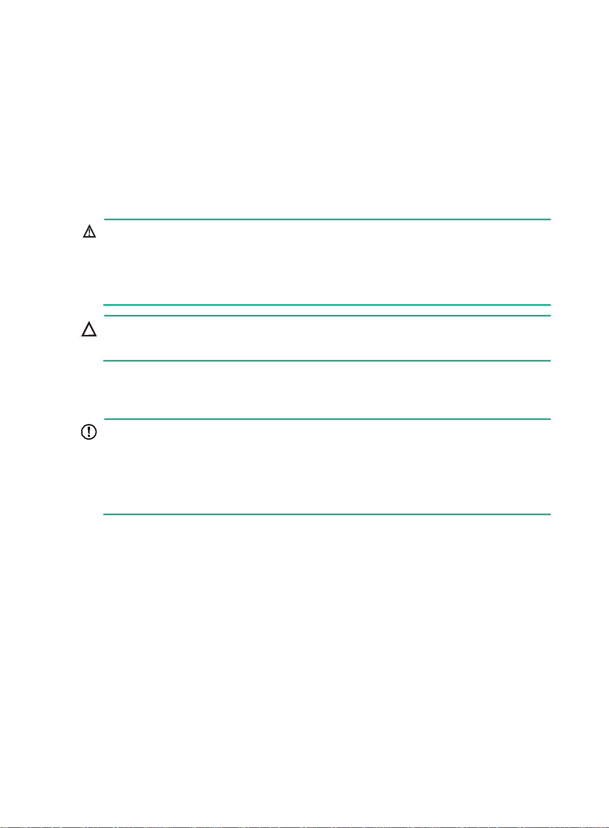
Removing the switch ············································································································3
Connecting the switch to the network ·····························································································4
Precautions························································································································4
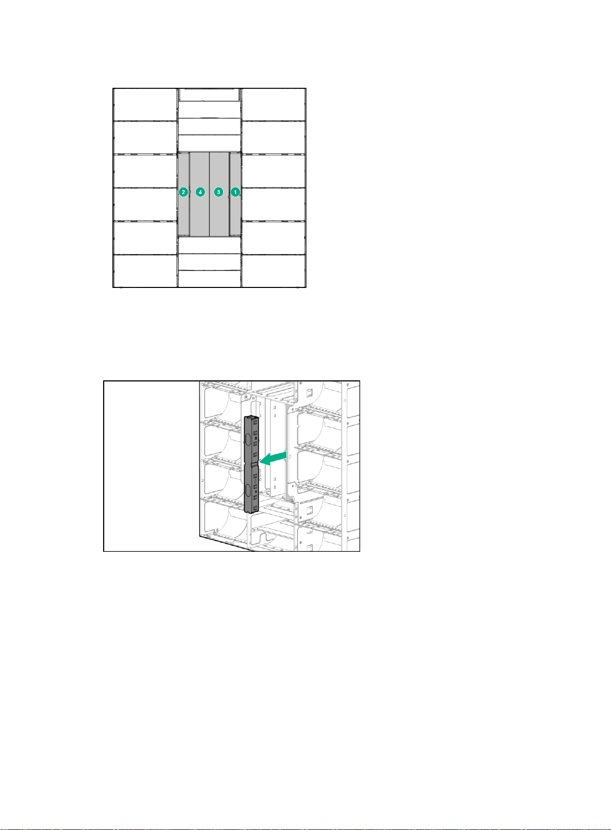
Connecting the optical fibers··································································································4
Accessing the switch for the first time ···················································6
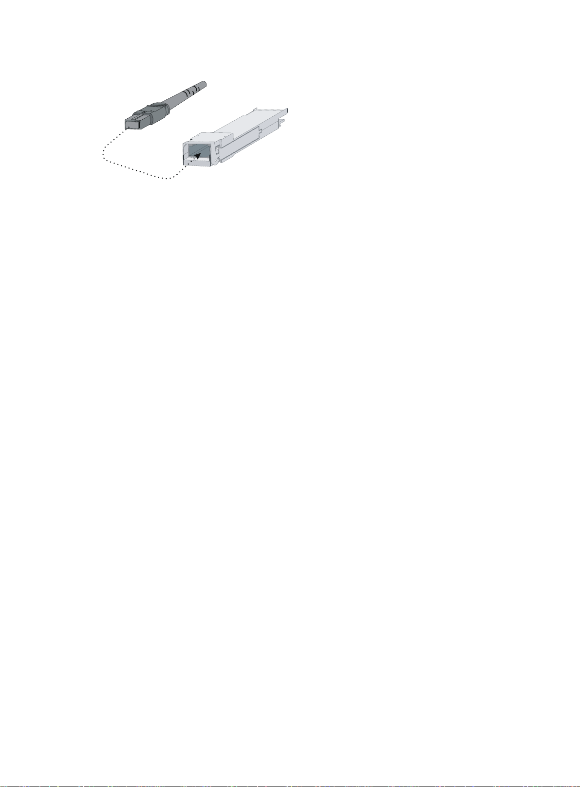
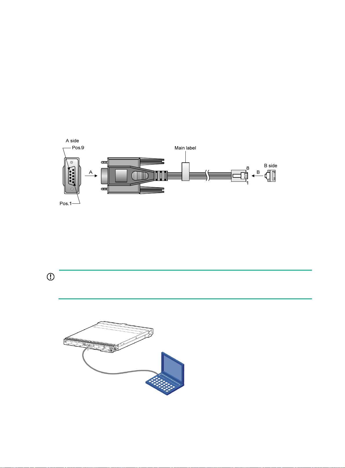
Logging in through the console port ·······························································································6
Setting up the configuration environment ··················································································6
Setting terminal parameters···································································································7
Configuring the switch·················································································································7
Configuring an authentication method······················································································7
Configuring the basic network settings ·····················································································7
Configuration example··········································································································8
Setting up an IRF fabric ·····································································9
Planning IRF fabric setup·············································································································9
Determining the number of IRF member devices········································································9
Identifying the master switch and planning IRF member IDs ·························································9
Planning IRF topology and connections····················································································9
Configuring basic IRF settings ···································································································· 10
Connecting the physical IRF ports ······························································································· 11
Accessing the IRF fabric to verify the configuration ········································································· 11
Troubleshooting ·············································································12
Troubleshooting methods ·········································································································· 12
Collecting log and operating information ······················································································· 12
Collecting common log messages ························································································· 13
Collecting diagnostic log messages······················································································· 13
Collecting operating statistics······························································································· 14
Failures at startup ···················································································································· 15
No display on the configuration terminal ················································································· 15
Garbled display on the configuration terminal ·········································································· 15
Failures during operation ··········································································································· 16
IRF member device failure ········································································································· 16
Software upgrade failure············································································································ 16
Hardware failures····················································································································· 17
Interface failure ······················································································································· 17
Document conventions and icons ······················································19
Conventions ··························································································································· 19
Network topology icons ············································································································· 20
Support and other resources ···························································· 21
Accessing Hewlett Packard Enterprise Support ·············································································· 21
Accessing updates ··················································································································· 21
Websites ························································································································· 22
Customer self repair··········································································································· 22
Remote support ················································································································ 22
Documentation feedback ···································································································· 23
Appendix A Chassis views and technical specifications ·························· 24
Chassis views ························································································································· 24
Port numbering························································································································ 24

ii
Technical specifications············································································································· 25
Appendix B Ports and LEDs ·····························································26
Ports ····································································································································· 26
Console port····················································································································· 26
SFP+ port ························································································································ 26
QSFP+ port······················································································································ 27
LEDs····································································································································· 29
Appendix C Cables········································································· 30
Fiber connector ······················································································································· 30
SFP+ cable····························································································································· 30
QSFP+ cable ·························································································································· 31
QSFP+ to SFP+ cable··············································································································· 31
Index ···························································································32

1
Installing the switch
This manual provides instructions for installing an HPE Apollo Ethernet 10/40GbE Switch in an HPE
Apollo 6000 Gen10 chassis.
For more information about product features, specifications, options, configurations, and
compatibility, see the product QuickSpecs on the Hewlett Packard Enterprise website.
Preparing for installation
WARNING!
•The switch is Class 1 laser device. Do not stare into any open apertures of operating transceive
r
modules or optical fiber connectors. The laser light emitted from these apertures might hurt your
eyes.
•To avoid any equipment damage or bodily injury caused by improper use, strictly follow the safety
recommendations for installation. For more information, see the chassis installation guide.
CAUTION:
Take ESD measures to avoid damaging the components. For more information, see the chassis
installation guide.
Installing and removing the switch
IMPORTANT:
•Do not use excessive force during the installation and removal processes.
•Remove the cables before removing the switch.
•If the switch does not install easily, make sure it is correctly oriented.
•To prevent dust from entering the system, install the filler panel into the interconnect bay after
removing the switch.
Installing the switch
You can install the switch only in bay 1 or bay 2, or both. Bay 1 and bay 2 are located in the rear of the
chassis (see Figure 1). For more information on port mapping and population guidelines, see the
HPE Apollo k6000 Chassis User Guide.

2
Figure 1 Rear of the chassis
To install the switch:
1. Wear an ESD wrist strap and make sure it makes good skin contact and is reliably grounded.
2. Remove the filler panel from bay 1 (see Figure 2). Keep the removed filler panel for future use.
Figure 2 Removing the filler panel
3. Unpack the switch.
4. Fully open the release lever and then pull the release lever to the open position (see callout 1
in Figure 3).

3
Figure 3 Installing the switch in bay 1
5. Slide the switch into bay 1 (see callout 2 in Figure 3) until it touches the backplane.
6. Push the release lever to the closed position (see callout 3 in Figure 3).
7. Verify that the Health LED is green after the switch starts up.
If the Health LED is not green, verify the installation.
8. Choose correct cables to connect to the ports on the switch.
For more information about ports, see "Ports." For more information about cable installation,
see "Connecting the switch to the network."
9. You can follow the same steps to install another switch in bay 2 (see Figure 4).
Figure 4 Installing the switch in bay 2
Removing the switch
1. Wear an ESD wrist strap and make sure it makes good skin contact and is reliably grounded.
2. Press the release tab to open the release lever.
3. Pull the release lever outwards slowly to take out the switch.
4. Install a filler panel in the bay to prevent dust from entering the chassis.

4
Connecting the switch to the network
Precautions
•Make sure the fiber connector and fiber type match the transceiver module type.
•The fiber ports have shielded covers. Remove the shielded covers before using the fiber ports
and keep them safely. Fiber interfaces must be installed with shielded covers when they are not
in use.
•Fiber connectors must be protected under safe and reliable outer packing, and be fitted with
dust caps. Fiber connectors must be installed with dust caps when they are not in use. Take
care not to scratch their end face. Replace the dust cap if it is loose or polluted.
•Before connecting a fiber, use dust free paper and absolute alcohol to clean the end face of the
fiber connector. You can brush the end face only in one direction. You also need to brush the
end face of the fiber port.
•Never bend or curve a fiber when connecting it.
•For the QSFP+ module, you do not need to differentiate between the transmitter (TX) and
receiver (RX) ports. For other types of transceiver modules, the TX port on one end must
connect to the RX port on the other end.
Connecting the optical fibers
WARNING!
To avoid injury to your eyes, do not stare at the optical interfaces and optical fiber connectors when
connecting optical fibers.
You can install a transceiver module in a fiber port on the switch and then plug the fiber connector to
the transceiver module. For more information about installing the transceiver module, see HPE
Transceiver Modules and Network Cables Installation Guide.
To install a transceiver module into the port on the switch and the peer device:
1. Remove the dust cover of the fiber connector, and clean the end of the fiber connector.
2. Remove the dust plug of the transceiver module, plug one end of the optical fiber into the
transceiver module, and plug the other end into the transceiver module in the peer device.
Figure 5 Using LC optical fiber connectors to connect transceiver modules
LC plug
SFP+ module

5
Figure 6 Using MPO optical fiber connectors to connect transceiver modules
3. Verify the port LEDs for correct connection.
For more information about LED status, see "LEDs."
After you connect the switch to the network, use the ping or tracert command to test network
connectivity. For more information about these two commands, see HPE Apollo Ethernet 10/40GbE
Switch Series Network Management and Monitoring Command Reference.
MPO plug
QSFP+ module

6
Accessing the switch for the first time
Logging in through the console port
When you access the switch through the console port, you must use a console cable (see Figure 7)
to connect a console terminal, for example, a PC, to the console port on the switch.
A console cable is an 8-core shielded cable, with a crimped RJ-45 connector at one end for
connecting to the console port of the switch, and a DB-9 female connector at the other end for
connecting to the serial port on the console terminal.
Figure 7 Console cable
Setting up the configuration environment
To connect a terminal, for example, a PC, to the switch:
1. Plug the DB-9 female connector of the console cable in the serial port of the PC.
2. Plug the RJ-45 connector of the console cable in the console port of the switch.
IMPORTANT:
•Identify the mark on the console port and make sure you are connecting to the correct port.
•Make sure a DB-9 female connector is available on the terminal. If not, prepare a converter.
Figure 8 Connecting a console port to a terminal

7
Setting terminal parameters
To configure and manage the switch through the console port, you must run a terminal emulator
program, HyperTerminal or PuTTY, on your configuration terminal. You can use the emulator
program to connect a network device, a Telnet site, or an SSH site. For more information about the
terminal emulator programs, see the user guides for these programs.
The following are the required terminal settings:
•Bits per second—115200.
•Data bits—8.
•Parity—None.
•Stop bits—1.
•Flow control—None.
Configuring the switch
By default, the switch does not authenticate console login users. To increase system security and
enable remote management:
•Configure a login authentication method, for example, Telnet, SSH, or NMS.
•Configure access services.
Configuring an authentication method
You can configure authentication on a user interface to control access to the switch.
Table 1 describes the Telnet login authentication methods available for a VTY user interface. For
more information about login authentication methods, see HPE Apollo Ethernet 10/40GbE Switch
Series Fundamentals Configuration Guide.
Table 1 Telnet login authentication methods
Authentication
method Characteristics Application scenarios
None Easy to configure, insecure Lab environments and extremely secure
network environments
Password Easy to configure, secure, providing flat
user management
Environments that do not need granular
privilege management
Username and
password
Complex to configure, secure, providing
hierarchical user management
Environments where multiple operators
cooperate to manage the switch
Configuring the basic network settings
An HPE Apollo Ethernet 10/40GbE Switch without any configuration will continuously attempt to
obtain an IP address via DHCP. After obtaining an IP address, it downloads a configuration file based
on DHCP options 67 and 150. To use the auto-configuration feature, see HPE Apollo Ethernet
10/40GbE Switch Series Fundamentals Configuration Guide.
The switch can perform basic data forwarding immediately after connecting to a network. To
implement more forwarding features, configure the basic network settings such as IP address, static
route, and VLAN. For more information, see HPE Apollo Ethernet 10/40GbE Switch Series
Configuration Guides.

8
Configuration example
Configuring Telnet
# Enter system view.
<Sysname> system-view
# Enable the Telnet server.
[Sysname] telnet server enable
# Enter the user interface view VTY 0. The device supports 16 concurrent VTY users.
[Sysname] user-interface vty 0
# Enable password authentication on the user interface.
[Sysname-ui-vty0] authentication-mode password
# Set the password to hello.
[Sysname-ui-vty0] set authentication password simple hello
# Set the user role to network-admin so Telnet users accessing VTY 0 can use all commands.
[Sysname-ui-vty0] user-role network-admin
[Sysname-ui-vty0] quit
Configuring the basic network settings
1. Specify an IP address:
# Create VLAN-interface 1.
[Sysname] interface vlan-interface 1
# Assign an IP address, for example, 192.168.0.1, to VLAN-interface 1.
[Sysname-Vlan-interface1] ip address 192.168.0.1 24
[Sysname-Vlan-interface1] quit
2. Configure a static route:
# Configure a static route, with the destination IP address 172.16.1.0 and the next hop IP
address 192.168.0.2.
[Sysname] ip route-static 172.16.1.0 255.255.255.0 192.168.0.2
3. Configure a VLAN:
# Create VLAN 10 and enter its view.
[Sysname] vlan 10
[Sysname-vlan10]
# Assign Ten-GigabitEthernet 2/1/6 to VLAN 10.
[Sysname-vlan10] port ten-gigabitethernet 2/1/6
[Sysname-vlan10] quit

9
Setting up an IRF fabric
You can use HPE Intelligent Resilient Framework (IRF) technology to connect and virtualize HPE
Apollo Ethernet 10/40GbE Switches into a virtual switch called an "IRF fabric" or "IRF virtual device"
for flattened network topology, and high availability, scalability, and manageability.
Planning IRF fabric setup
Determining the number of IRF member devices
Choose HPE Apollo Ethernet 10/40GbE Switch and identify the number of required IRF member
switches, depending on the user density and upstream bandwidth requirements. The switching
capacity of an IRF fabric equals the total switching capacities of all member switches.
Identifying the master switch and planning IRF member IDs
IRF member switches will automatically elect a master. You can affect the election result by
assigning a high member priority to the intended master switch. For more information about master
election, see HPE Apollo Ethernet 10/40GbE Switch Series IRF Configuration Guide.
Determine which switch you want to use as the master for managing all member switches in the IRF
fabric. An IRF fabric has only one master switch. You configure and manage all member switches in
the IRF fabric at the command line interface of the master switch.
Prepare an IRF member ID assignment scheme. An IRF fabric uses member IDs to uniquely identify
and manage its members, and you must assign each IRF member switch a unique member ID.
Planning IRF topology and connections
You can create an IRF fabric in daisy chain topology, or more reliably, ring topology. In ring topology,
the failure of one IRF link does not cause the IRF fabric to split as in daisy chain topology. Rather, the
IRF fabric changes to a daisy chain topology without interrupting network services.
You connect the IRF member switches through IRF ports, the logical interfaces for the connections
between IRF member switches. Each IRF member switch has two IRF ports: IRF-port 1 and IRF-port
2. An IRF port goes up when you bind the first member physical port to it.
When connecting IRF member switches, you must connect the physical ports of IRF-port 1 on one
switch to the physical ports of IRF-port 2 on its neighbor switch.
The following physical ports can be used for IRF connections:
•SFP+ ports and QSFP+ ports. For more information about the transceiver modules and cables
available for the SFP+ and QSFP+ ports, see Table 8, Table 9, Table 10, and Tabl e 11 .
•Crosslink ports. A crosslink port is an internal port on a switch that connects to the switch in the
adjacent horizontal interconnect bay in the chassis. The switch has four crosslink ports: Port 49,
Port 50, Port 51, and Port 52. By default, the four ports are shut down to avoid loops. To create
an IRF fabric on two switches by using crosslink ports, execute the undo shutdown command
to bring up the crosslink ports with the same number on the switches.

10
Figure 9 IRF fabric in daisy chain topology
Figure 10 IRF fabric in ring topology
Figure 11 Connecting IRF member switches using crosslink ports
Configuring basic IRF settings
After you install the IRF member switches, power on the switches, and log in to each IRF member
switch (see HPE Apollo Ethernet 10/40GbE Switch Series Fundamentals Configuration Guide) to
configure their member IDs, member priorities, and IRF port bindings.
For more information about configuring basic IRF settings, see HPE Apollo Ethernet 10/40GbE
Switch Series IRF Configuration Guide.

11
Connecting the physical IRF ports
Connect the IRF member switches as planned.
NOTE:
Wear an ESD wrist strap when you connect cables or transceiver modules and fibers. For how to
connect them, see HPE Transceiver Modules and Network Cables Installation Guide.
Accessing the IRF fabric to verify the configuration
To verify the basic functionality of the IRF fabric after you finish configuring basic IRF settings and
connecting IRF ports:
1. Log in to the IRF fabric through the console port of any member switch.
2. Create a Layer 3 interface, assign it an IP address, and make sure the IRF fabric and the
remote network management station can reach each other.
3. Use Telnet, web, or SNMP to access the IRF fabric from the network management station. (See
HPE Apollo Ethernet 10/40GbE Switch Series Fundamentals Configuration Guide.)
4. Verify that you can manage all member switches as if they were one node.
5. Display the running status of the IRF fabric by using the commands in Table 2.
Table 2 Displaying and maintaining IRF configuration and running status
Task Command
Display information about the IRF fabric display irf
Display all members’ configurations display irf configuration
Display topology information about the IRF fabric display irf topology
NOTE:
To avoid IP address collision and network problems, configure a minimum of one multi-active
detection (MAD) mechanism to detect the presence of multiple identical IRF fabrics and handle
collisions. For more information about MAD detection, see HPE Apollo Ethernet 10/40GbE Switch
Series IRF Configuration Guide.

12
Troubleshooting
IMPORTANT:
To prevent configuration loss, save the configuration each time you finish configuring a feature. Fo
r
configuration recovery, regularly back up the configuration to a remote server
Troubleshooting methods
When your switch fails, you can use the following methods to troubleshoot the switch:
•At the CLI, use related commands to display system operating information, and locate the
failures.
•Locate the failures according to the LED status on the switch. For more information, see
"LEDs."
NOTE:
If you cannot locate failures by following the guidelines in this chapter, contact Hewlett Packard
Enterprise Support.
Collecting log and operating information
IMPORTANT:
By default, the information center is enabled. If the feature is disabled, you must use the info-cente
r
enable command to enable the feature for collecting log messages.
Table 3 shows the types of files that the system uses to store operating log and status information.
You can export these files by using FTP or TFTP.
In an IRF system, these files are stored on the master device. Multiple devices will have log files if
master/subordinate switchovers have occurred. You must collect log files from all these devices. To
more easily locate log information, use a consistent rule to categorize and name files. For example,
save log files to a separate folder for each member device, and include their slot numbers in the
folder names.
Table 3 Log and operating information
Category File name format Content
Common log logfile.log Command execution and operational log messages.
Diagnostic log diagfile.log
Diagnostic log messages about device operation, including the
following items:
•Parameter settings used when an error occurs.
•Information about device startup errors.
•Handshaking information between member devices when
a communication error occurs.

13
Category File name format Content
Operating
statistics file-basename.gz
IMPORTANT:
Collecting operating statistics decreases system performances.
Current operation statistics for feature modules, including the
following items:
•Device status.
•CPU status.
•Memory status.
•Configuration status.
•Software entries.
•Hardware entries.
Collecting common log messages
1. Save the common log messages from the log buffer to a log file.
By default, the log file is saved in the logfile directory of the flash memory on each member
device.
<Sysname> logfile save
The contents in the log file buffer have been saved to the file
flash:/logfile/logfile.log
2. Identify the log file on each member device:
# Display the log file on the master device.
<Sysname> dir flash:/logfile/
Directory of flash:/logfile
0 -rw- 21863 Jul 11 2013 16:00:37 logfile.log
524288 KB total (107944 KB free)
# Display the log file on each subordinate device:
<Sysname> dir slot2#flash:/logfile/
Directory of slot2#flash:/logfile
0 -rw- 21863 Jul 11 2013 16:00:37 logfile.log
524288 KB total (107944 KB free)
3. Transfer the files to the desired destination by using FTP or TFTP. (Details not shown.)
Collecting diagnostic log messages
1. Save the diagnostic log messages from the diagnostic log file buffer to a diagnostic log file.
By default, the diagnostic log file is saved in the diagfile directory of the flash memory on each
member device.
<Sysname> diagnostic-logfile save
The contents in the diagnostic log file buffer have been saved to the file
flash:/diagfile/diagfile.log
2. Identify the diagnostic log file on each member device:
# Display the diagnostic log file on the master device.
<Sysname> dir flash:/diagfile/
Directory of flash:/diagfile

14
0 -rw- 161321 Jul 11 2013 16:16:00 diagfile.log
524288 KB total (107944 KB free)
# Display the diagnostic log file on each subordinate device:
<Sysname> dir slot2#flash:/diagfile/
Directory of slot2#flash:/diagfile
0 -rw- 161321 Jul 11 2013 16:16:00 diagfile.log
524288 KB total (107944 KB free)
# Transfer the files to the desired destination by using FTP or TFTP. (Details not shown.)
Collecting operating statistics
You can collect operating statistics by saving the statistics to a file or displaying the statistics on the
screen.
When you collect operating statistics, follow these guidelines:
•Log in to the device through a network port (if any) instead of the console port. Network ports
are faster than the console port.
•Do not execute commands during operating statistics collection.
•As a best practice to ensure information completeness, save the statistics to a file.
To collect operating statistics:
1. Disable pausing between screens of output if you want to display operating statistics on the
screen. Skip this step if you are saving statistics to a file.
<Sysname> screen-length disable
2. Collect operating statistics for multiple feature modules.
<Sysname> display diagnostic-information
Save or display diagnostic information (Y=save, N=display)? [Y/N] :
3. At the prompt, choose to save or display operating statistics:
# To save operating statistics, enter yat the prompt and then specify the destination file path.
Save or display diagnostic information (Y=save, N=display)? [Y/N] :y
Please input the file name(*.tar.gz)[flash:/diag.tar.gz] :flash:/diag.tar.gz
Diagnostic information is outputting to flash:/diag.tar.gz.
Please wait...
Save successfully.
<Sysname> dir flash:/
Directory of flash:
…
6 -rw- 898180 Jun 26 2013 09:23:51 diag.tar.gz
1021808 KB total (259072 KB free)
# To display operating statistics on the monitor terminal, enter nat the prompt.
Save or display diagnostic information (Y=save, N=display)? [Y/N] :n
……

15
Failures at startup
No display on the configuration terminal
Symptom
The configuration terminal does not have display when the switch is powered on.
Solution
To resolve the problem:
1. Verify that the switch is operating correctly.
2. Verify that the console port is connected to the correct serial port on the terminal.
3. Verify that the console cable is in good quality and is operating correctly.
4. If you use a converter to connect the terminal, a laptop, for example, and the console cable,
make sure the driver for the converter is installed.
5. Verify that the configuration terminal and the console port of the switch have the same settings.
The default setting for the console port are as follows:
Baud rate—115200.
Data bits—8.
Parity—None.
Stop bits—1.
Flow control—None.
Emulation—VT100.
If the console port settings change, change the terminal settings accordingly.
6. If the problem persists, contract Hewlett Packard Enterprise Support.
Garbled display on the configuration terminal
Symptom
The configuration terminal displays garbled text when the switch is powered on.
Solution
To resolve the problem:
1. Verify that the configuration terminal and the console port of the switch have the same settings.
The default setting for the console port are as follows:
Baud rate—115200.
Data bits—8.
Parity—None.
Stop bits—1.
Flow control—None.
Emulation—VT100.
If the console port settings change, change the terminal settings accordingly.
2. If the problem persists, contact Hewlett Packard Enterprise Support.

16
Failures during operation
Symptom
A failure occurs when the switch is operating.
Solution
To resolve the problem:
1. Execute related commands at the CLI to display switch operating information and locate the
fault.
2. If a configuration error is found, re-configure the switch, perform configuration rollback, or
restore the factory-default settings.
For example, if an incorrect IP address is configured for an interface, you can use the undo ip
address command in interface view to delete the IP address and configure a new one.
If multiple configuration errors need to be rectified, you can perform configuration rollback to roll
back the switch to the specified configuration status without rebooting the switch. For more
information about configuration rollback, see HPE Apollo Ethernet 10/40GbE Switch Series
Configuration Guides and HPE Apollo Ethernet 10/40GbE Switch Series Command
References.
3. If the problem persists, contact Hewlett Packard Enterprise Support.
IRF member device failure
Symptom
An IRF member device fails and needs to be replaced.
Solution
To resolve the problem:
1. Prepare a device that is the same model as the failed one.
2. View the startup configuration file saved on an IRF member device that is operating correctly.
Record the IRF member ID of the failed device and how the IRF physical interfaces on the failed
device are bound to the IRF ports.
3. Record the cable connection positions on the failed device and remove all cables from the
failed device.
4. Install the new device in the chassis. The device powers on automatically.
5. Log in to the new device. Configure IRF member ID and IRF port bindings on the new device
based on the recorded IRF configuration information of the failed device.
6. Install the modules and cables for the new device.
7. Activate the IRF port configuration on the new device. The device reboots automatically and
joins the IRF.
8. If the problem persists, contact Hewlett Packard Enterprise Support.
Software upgrade failure
Symptom
Software upgrade fails.
This manual suits for next models
2
Table of contents
Other Helwett Packard Switch manuals
Popular Switch manuals by other brands

Monacor
Monacor HDMS-208 operating instructions

NETGEAR
NETGEAR GS748T - ProSafe Smart Switch installation guide

Cooper
Cooper Aspire instruction manual

Extron electronics
Extron electronics PVS 405D installation guide

HP
HP 2920 Series Quick setup guide

Moxa Technologies
Moxa Technologies EDS-405A Hardware installation guide